warning light LAND ROVER FREELANDER 2001 Workshop Manual
[x] Cancel search | Manufacturer: LAND ROVER, Model Year: 2001, Model line: FREELANDER, Model: LAND ROVER FREELANDER 2001Pages: 1007, PDF Size: 23.47 MB
Page 14 of 1007

CONTENTS
CONTENTS 11
REAR SUSPENSION ................................................................................ 64-1
REPAIRS
Bush - trailing link............................................................................................................................ 64-1
Bearing - hub ................................................................................................................................. 64-2
Damper .......................................................................................................................................... 64-5
Trailing arm .................................................................................................................................... 64-8
Bush - trailing arm .......................................................................................................................... 64-9
Link - adjustable - transverse ......................................................................................................... 64-10
Link - transverse fixed .................................................................................................................... 64-11
Bush - link - transverse .................................................................................................................. 64-12
Sub frame ...................................................................................................................................... 64-13
BRAKES ................................................................................................... 70-1
ADJUSTMENTS
Brake bleed ..................................................................................................................................... 70-1
Cable - handbrake - check and adjust ............................................................................................ 70-2
REPAIRS
Drum - rear ...................................................................................................................................... 70-3
Disc - front....................................................................................................................................... 70-5
Hose - front - primary - LH .............................................................................................................. 70-6
Hose - rear ...................................................................................................................................... 70-7
Cylinder - master - tandem - LHD ................................................................................................... 70-8
Cylinder - master - tandem - RHD................................................................................................... 70-9
Lever assembly - handbrake........................................................................................................... 70-10
Cable - handbrake ......................................................................................................................... 70-11
Switch - handbrake warning ............................................................................................................ 70-12
Switch - stop light ............................................................................................................................ 70-13
Sensor - brake pedal position ........................................................................................................ 70-13
Shoes/pads - front - set................................................................................................................... 70-14
Brake Shoes - rear set .................................................................................................................... 70-15
Servo assembly - LHD .................................................................................................................... 70-17
Servo assembly - RHD ................................................................................................................... 70-19
Vacuum pump - Td4 - manual ........................................................................................................ 70-20
Vacuum pump - Td4 - automatic ..................................................................................................... 70-21
Vacuum - enhancer - KV6 .............................................................................................................. 70-22
Carrier assembly - calliper - front ................................................................................................... 70-23
Wheel cylinder - rear ....................................................................................................................... 70-24
Switch - low fluid level ..................................................................................................................... 70-25
Sensor & harness - front wheel - RH .............................................................................................. 70-25
Sensor & harness - front wheel - LH ............................................................................................... 70-27
Sensor & harness - rear wheel ....................................................................................................... 70-29
Modulator unit ................................................................................................................................. 70-30
Switch - hill descent - from 04MY ................................................................................................... 70-31
Switch - hill descent - up to 03MY................................................................................................... 70-32
Page 23 of 1007

CONTENTS
20 CONTENTS
LIGHTING.................................................................................................. 86-2-1
ADJUSTMENTS
Headlamps - pair - align beam - up to 04MY .................................................................................. 86-2-1
Headlamps - pair - align beam - from 04MY ................................................................................... 86-2-1
REPAIRS
Headlamp assembly - up to 04MY.................................................................................................. 86-2-3
Headlamp assembly - from 04MY .................................................................................................. 86-2-4
Lamp assembly - flasher side repeater - front ................................................................................ 86-2-5
Lamp assembly - tail ....................................................................................................................... 86-2-5
Lamp assembly - number plate ...................................................................................................... 86-2-6
Lamp assembly - fog/driving - from 04MY ...................................................................................... 86-2-6
Lamp assembly - rear ..................................................................................................................... 86-2-7
Lamp assembly - centre high mounted stop (CHMSL) ................................................................... 86-2-7
Lamp assembly - glove compartment ............................................................................................. 86-2-8
Lamp assembly - load space .......................................................................................................... 86-2-8
Switch - headlamp levelling ............................................................................................................ 86-2-9
Switch - glove compartment ........................................................................................................... 86-2-9
Switch - hazard warning ................................................................................................................. 86-2-10
Switch - combined direction indicator/headlight/horn ..................................................................... 86-2-10
Switch - rear fog lamp ..................................................................................................................... 86-2-11
CONTROL UNITS ..................................................................................... 86-3-1
REPAIRS
Control unit - window lift ................................................................................................................. 86-3-1
Relay - power folding mirrors - from 02MY ..................................................................................... 86-3-1
Central Control Unit (CCU) ............................................................................................................. 86-3-2
Control Unit - power fold mirrors - up to 02MY ............................................................................... 86-3-3
SECURITY................................................................................................. 86-4-1
REPAIRS
Solenoid/motor - taildoor................................................................................................................. 86-4-1
Switch/push - horn .......................................................................................................................... 86-4-2
Horn ................................................................................................................................................ 86-4-2
Immobilisation - electronic control unit (ECU) - ............................................................................. 86-4-3
Sensor - volumetric - alarm system - 3 door ................................................................................... 86-4-3
Module (ECU) - volumetric - alarm system - 5 door - without sunroof ........................................... 86-4-5
Module (ECU) - volumetric - alarm system - 5 door - with sunroof ................................................ 86-4-7
Receiver - alarm system ................................................................................................................. 86-4-10
Coil - passive immobilisation - alarm system .................................................................................. 86-4-10
Page 24 of 1007

CONTENTS
CONTENTS 21
WINDOWS ................................................................................................ 86-5-1
REPAIRS
Motor & control unit - front door - 3 door ......................................................................................... 86-5-1
Motor & control unit - front door - 5 door ......................................................................................... 86-5-2
Switch - master window - 5 door - from 04MY ................................................................................ 86-5-2
Relay - control - tail door glass ....................................................................................................... 86-5-3
Microswitch - hardtop sensing - 3 door ........................................................................................... 86-5-4
Relay - heated front screen ........................................................................................................... 86-5-5
Switch - backlight heater ................................................................................................................. 86-5-6
IN CAR ENTERTAINMENT ...................................................................... 86-6-1
REPAIRS
Radio - up to 04MY ......................................................................................................................... 86-6-1
Radio/CD - from 04MY .................................................................................................................... 86-6-2
Speaker - rear - 3 door .................................................................................................................... 86-6-3
Speaker - rear - 5 door .................................................................................................................... 86-6-3
Speaker - front ................................................................................................................................ 86-6-4
Aerial - manual - 3 door .................................................................................................................. 86-6-4
Aerial - manual - 5 door .................................................................................................................. 86-6-5
Coaxial lead - front aerial - 3 door ................................................................................................... 86-6-6
Coaxial lead - front aerial - 5 door ................................................................................................... 86-6-7
Speaker - tweeter - front ................................................................................................................. 86-6-8
Speaker - tweeter - rear - 3 door ..................................................................................................... 86-6-9
Amplifier - power ............................................................................................................................ 86-6-10
Sub-woofer assembly .................................................................................................................... 86-6-11
Coaxial lead - extension.................................................................................................................. 86-6-12
HARNESSES ............................................................................................ 86-7-1
REPAIRS
Fuse box - passenger compartment ............................................................................................... 86-7-1
Harness - main ................................................................................................................................ 86-7-2
Harness - tailgate ............................................................................................................................ 86-7-12
Harness - interior lights - 5 door ...................................................................................................... 86-7-15
Harness - front door - 5 door ........................................................................................................... 86-7-15
Harness - rear door ......................................................................................................................... 86-7-16
DRIVER CONTROLS ................................................................................ 86-8-1
REPAIRS
Switch - remote control - audio system .......................................................................................... 86-8-1
Switch - park distance control (PDC) - from 04 MY ........................................................................ 86-8-1
Control unit (ECU) - parking aid - from 04MY ................................................................................. 86-8-2
Sensor - parking aid - rear - from 04MY ......................................................................................... 86-8-2
Sounder - parking aid - rear - from 04MY ....................................................................................... 86-8-3
Switch - handbrake warning ............................................................................................................ 86-8-3
Switch - hazard warning - from 04MY ............................................................................................. 86-8-4
Cigar lighter - front .......................................................................................................................... 86-8-4
Switch - control - exterior mirror ...................................................................................................... 86-8-5
Page 48 of 1007
GENERAL INFORMATION
03-17
SPX Corporation,
665, Eisenhower Drive,
Owatonna,
MN 55060,
USA
( 0018 772979110
) 0018 005787375
Australia
SPX Australia,
28, Clayton Road,
Notting Hill,
Victoria 3168,
Australia
( 00 (61) 00395446222
) 00 (61) 0395445222
e-mail: [email protected]
Japan and East Asia
Jatek Ltd.,
5 - 53, Minawacho 2-chome,
Kohoku-ku,
Yokohama,
Kanagawa 223-0051,
Japan
( 0081 455627700
) 0081 455627800
Rolling road testing
General
IMPORTANT: Use a four wheel rolling road for
brake testing if possible.
The front and rear wheels cannot be driven
independently due to the viscous coupling. This
eliminates the need for differential lock by
progressively applying more torque to the rear
wheels if the front wheels start to slip.
DO NOT attempt to drive individual wheels with
vehicle supported on floor jacks or stands.
Four wheel rolling road
Provided that front and rear rollers are rotating at
identical speeds and that normal workshop safety
standards are applied, there is no speed restriction
during testing, except any that may apply to the tyres.
Before testing a vehicle with anti-lock brakes on a
four wheel rolling road, disconnect the ABS
modulator. The ABS function will not work, the ABS
warning light will illuminate. Normal braking will be
available.
Two wheel rolling road
ABS will not function on a two wheel rolling road. The
ABS light will illuminate during testing. Normal
braking will be available.
If brake testing on a two wheel rolling road is
necessary, the following precautions should be
taken:
lpropeller shaft to the rear axle is removed/
disconnected;
lneutral selected in gearbox;
lhill descent control not selected.
When checking brakes, run engine at idle speed to
maintain servo vacuum.
Page 49 of 1007
GENERAL INFORMATION
03-18
Fuel handling precautions
Fuel vapour is highly inflammable and in confined
spaces is also explosive and toxic. The vapour is
heavier than air and will always fall to the lowest
level. The vapour can easily be distributed
throughout a workshop by air currents;
consequently, even a small spillage of fuel is
potentially very dangerous.
The following information provides basic precautions
which must be observed if petrol (gasoline) is to be
handled safely. It also outlines other areas of risk
which must not be ignored. This information is issued
for basic guidance only, if in doubt consult your local
Fire Officer.
General
Always have a fire extinguisher containing FOAM,
CO
2, GAS or POWDER close at hand when handling
or draining fuel or when dismantling fuel systems.
Fire extinguishers should also be located in areas
where fuel containers are stored.
Always disconnect the vehicle battery before
carrying out dismantling or draining work on a fuel
system.
Whenever fuel is being handled, drained or stored, or
when fuel systems are being dismantled, all forms of
ignition must be extinguished or removed; any
leadlamps must be flameproof and kept clear of
spillage.
WARNING: No one should be permitted to repair
components associated with fuel without first
having specialist training.
WARNING: Do not remove fuel system
components while the vehicle is over a pit.Fuel tank draining
Fuel tank draining should be carried out in
accordance with the procedure outlined in the FUEL
DELIVERY section of this manual and observing the
following precautions:
WARNING: Fuel must not be extracted or drained
from any vehicle while it is over a pit. Extraction
or draining of fuel must be carried out in a well
ventilated area.
The capacity of containers must be more than
adequate for the amount of fuel to be extracted or
drained. The container should be clearly marked
with its contents and placed in a safe storage
area which meets the requirements of local
authority regulations.
WARNING: When fuel has been drained from a
fuel tank the precautions governing naked lights
and ignition sources should be maintained.
Fuel tank removal
When the fuel line is secured to the fuel tank outlet by
a spring steel clip, the clip must be released before
the fuel line is disconnected or the fuel tank is
removed. This procedure will avoid the possibility of
residual petrol fumes in the fuel tank being ignited
when the clip is released.
As an added precaution, fuel tanks should have a
'FUEL VAPOUR' warning label attached to them as
soon as they are removed from the vehicle.
Fuel tank repairs
No attempt should be made to repair a plastic fuel
tank. If the structure of the tank is damaged, a new
tank must be fitted.
Body repairs
Plastic fuel pipes are particularly susceptible to heat,
even at relatively low temperature, and can be
melted by heat conducted from some distance away.
When body repairs involve the use of heat, all fuel
pipes which run in the vicinity of the repair area must
be removed, and the tank outlet plugged.
Page 151 of 1007
MAINTENANCE
10-4 MAINTENANCE
Seats and Seat Belts
Check
1.Check seat frames are secured to floor and
show no signs of movement.
2.Check operation of seat slide and tilt
mechanisms, ensuring there is no excessive
play between seat cushion and seat back.
3.Check tightness of accessible seat fixings.
4.Fully extract seat belt and allow it to return
under its own recoil mechanism.
5.Check entire length of seat belt webbing for
signs of fraying or damage. Repeat for all belts.
6.Check security of seat belt upper mountings.
7.Check for correct operation of seat belt height
adjusters.
8.Check security of seat belt buckle mountings.
9.Connect each belt to the correct buckle, check
seat belt buckle and tongue are secure.
Release seat belt buckle and check for correct
operation.
10.Check tightness of accessible seat belt
mountings.
Lamps, Horns and Warning Indicators
Check
1.Switch on side, head and tail lights and check
operation.
2.Check headlamp dim/dip operation.
3.Check headlamp levelling operation.
4.Check turn signals and hazard warning lights
operation.
5.Press brake pedal and check operation of
brake lights.
6.Check all exterior lamp lenses for clarity and
condition. Pay particular attention to head lamp
lenses for signs of stone chips or damage.
7.Check horn for loud clear sound.
8.Check operation of all instrument pack warning
and indicator lights.
9.Check for correct operation of interior courtesy
lights.
10.Switch on headlamps (with ignition switch at 'O'
position) and check light reminder warning
operates when door is opened.
Page 169 of 1007
MAINTENANCE
10-22 MAINTENANCE
Engine Oil and Filter – Td4
Drain
1.Raise vehicle on ramp.
2.Remove underbelly panel.
+ EXTERIOR FITTINGS, REPAIRS,
Panel - underbelly.
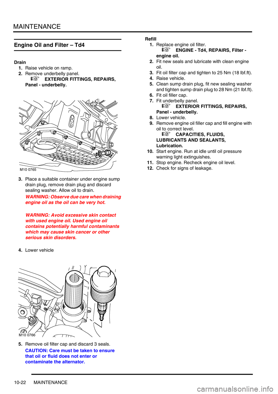
3.Place a suitable container under engine sump
drain plug, remove drain plug and discard
sealing washer. Allow oil to drain.
WARNING: Observe due care when draining
engine oil as the oil can be very hot.
WARNING: Avoid excessive skin contact
with used engine oil. Used engine oil
contains potentially harmful contaminants
which may cause skin cancer or other
serious skin disorders.
4.Lower vehicle
5.Remove oil filter cap and discard 3 seals.
CAUTION: Care must be taken to ensure
that oil or fluid does not enter or
contaminate the alternator.Refill
1.Replace engine oil filter.
+ ENGINE - Td4, REPAIRS, Filter -
engine oil.
2.Fit new seals and lubricate with clean engine
oil.
3.Fit oil filter cap and tighten to 25 Nm (18 lbf.ft).
4.Raise vehicle.
5.Clean sump drain plug, fit new sealing washer
and tighten sump drain plug to 28 Nm (21 lbf.ft).
6.Fit oil filler cap.
7.Fit underbelly panel.
+ EXTERIOR FITTINGS, REPAIRS,
Panel - underbelly.
8.Lower vehicle.
9.Remove engine oil filler cap and fill engine with
oil to correct level.
+ CAPACITIES, FLUIDS,
LUBRICANTS AND SEALANTS,
Lubrication.
10.Start engine. Run at idle until oil pressure
warning light extinguishes.
11.Stop engine. Recheck engine oil level.
12.Check for signs of leakage.
Page 170 of 1007
MAINTENANCE
MAINTENANCE 10-23
Engine Oil and Filter – K1.8
Drain
1.Raise vehicle on ramp.
2.Remove underbelly panel.
+ EXTERIOR FITTINGS, REPAIRS,
Panel - underbelly.
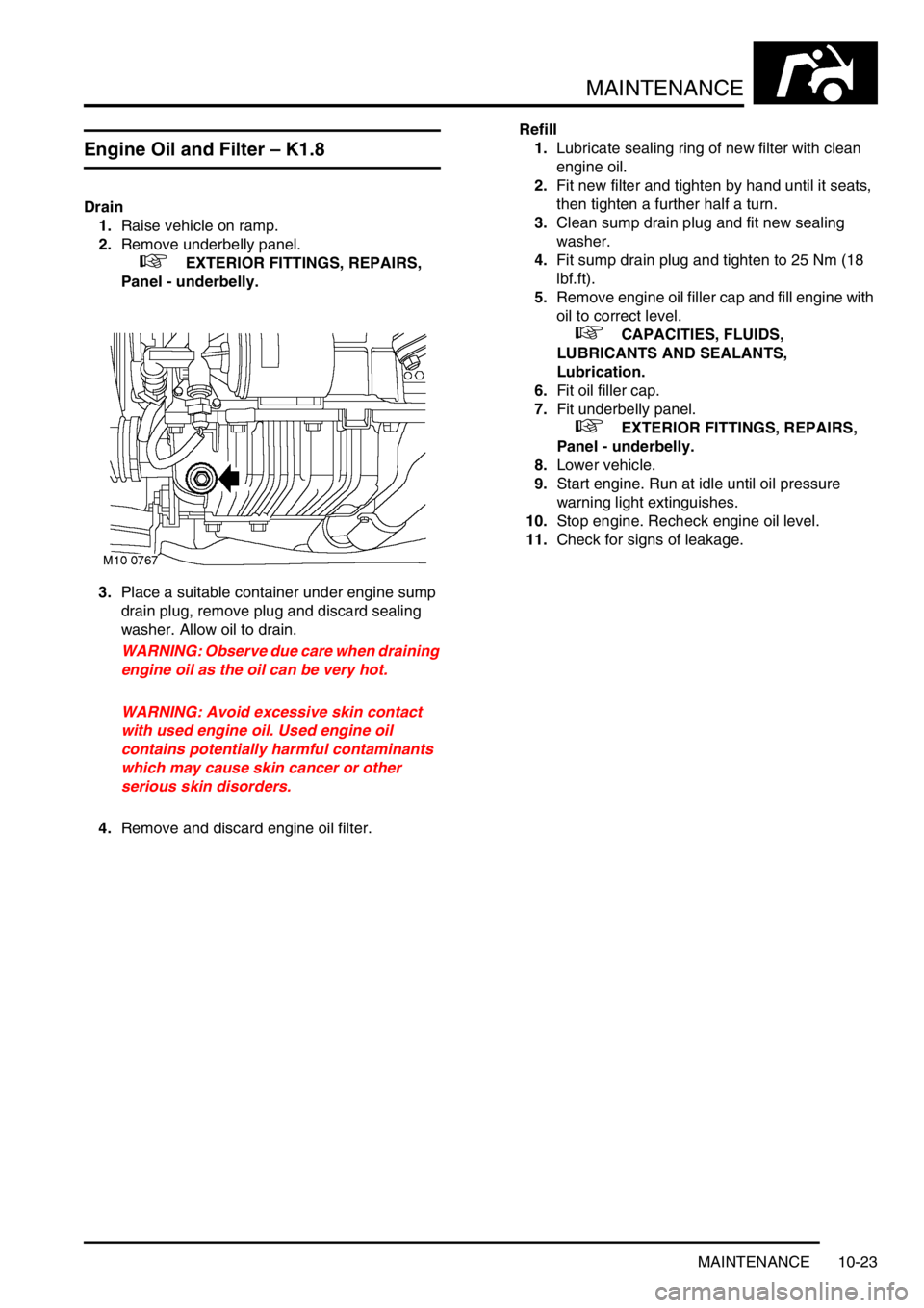
3.Place a suitable container under engine sump
drain plug, remove plug and discard sealing
washer. Allow oil to drain.
WARNING: Observe due care when draining
engine oil as the oil can be very hot.
WARNING: Avoid excessive skin contact
with used engine oil. Used engine oil
contains potentially harmful contaminants
which may cause skin cancer or other
serious skin disorders.
4.Remove and discard engine oil filter.Refill
1.Lubricate sealing ring of new filter with clean
engine oil.
2.Fit new filter and tighten by hand until it seats,
then tighten a further half a turn.
3.Clean sump drain plug and fit new sealing
washer.
4.Fit sump drain plug and tighten to 25 Nm (18
lbf.ft).
5.Remove engine oil filler cap and fill engine with
oil to correct level.
+ CAPACITIES, FLUIDS,
LUBRICANTS AND SEALANTS,
Lubrication.
6.Fit oil filler cap.
7.Fit underbelly panel.
+ EXTERIOR FITTINGS, REPAIRS,
Panel - underbelly.
8.Lower vehicle.
9.Start engine. Run at idle until oil pressure
warning light extinguishes.
10.Stop engine. Recheck engine oil level.
11.Check for signs of leakage.
Page 171 of 1007
MAINTENANCE
10-24 MAINTENANCE
Engine Oil and Filter – KV6
Drain
1.Raise vehicle on ramp.
2.Remove underbelly panel.
+ EXTERIOR FITTINGS, REPAIRS,
Panel - underbelly.
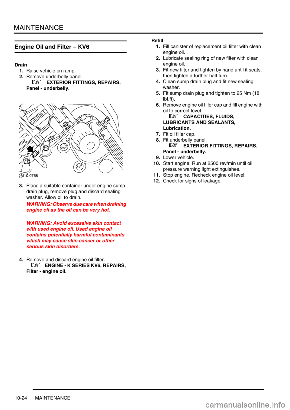
3.Place a suitable container under engine sump
drain plug, remove plug and discard sealing
washer. Allow oil to drain.
WARNING: Observe due care when draining
engine oil as the oil can be very hot.
WARNING: Avoid excessive skin contact
with used engine oil. Used engine oil
contains potentially harmful contaminants
which may cause skin cancer or other
serious skin disorders.
4.Remove and discard engine oil filter.
+ ENGINE - K SERIES KV6, REPAIRS,
Filter - engine oil.Refill
1.Fill canister of replacement oil filter with clean
engine oil.
2.Lubricate sealing ring of new filter with clean
engine oil.
3.Fit new filter and tighten by hand until it seats,
then tighten a further half turn.
4.Clean sump drain plug and fit new sealing
washer.
5.Fit sump drain plug and tighten to 25 Nm (18
lbf.ft).
6.Remove engine oil filler cap and fill engine with
oil to correct level.
+ CAPACITIES, FLUIDS,
LUBRICANTS AND SEALANTS,
Lubrication.
7.Fit oil filler cap.
8.Fit underbelly panel.
+ EXTERIOR FITTINGS, REPAIRS,
Panel - underbelly.
9.Lower vehicle.
10.Start engine. Run at 2500 rev/min until oil
pressure warning light extinguishes.
11.Stop engine. Recheck engine oil level.
12.Check for signs of leakage.
Page 551 of 1007
BRAKES
70-2 ADJUSTMENTS
Cable - handbrake - check and adjust
$% 70.35.10
Check
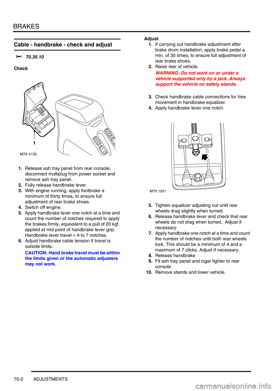
1.Release ash tray panel from rear console,
disconnect multiplug from power socket and
remove ash tray panel.
2.Fully release handbrake lever.
3.With engine running, apply footbrake a
minimum of thirty times, to ensure full
adjustment of rear brake shoes.
4.Switch off engine.
5.Apply handbrake lever one notch at a time and
count the number of notches required to apply
the brakes firmly, equivalent to a pull of 20 kgf.
applied at mid point of handbrake lever grip.
Handbrake lever travel = 4 to 7 notches.
6.Adjust handbrake cable tension if travel is
outside limits.
CAUTION: Hand brake travel must be within
the limits given or the automatic adjusters
may not work.Adjust
1.If carrying out handbrake adjustment after
brake drum installation, apply brake pedal a
min. of 30 times, to ensure full adjustment of
rear brake shoes.
2.Raise rear of vehicle.
WARNING: Do not work on or under a
vehicle supported only by a jack. Always
support the vehicle on safety stands.
3.Check handbrake cable connections for free
movement in handbrake equalizer.
4.Apply handbrake lever one notch.
5.Tighten equalizer adjusting nut until rear
wheels drag slightly when turned.
6.Release handbrake lever and check that rear
wheels do not drag when turned. Adjust if
necessary.
7.Apply handbrake one notch at a time and count
the number of notches until both rear wheels
lock. This should be a minimum of 4 and a
maximum of 7 clicks. Adjust if necessary.
8.Release handbrake
9.Fit ash tray panel and cigar lighter to rear
console.
10.Remove stands and lower vehicle.