ECU LAND ROVER FRELANDER 2 2006 Manual PDF
[x] Cancel search | Manufacturer: LAND ROVER, Model Year: 2006, Model line: FRELANDER 2, Model: LAND ROVER FRELANDER 2 2006Pages: 3229, PDF Size: 78.5 MB
Page 423 of 3229
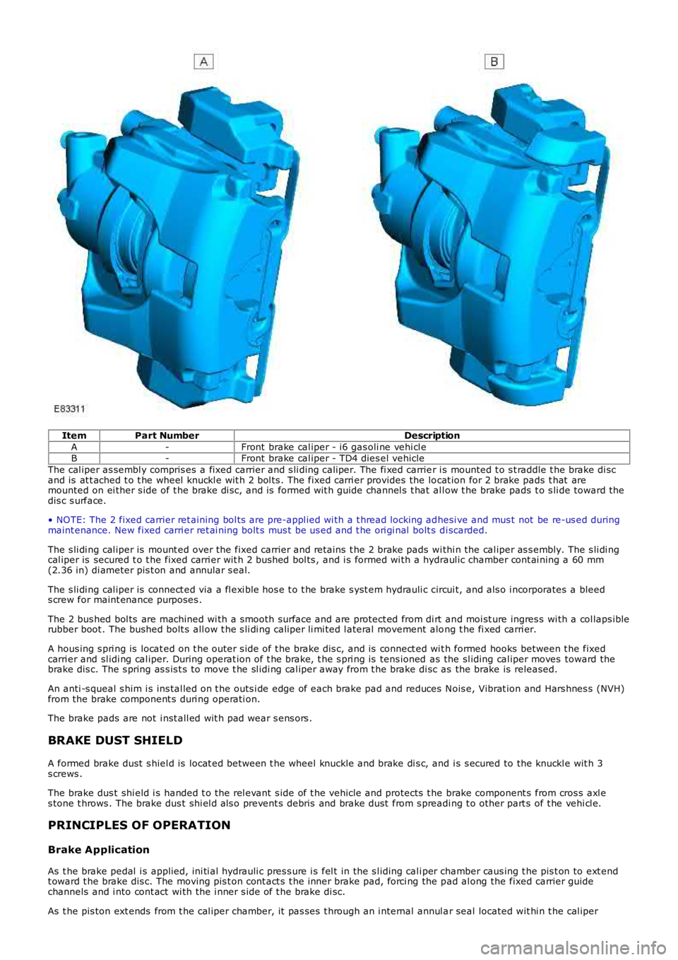
ItemPart NumberDescription
A-Front brake cal iper - i6 gas oli ne vehi cl eB-Front brake cal iper - TD4 dies el vehicle
The cal iper as sembl y compris es a fixed carrier and s li ding caliper. The fi xed carrier i s mounted t o s t raddle t he brake di scand is at t ached t o t he wheel knuckl e wit h 2 bol ts . The fixed carri er provides the locat ion for 2 brake pads t hat aremounted on ei ther s ide of t he brake di sc, and is formed wit h guide channel s t hat al low t he brake pads t o s li de toward t hedis c s urface.
• NOTE: The 2 fixed carrier ret aining bol ts are pre-appl ied wi th a t hread locking adhesi ve and mus t not be re-us ed duringmaint enance. New fixed carri er ret ai ning bolt s mus t be us ed and t he ori gi nal bolt s di scarded.
The s li di ng cal iper is mount ed over the fixed carrier and ret ains t he 2 brake pads wi thi n the cal iper as s embly. The s li di ngcal iper is secured t o t he fixed carri er wit h 2 bus hed bol ts , and i s formed wi th a hydraul ic chamber cont ai ning a 60 mm(2.36 in) di ameter pis t on and annular s eal.
The s li di ng cal iper is connect ed via a fl exi ble hos e t o t he brake s yst em hydrauli c circui t, and als o i ncorporates a bleeds crew for maint enance purposes .
The 2 bus hed bol ts are machined wi th a s mooth surface and are protect ed from di rt and moi st ure ingres s wi th a col laps iblerubber boot . The bushed bolt s all ow t he s li di ng caliper li mi ted l ateral movement along t he fi xed carri er.
A hous ing s pri ng is locat ed on t he outer s ide of t he brake dis c, and is connect ed wit h formed hooks between t he fixedcarri er and sl idi ng cal iper. During operat ion of t he brake, t he s pri ng is tens ioned as the sl iding cal iper moves toward thebrake dis c. The s pring as s is t s to move t he sl idi ng cal iper away from t he brake di sc as the brake is released.
An anti -s queal s him i s ins tal led on t he outs i de edge of each brake pad and reduces Nois e, Vibrat ion and Hars hnes s (NVH)from the brake component s duri ng operati on.
The brake pads are not i nst all ed wit h pad wear s ens ors .
BRAKE DUST SHIELD
A formed brake dust s hiel d is locat ed between t he wheel knuckle and brake di s c, and i s s ecured to the knuckl e wit h 3s crews .
The brake dus t shi eld i s handed t o t he rel evant s ide of t he vehicle and protects t he brake component s from cros s axl es tone t hrows . The brake dus t shi el d als o prevent s debris and brake dust from s preading t o other part s of t he vehi cl e.
PRINCIPLES OF OPERATION
Brake Application
As t he brake pedal i s applied, ini ti al hydrauli c pres s ure i s fel t in the s l iding cali per chamber caus ing t he pis t on to ext endt oward t he brake dis c. The moving pis t on cont act s t he inner brake pad, forci ng the pad al ong the fixed carrier guidechannels and i nto cont act wi th the i nner s ide of t he brake di sc.
As t he pis ton ext ends from t he cal iper chamber, it pas ses t hrough an i nternal annul ar seal located wit hi n t he cal iper
Page 435 of 3229
5
-Dus t s hi eld retai ni ng s crew (4 off)
6 -Brake di sc – s olid (TD4 di esel vehi cle)
7 -Brake di sc ret ai ning s crew
8 -Brake di sc – vent il ated (i6 gas oli ne vehi cl e)
9 -Fixed carrier
10 -Bus hed bol t rubber boot (2 off)
11 -Bus hed bol t
12 -Cali per pi st on s eal
13 -Brake pad retai ni ng s pri ng (2 off)
14 -Out er ant i-squeal shi m
15 -Cali per pi st on
16 -Out er brake pad
17 -Inner brake pad
18 -Sli ding cali per
19 -Inner anti -s queal s him
20 -Cali per bl eed screw
21 -Bleed s crew cap
22 -Bus hed bol t ret aining s crew (2 off)
23 -Rear Left-Hand (LH) wheel knuckle
24 -Fixed carrier ret aining bol t (2 off)
25 -Anti -l ock Brake Syst em (ABS) s ens or ret aining s crew
OVERVIEW
The rear brake as s embly feat ures ei ther a convent ional venti lat ed or a s olid type br ake di s c, and cast -iron sl idi ng cal iper
wit h s i ngl e act ing pi s ton.
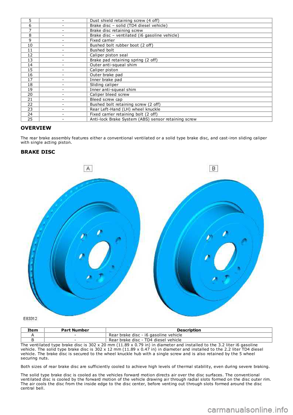
BRAKE DISC Item
Part Number Description
A -Rear brake dis c - i 6 gas ol ine vehicle
B -Rear brake dis c - TD4 di esel vehicle
The vent il ated t ype brake dis c i s 302 x 20 mm (11.89 x 0.79 in) i n diamet er and ins t al led t o t he 3.2 l it er i6 gas oli ne
vehi cl e. The sol id t ype brake dis c i s 302 x 12 mm (11.89 x 0.47 i n) i n diamet er and ins tal led t o t he 2.2 lit er TD4 dies el
vehi cl e. The brake dis c i s s ecured to t he wheel knuckle hub wi th a s ingle screw and is al s o ret ained by t he 5 wheel
s ecuring nuts .
Both si zes of rear brake dis c are suffi ci ent ly cooled to achieve high level s of t her mal st abil it y, even duri ng s evere braking.
The s olid type brake di sc is cooled as t he vehi cles forward moti on direct s air over the di sc surfaces . The convent ional
vent il ated di sc is cooled by t he forward moti on of the vehicle drawing ai r through r adial s lots formed on t he dis c outer rim.
The air cools t he dis c from the i nsi de edge to the di s c cent er, before vent ing out t hrough s lots formed around t he dis c
cent ral bell .
Page 436 of 3229
The brake dis c al so forms t he locati on for t he parking brake component s . The brake d is c i nt ernal diamet er is 185 mm (7.28
in) and i s machined wit h a smoot h s urface to form t he brake drum. An int egral backpl
ate and brake dust s hiel d is mount ed
t o the rear of the brake di s c. The backpl at e enclos es the brake dis c and als o provi d es the mount ing l ocat ion for t he 2
parking brake shoes and operat ing component s.
An apert ure i s formed i n t he dust s hiel d and backplat e t hat al lows t he parking brake cable to protrude t hrough to the i nner
s ide of t he brake dis c, and connect to t he parki ng brake expander uni t. A hol e machi ned i n t he brake dis c outer hub
provides acces s t o t he parking brake manual adjus ter.
For addit ional informat ion, refer t o: Parking Brake (206-05 Parki ng Brake and Act uat ion, Descripti on and Operat ion).
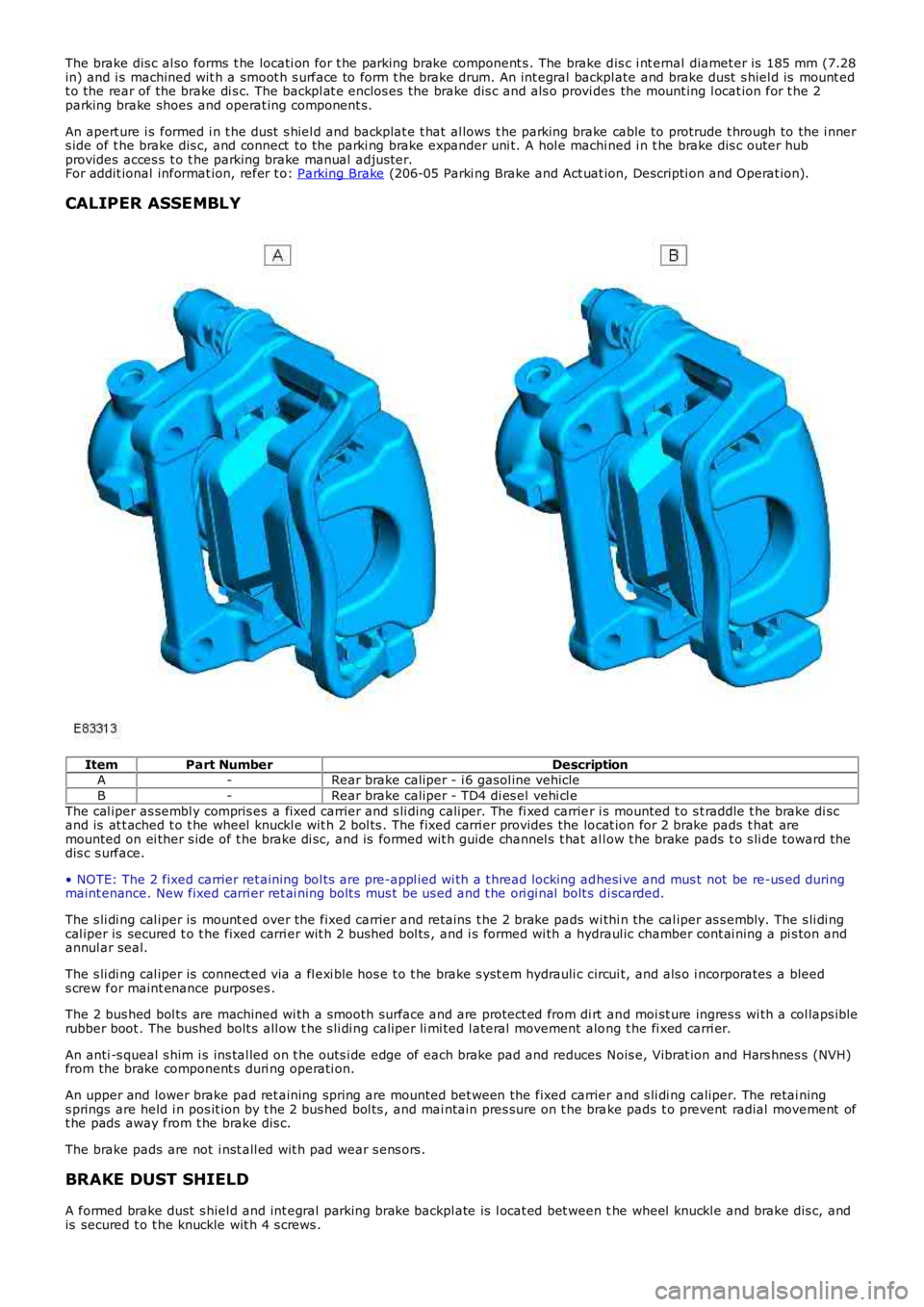
CALIPER ASSEMBLY Item
Part Number Description
A -Rear brake caliper - i 6 gasol ine vehicle
B -Rear brake caliper - TD4 di es el vehi cl e
The cal iper as sembl y compris es a fixed carrier and s li ding caliper. The fi xed carrie r i s mounted t o s t raddle t he brake di sc
and is at t ached t o t he wheel knuckl e wit h 2 bol ts . The fixed carri er provides the lo cat ion for 2 brake pads t hat are
mounted on ei ther s ide of t he brake di sc, and is formed wit h guide channel s t hat al l ow t he brake pads t o s li de toward t he
dis c s urface.
• NOTE: The 2 fixed carrier ret aining bol ts are pre-appl ied wi th a t hread locking ad hesi ve and mus t not be re-us ed during
maint enance. New fixed carri er ret ai ning bolt s mus t be us ed and t he ori gi nal bolt s d i scarded.
The s li di ng cal iper is mount ed over the fixed carrier and ret ains t he 2 brake pads w i thi n the cal iper as s embly. The s li di ng
cal iper is secured t o t he fixed carri er wit h 2 bus hed bol ts , and i s formed wi th a hy draul ic chamber cont ai ning a pi s ton and
annul ar seal.
The s li di ng cal iper is connect ed via a fl exi ble hos e t o t he brake s yst em hydrauli c c ircui t, and als o i ncorporates a bleed
s crew for maint enance purposes .
The 2 bus hed bol ts are machined wi th a s mooth surface and are protect ed from di rt an d moi st ure ingres s wi th a col laps ible
rubber boot . The bushed bolt s all ow t he s li di ng caliper li mi ted l ateral movement alo ng t he fi xed carri er.
An anti -s queal s him i s ins tal led on t he outs i de edge of each brake pad and reduces N ois e, Vibrat ion and Hars hnes s (NVH)
from the brake component s duri ng operati on.
An upper and lower brake pad ret aining spring are mounted bet ween the fixed carrier and s li di ng caliper. The retai ning
s prings are held i n pos it ion by t he 2 bus hed bol ts , and mai ntain pres sure on t he bra ke pads t o prevent radial movement of
t he pads away from t he brake dis c.
The brake pads are not i nst all ed wit h pad wear s ens ors .
BRAKE DUST SHIELD
A formed brake dust s hiel d and int egral parking brake backpl ate is l ocat ed bet ween t he wheel knuckl e and brake dis c, and
is secured t o t he knuckle wit h 4 s crews .
Page 441 of 3229
pad cli p mus t be fit ted i n t he upper pos it ion. Fai lure to foll ow t his
i ns t ructi on may resul t in damage t o t he vehi cl e.
Inst all t he brake pad cli ps .
Inst all t he brake pads.
7.
Secure t he brake caliper.
T orque: 35 Nm 8.
Repeat t he above procedure for t he other s ide.
9.
Inst all t he wheel s and t ires .
Refer t o: W heel and Ti re (204-04 W heel s and Tires, Removal and
Inst all at ion).
10.
Depres s t he brake pedal s everal ti mes , check the fl ui d l evel in the
brake flui d res ervoir and t op-up wi th brake fl uid i f neces s ary.
11.
Page 443 of 3229
Repeat t he above procedure for t he other s ide.
6.
Installation
1. CAUTION: Make s ure that the mati ng faces are cl ean and
free of foreign mat eri al.
Inst all t he brake dis c.
T orque: 35 Nm 1.
2. CAUTIONS: Make s ure that t he mat ing faces are clean and free of foreign
mat eri al . Make s ure that t he brake hos e is not t wis t ed and is correctl y
l ocated.
Secure t he brake caliper and anchor plat e t o t he wheel knuckl e.
T orque: 110 Nm 2.
Repeat t he above procedure for t he other s ide.
3.
Adjus t t he parking brake.
Refer t o: Parking Brake Cabl e Adjus tment (206-05 Parking Brake and
Actuat ion, General Procedures ).
4.
Inst all t he wheel s and t ires .
5.
If neces sary, carry out t he parking brake s hoe bedding-i n procedure.
Refer t o: Parking Brake Shoes Bedding-In (206-05 Parking Brake and
Actuat ion, General Procedures ).
6.
Page 451 of 3229
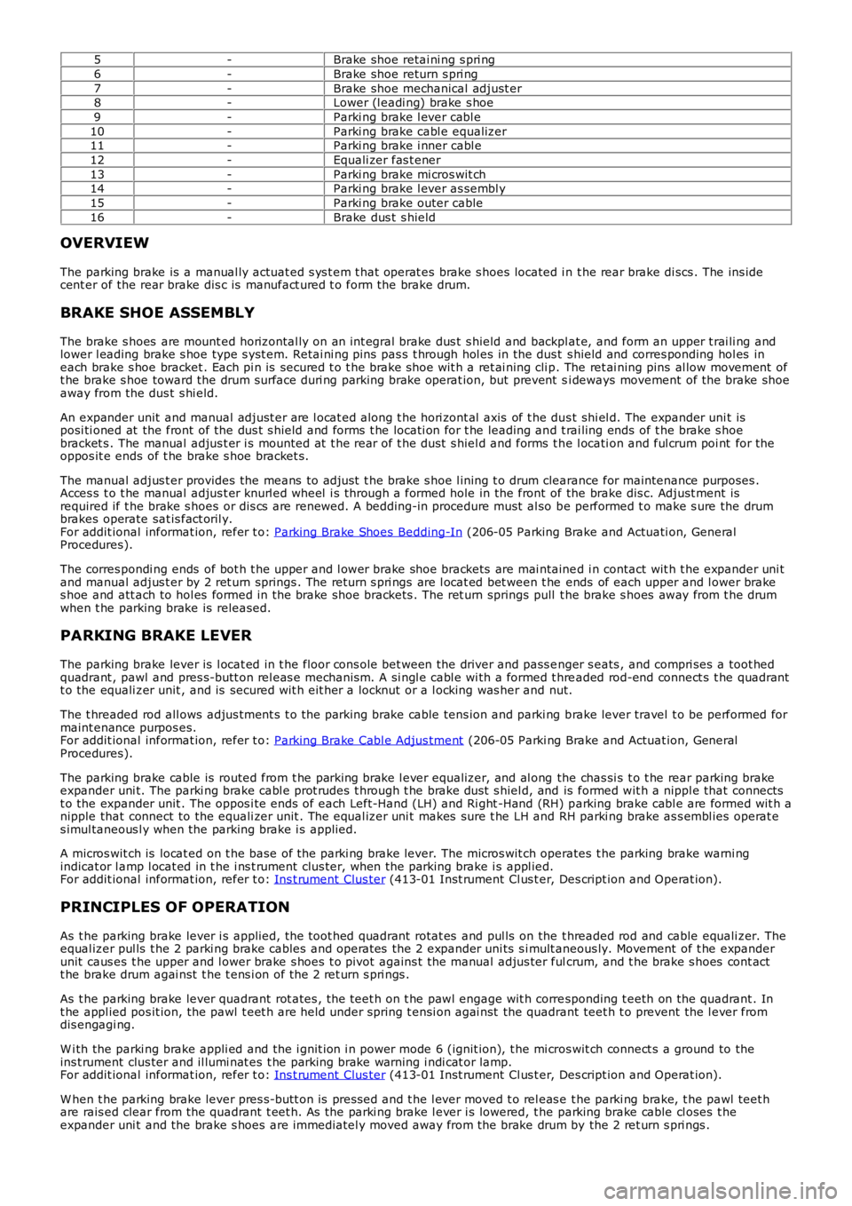
5-Brake shoe retai ni ng s pri ng
6-Brake shoe return s pri ng
7-Brake shoe mechanical adjust er8-Lower (l eadi ng) brake s hoe
9-Parki ng brake l ever cabl e
10-Parki ng brake cabl e equalizer11-Parki ng brake i nner cabl e
12-Equali zer fas t ener
13-Parki ng brake mi cros wit ch14-Parki ng brake l ever as sembl y
15-Parki ng brake outer cable
16-Brake dus t s hield
OVERVIEW
The parking brake is a manual ly actuat ed s ys t em t hat operat es brake s hoes located i n t he rear brake di scs . The ins idecent er of the rear brake dis c is manufact ured t o form the brake drum.
BRAKE SHOE ASSEMBLY
The brake s hoes are mount ed horizontal ly on an int egral brake dus t s hield and backplat e, and form an upper t rai li ng andlower l eading brake s hoe type s yst em. Retai ni ng pins pas s t hrough hol es in the dus t s hield and corres ponding hol es ineach brake s hoe bracket . Each pi n is secured t o t he brake s hoe wit h a ret ai ning cli p. The ret ai ning pins al low movement oft he brake s hoe toward the drum surface duri ng parking brake operat ion, but prevent si deways movement of the brake shoeaway from the dus t s hi eld.
An expander unit and manual adjust er are l ocat ed along t he hori zont al axis of t he dus t shi el d. The expander uni t isposi ti oned at the front of the dus t s hield and forms t he locati on for t he leading and t rai ling ends of t he brake s hoebracket s . The manual adjus t er i s mounted at t he rear of t he dust s hiel d and forms t he l ocati on and ful crum poi nt for theoppos it e ends of t he brake s hoe bracket s.
The manual adjus t er provides the means to adjust t he brake s hoe l ining t o drum clearance for maintenance purposes .Acces s t o t he manual adjus t er knurl ed wheel i s t hrough a formed hole in the front of the brake dis c. Adjust ment isrequired if t he brake s hoes or dis cs are renewed. A bedding-in procedure must al so be performed t o make s ure the drumbrakes operate sat is fact oril y.For addit ional informat ion, refer t o: Parking Brake Shoes Bedding-In (206-05 Parking Brake and Actuati on, GeneralProcedures).
The corres pondi ng ends of bot h t he upper and l ower brake shoe brackets are mai ntained i n contact wit h t he expander uni tand manual adjus t er by 2 ret urn springs . The return s pri ngs are l ocat ed bet ween t he ends of each upper and l ower brakes hoe and att ach to hol es formed in the brake shoe brackets . The ret urn springs pull t he brake s hoes away from t he drumwhen t he parking brake is released.
PARKING BRAKE LEVER
The parking brake lever is l ocat ed in t he floor cons ole bet ween the driver and pass enger s eats , and compri ses a toot hedquadrant , pawl and pres s-butt on rel eas e mechanis m. A si ngl e cabl e wi th a formed t hreaded rod-end connect s t he quadrantt o the equali zer unit , and is secured wit h eit her a locknut or a l ocking was her and nut.
The t hreaded rod all ows adjus tment s t o t he parking brake cable tens ion and parki ng brake lever travel t o be performed formaint enance purpos es.For addit ional informat ion, refer t o: Parking Brake Cabl e Adjus tment (206-05 Parki ng Brake and Actuat ion, GeneralProcedures).
The parking brake cable is routed from t he parking brake l ever equalizer, and al ong the chas si s t o t he rear parking brakeexpander uni t. The parki ng brake cabl e prot rudes t hrough t he brake dust s hiel d, and is formed wit h a nippl e that connectst o the expander unit . The oppos i te ends of each Left-Hand (LH) and Ri ght -Hand (RH) parking brake cabl e are formed wit h anipple that connect to the equali zer unit . The equal izer uni t makes sure t he LH and RH parki ng brake as s embl ies operat es imul taneous l y when the parking brake i s applied.
A micros wit ch is locat ed on t he base of the parki ng brake lever. The micros wit ch operates t he parking brake warni ngindicat or l amp l ocat ed in t he i ns t rument clus ter, when the parki ng brake i s appl ied.For addit ional informat ion, refer t o: Ins t rument Clus ter (413-01 Inst rument Cl us t er, Des cript ion and Operat ion).
PRINCIPLES OF OPERATION
As t he parking brake lever i s applied, t he toot hed quadrant rotat es and pul ls on the t hreaded rod and cable equali zer. Theequal izer pul ls t he 2 parki ng brake cables and operat es the 2 expander uni ts s i mult aneous ly. Movement of t he expanderunit caus es t he upper and l ower brake s hoes t o pivot agains t the manual adjus ter fulcrum, and t he brake s hoes cont actt he brake drum agai nst t he t ens i on of the 2 ret urn s pri ngs .
As t he parking brake lever quadrant rot ates , t he teet h on t he pawl engage wit h corresponding t eeth on the quadrant . Int he appl ied pos it ion, the pawl t eet h are held under spring t ensi on agai nst the quadrant teet h t o prevent the l ever fromdis engagi ng.
W i th the parki ng brake appli ed and the i gnit ion i n power mode 6 (ignit ion), t he mi cros wit ch connect s a ground to theins t rument clus ter and il lumi nat es t he parking brake warning i ndi cat or lamp.For addit ional informat ion, refer t o: Ins t rument Clus ter (413-01 Inst rument Cl us t er, Des cript ion and Operat ion).
W hen t he parking brake lever pres s-butt on is pres sed and t he l ever moved t o rel eas e t he parki ng brake, t he pawl teet hare rais ed clear from the quadrant t eet h. As the parki ng brake l ever i s lowered, t he parking brake cable cl oses t heexpander uni t and the brake s hoes are immediatel y moved away from the brake drum by the 2 ret urn s pri ngs .
Page 486 of 3229
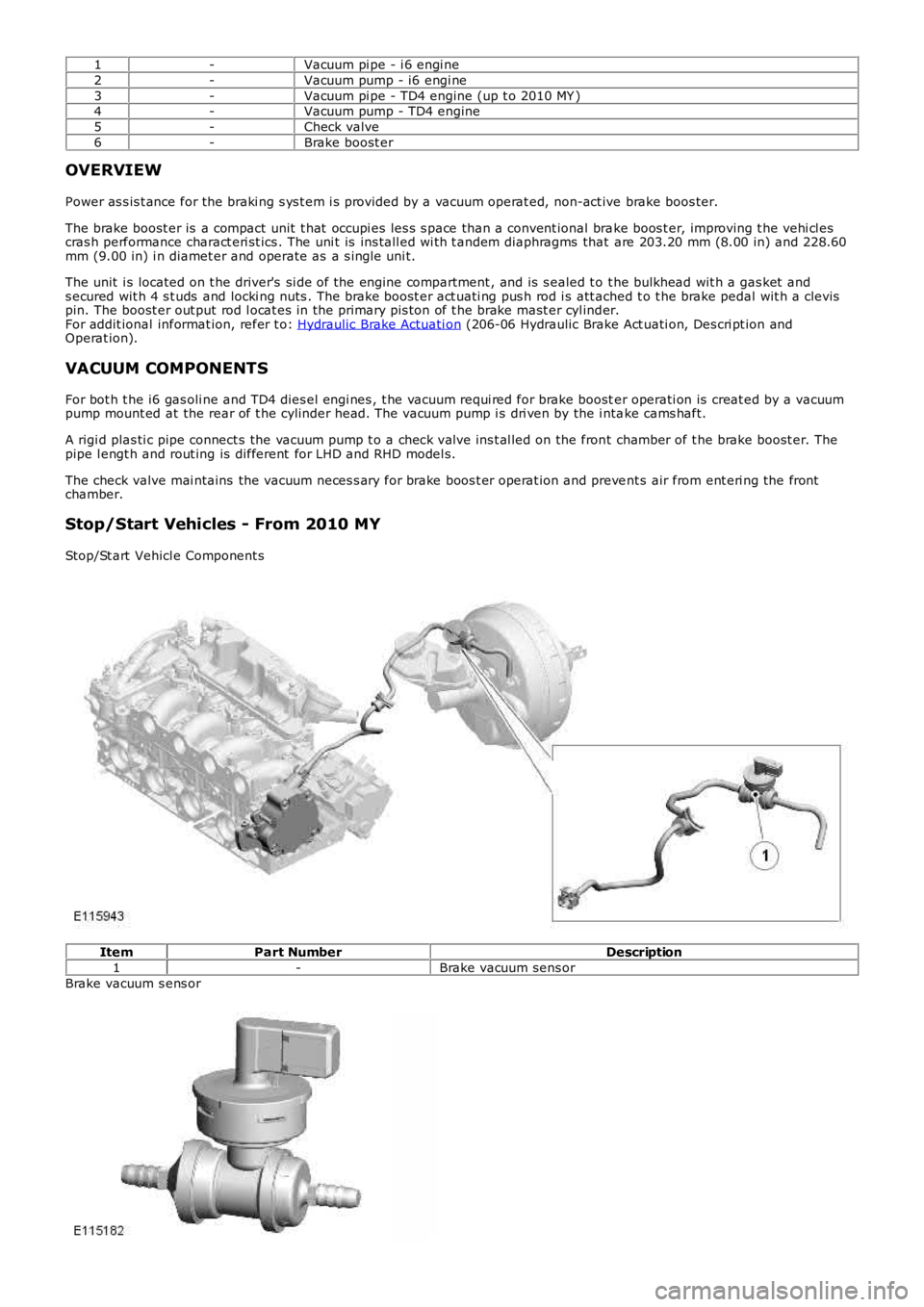
1-Vacuum pi pe - i 6 engi ne
2-Vacuum pump - i6 engi ne
3-Vacuum pi pe - TD4 engine (up t o 2010 MY )4-Vacuum pump - TD4 engine
5-Check valve
6-Brake boost er
OVERVIEW
Power as s is t ance for the braki ng s ys t em i s provided by a vacuum operat ed, non-act ive brake boos ter.
The brake boost er is a compact unit t hat occupi es les s s pace than a convent ional brake boos t er, improving t he vehi cl escras h performance charact eri st ics . The uni t is ins tall ed wi th t andem diaphragms that are 203.20 mm (8.00 in) and 228.60mm (9.00 in) i n diamet er and operate as a s ingle uni t.
The unit i s located on t he driver's si de of the engine compartment , and is s ealed t o t he bulkhead wit h a gas ket ands ecured wit h 4 s t uds and locki ng nuts . The brake boost er act uati ng pus h rod i s att ached t o t he brake pedal wit h a clevispin. The boost er out put rod l ocat es in the primary pis ton of t he brake mast er cyl inder.For addit ional informat ion, refer t o: Hydraulic Brake Actuati on (206-06 Hydraulic Brake Act uati on, Des cri pt ion andOperat ion).
VACUUM COMPONENTS
For bot h t he i6 gas oli ne and TD4 dies el engi nes , t he vacuum requi red for brake booster operati on is creat ed by a vacuumpump mount ed at the rear of t he cylinder head. The vacuum pump i s dri ven by the i ntake cams haft.
A rigi d plas ti c pipe connect s the vacuum pump t o a check valve ins t al led on the front chamber of t he brake boost er. Thepipe l engt h and rout ing is different for LHD and RHD model s.
The check valve mai ntains the vacuum neces s ary for brake boos t er operat ion and prevent s air from ent eri ng the frontchamber.
Stop/Start Vehicles - From 2010 MY
Stop/St art Vehicl e Component s
ItemPart NumberDescription
1-Brake vacuum sens or
Brake vacuum s ens or
Page 504 of 3229
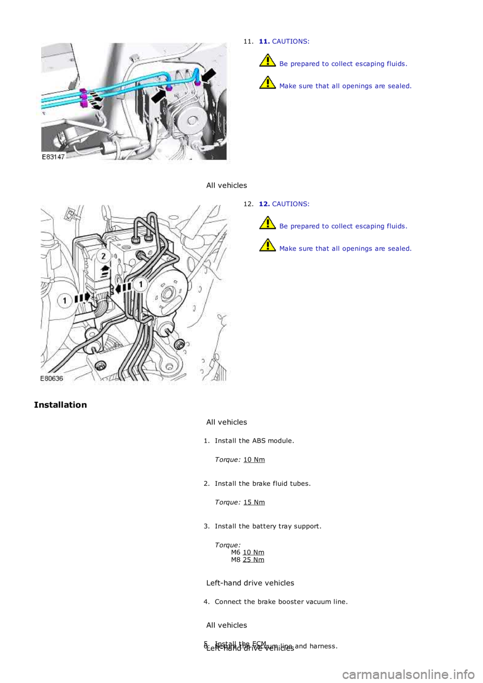
11.
CAUTIONS: Be prepared t o collect es caping flui ds .
Make s ure that all openings are sealed.
11.
All vehicles 12.
CAUTIONS: Be prepared t o collect es caping flui ds .
Make s ure that all openings are sealed.
12.
Installation All vehicles
Inst all t he ABS module.
T orque: 10 Nm 1.
Inst all t he brake fluid tubes.
T orque: 15 Nm 2.
Inst all t he bat t ery t ray s upport .
T orque: M6 10 Nm M8
25 Nm 3.
Left-hand drive vehicles Connect t he brake boost er vacuum l ine.
4.
All vehicles Inst all t he ECM.
5.
Secure t he vacuum line and harnes s .
6.
Left-hand drive vehicles
Page 514 of 3229
For addit ional informat ion, refer t o:
Ins trument Clus ter (413-01 Ins t rument Clus t er, Descripti on and Operat ion),Informat ion and Mes s age Cent er (413-08 Informati on and Mes sage Cent er, Descripti on and Operat ion).
As t he wheel s peed s ens ors are acti ve devi ces , a return s ignal is availabl e when t he road wheels are not rot ati ng. Thisenabl es the ABS modul e t o check t he condi ti on of the s peed s ens ors whil e the vehicl e is st ati onary.
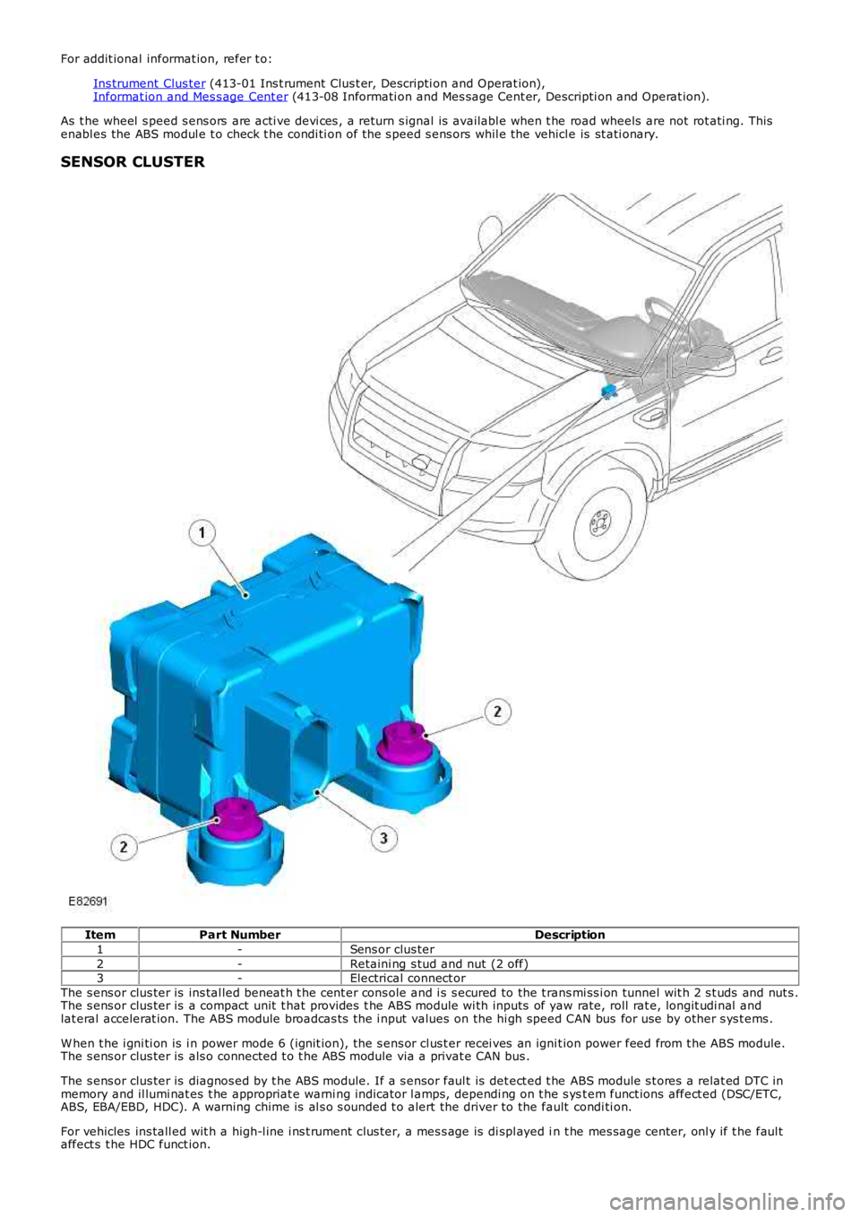
SENSOR CLUSTER
ItemPart NumberDescription
1-Sens or clus ter
2-Retaini ng s tud and nut (2 off)3-Electrical connect or
The s ens or clus ter is ins tal led beneat h t he cent er cons ole and i s s ecured to the t rans mi ss i on tunnel wit h 2 s t uds and nut s .The s ens or clus ter is a compact unit t hat provides t he ABS module wi th inputs of yaw rate, roll rat e, longit udi nal andlat eral accelerat ion. The ABS module broadcas ts the i nput values on the hi gh speed CAN bus for use by other s ys t ems .
W hen t he i gni ti on is i n power mode 6 (ignit ion), the s ens or cl us t er recei ves an ignit ion power feed from t he ABS module.The s ens or clus ter is als o connected t o t he ABS module via a privat e CAN bus .
The s ens or clus ter is diagnos ed by t he ABS module. If a s ensor faul t is det ect ed t he ABS module s t ores a relat ed DTC inmemory and il lumi nat es t he appropriat e warni ng indicator l amps, dependi ng on t he s yst em funct ions affect ed (DSC/ETC,ABS, EBA/EBD, HDC). A warning chime is al s o s ounded t o alert the driver to the fault condi ti on.
For vehicles ins tall ed wit h a high-l ine i ns t rument clus ter, a mes s age is di spl ayed in t he mes sage center, onl y if t he faul taffect s t he HDC funct ion.
Page 520 of 3229
25-Sol enoi d-operated inlet valve (LH rear brake)
26-Sol enoi d-operated inlet valve (RH front brake)
The HCU features 3 operati ng modes:
Normal braki ng/ EBDABS brakingActi ve braking.
Normal Braking/EBD Mod e
Ini ti ally, all of t he s olenoi d-operat ed val ves are de-energi zed. Operat ing the brake pedal produces a corres pondi ngincreas e or decreas e of press ure in t he brakes , through t he open pil ot val ves and i nlet valves. If t he ABS moduledetermines t hat EBD is necess ary, i t energi zes the i nlet valves for both the rear brakes , t o i sol at e t he brakes from anyfurther increas e i n hydraulic press ure.
• NOTE: Only the rear brakes are control led by the EBD funct ion.
ABS Braking Mode
If the ABS modul e determines t hat ABS braking i s neces sary, it energizes t he inl et and out let valves of the relat ed brakeand s tarts t he hydrauli c ret urn pump. The i nl et val ve cl oses to i s ol ate the brake from pres s uri zed flui d; the out let valveopens to releas e pres s ure from the brake int o t he accumulat or, and t he ret urn pump ci rcuit . The reduced hydraul ic pres s ureall ows the wheel t o accelerate. The ABS module then operat es the i nlet and outl et val ves t o modul at e t he pres s ure i n t hebrake t o apply t he maximum braking effort wit hout locki ng the wheel . Cont rol of the val ves for each wheel takes placeindivi dual ly.
Active Braking Mode
The act ive braki ng mode i s us ed to generat e and control hydrauli c pres s ure t o t he brakes for funct ions other t han Normaland ABS braking, for example RSC, DSC, EBA, ETC, HDC.
For act ive braking, t he ABS module energi zes the pi lot valves and pri ming valves , start s t he ret urn pump and energizes allof the inlet valves. Brake fl uid, drawn from t he res ervoir t hrough the mast er cyl inder and priming valve, is press uri zed byt he ret urn pump and suppli ed to the i nlet valves. The ABS modul e t hen operat es t he inl et valves and out let val ves , asrequired, to modul at e t he pres s ure i n t he indivi dual brakes . Some noi s e may be generat ed during act ive braki ng.
Service Information
The ABS module compris es an HCU and an Elect roni c Cont rol Unit (ECU) t hat mus t not be s eparated. The ABS module andHCU as s embly i s s uppl ied as a si ngl e component and arrives i n a pre-fill ed s tat e.
• NOTE: The ABS module, HCU and the s ens or clus t er are fragil e components and mus t be dis carded if dropped ordamaged.
CONTROL DIAGRAM
• NOTE: A = Hardwi red; D = Hi gh Speed CAN bus ; N = Medi um Speed CAN bus ; U = Pri vat e CAN bus