ECU LAND ROVER FRELANDER 2 2006 Workshop Manual
[x] Cancel search | Manufacturer: LAND ROVER, Model Year: 2006, Model line: FRELANDER 2, Model: LAND ROVER FRELANDER 2 2006Pages: 3229, PDF Size: 78.5 MB
Page 376 of 3229
Publi s hed: 18-May-2011
Front Drive Halfshafts - Front Halfshaft RH
Removal and Inst all ati on
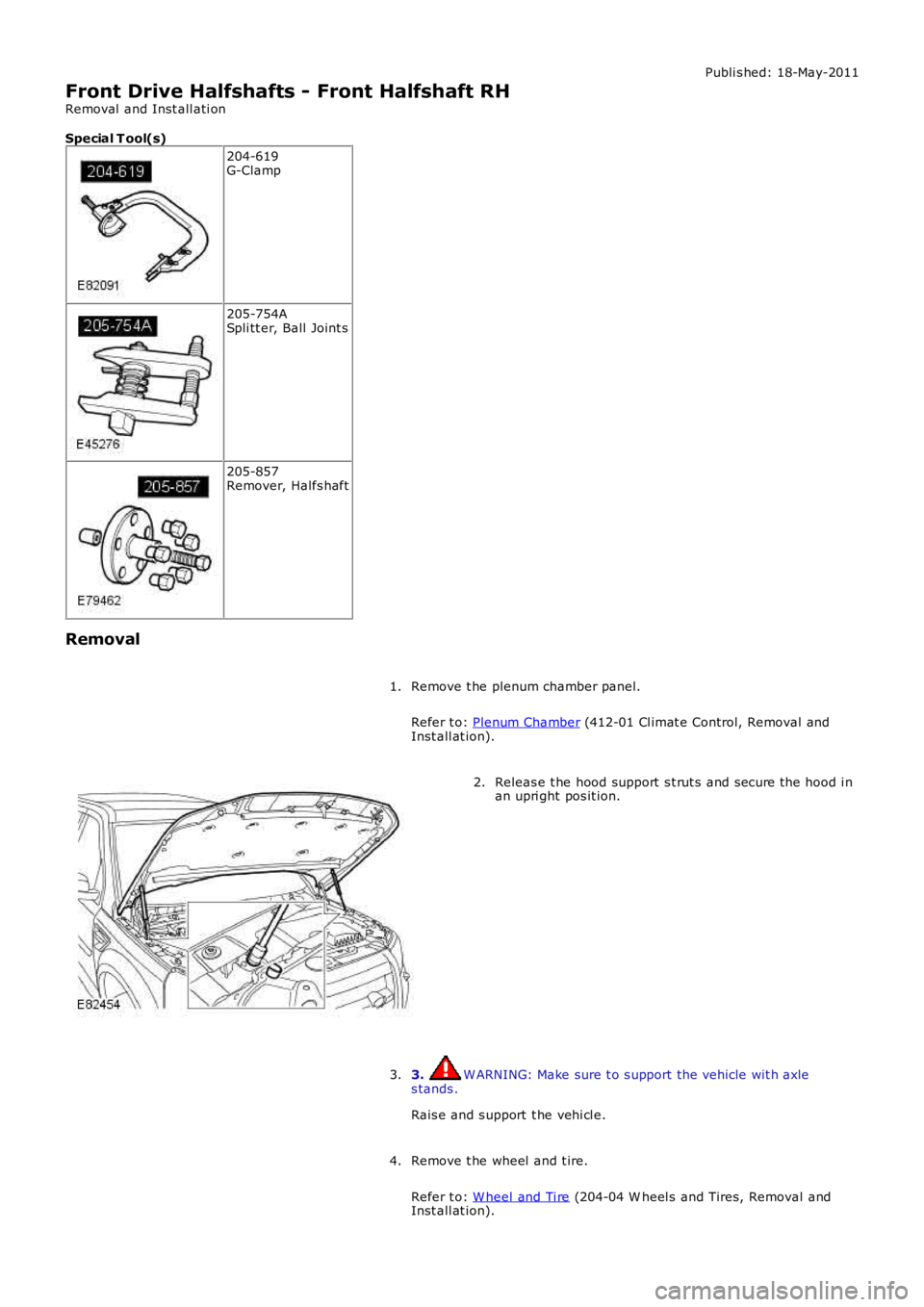
Special T ool(s) 204-619
G-Clamp 205-754A
Spli tt er, Ball Joint s 205-857
Remover, Halfs haft
Removal Remove t he plenum chamber panel.
Refer t o: Plenum Chamber (412-01 Cl imat e Control, Removal and
Inst all at ion).
1. Releas e t he hood support s t rut s and s ecure the hood i n
an upri ght pos it ion.
2.
3. W ARNING: Make sure t o s upport the vehicle wit h axle
s tands .
Rais e and s upport t he vehi cl e.
3.
Remove t he wheel and t ire.
Refer t o: W heel and Ti re (204-04 W heel s and Tires, Removal and
Inst all at ion).
4.
Page 382 of 3229
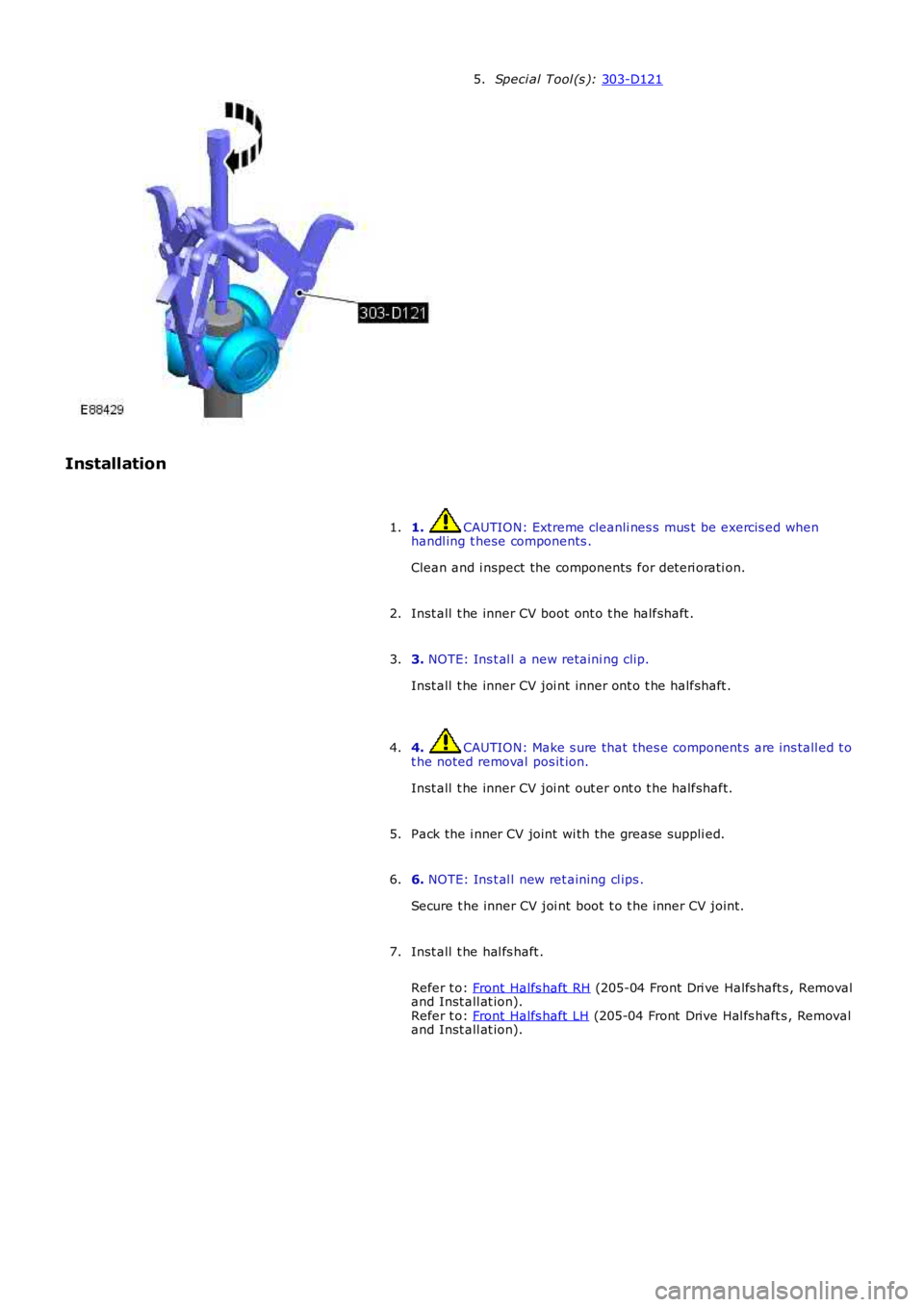
Speci al Tool (s ):
303-D121 5.
Installation 1. CAUTION: Extreme cleanli nes s mus t be exercis ed when
handl ing t hese components .
Clean and i nspect the components for det eri orati on.
1.
Inst all t he inner CV boot ont o t he halfshaft .
2.
3. NOTE: Ins t al l a new retaini ng clip.
Inst all t he inner CV joi nt inner ont o t he halfshaft .
3.
4. CAUTION: Make s ure that thes e component s are ins tall ed t o
t he noted removal pos it ion.
Inst all t he inner CV joi nt out er ont o t he halfshaft.
4.
Pack the i nner CV joint wi th the grease suppli ed.
5.
6. NOTE: Ins t al l new ret aining cl ips .
Secure t he inner CV joi nt boot t o t he inner CV joint.
6.
Inst all t he hal fs haft .
Refer t o: Front Halfs haft RH (205-04 Front Dri ve Halfs haft s , Removal
and Inst all at ion).
Refer t o: Front Halfs haft LH (205-04 Front Drive Hal fs haft s , Removal
and Inst all at ion).
7.
Page 385 of 3229
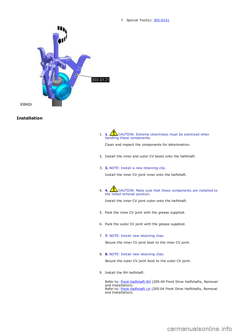
Speci al Tool (s ):
303-D121 7.
Installation 1. CAUTION: Extreme cleanli nes s mus t be exercis ed when
handl ing t hese components .
Clean and i nspect the components for det eri orati on.
1.
Inst all t he inner and out er CV boots ont o t he hal fs haft .
2.
3. NOTE: Ins t al l a new retaini ng clip.
Inst all t he inner CV joi nt inner ont o t he halfshaft .
3.
4. CAUTION: Make s ure that thes e component s are ins tall ed t o
t he noted removal pos it ion.
Inst all t he inner CV joi nt out er ont o t he halfshaft.
4.
Pack the i nner CV joint wi th the grease suppli ed.
5.
Pack the out er CV joi nt wit h t he grease s uppli ed.
6.
7. NOTE: Ins t al l new ret aining cl ips .
Secure t he inner CV joi nt boot t o t he inner CV joint.
7.
8. NOTE: Ins t al l new ret aining cl ips .
Secure t he outer CV joint boot to t he outer CV joint .
8.
Inst all t he RH halfs haft.
Refer t o: Front Halfs haft RH (205-04 Front Dri ve Halfs haft s , Removal
and Inst all at ion).
Refer t o: Front Halfs haft LH (205-04 Front Drive Hal fs haft s , Removal
and Inst all at ion).
9.
Page 394 of 3229
Stage 1:
Stage 2:
Secure t he parking brake cable.
8.
Support the weight of the vehicle us i ng a jack under the rear hub.
9.
10. CAUTIONS: Nut s and bolt s mus t be t ightened wi th the wei ght of t he
vehicle on the s us pens ion. Do not us e ai r tools to i nst all t he nut. Fail ure t o follow thi s
i ns t ructi on may resul t in damage t o t he component.
Tight en bot h l ower arm nut s and bolt s .
T orque: 175 Nm Tight en the trai li ng arm nut and bol t.
T orque: 270 Nm Tight en the rear hal fs haft nut .
T orque: 330 Nm 30°
St ake t he hub nut.10.
Inst all t he s tabil izer bar l ink.
Refer t o: Rear St abi li zer Bar Link (204-02 Rear Sus pensi on, Removal
and Inst all at ion).
11.
Inst all t he wheel and t ire.
Refer t o: W heel and Ti re (204-04 W heel s and Tires, Removal and
Inst all at ion).
12.
13. CAUTION: Do not fill t he different ial wi th lubri cant up t o
t he fi ll er pl ug. The fil ler plug i s only us ed t o fill t he different ial wi th
l ubricant , and not to act as a level i ndicat or.
Fil l the di fferenti al wi th the correct amount of l ubricant .
Refer t o: Different ial Drai ni ng and Fil ling (205-02 Rear Drive
Axle/Different ial, General Procedures).
13.
Page 399 of 3229
Stage 1:
Stage 2:
Secure t he parking brake cable.
8.
Support the weight of the vehicle us i ng a jack under the rear hub.
9.
10. CAUTIONS: Nut s and bolt s mus t be t ightened wi th the wei ght of t he
vehicle on the s us pens ion. Do not us e ai r tools to i nst all t he nut. Fail ure t o follow thi s
i ns t ructi on may resul t in damage t o t he component.
Tight en bot h l ower arm nut s and bolt s .
T orque: 175 Nm Tight en the trai li ng arm nut and bol t.
T orque: 270 Nm Tight en the rear hal fs haft nut .
T orque: 330 Nm 30°
St ake t he hub nut.10.
Inst all t he s tabil izer bar l ink.
Refer t o: Rear St abi li zer Bar Link (204-02 Rear Sus pensi on, Removal
and Inst all at ion).
11.
Inst all t he wheel and t ire.
Refer t o: W heel and Ti re (204-04 W heel s and Tires, Removal and
Inst all at ion).
12.
13. CAUTION: Do not fill t he different ial wi th lubri cant up t o
t he fi ll er pl ug. The fil ler plug i s only us ed t o fill t he different ial wi th
l ubricant , and not to act as a level i ndicat or.
Fil l the di fferenti al wi th the correct amount of l ubricant .
13.
Page 401 of 3229
5.
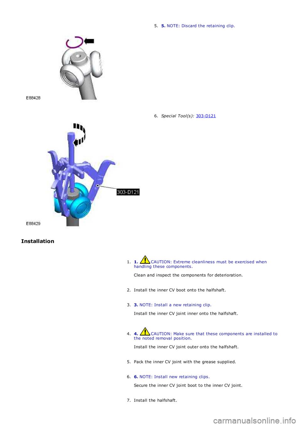
NOTE: Dis card t he ret aining cl ip.
5. Speci al Tool (s ):
303-D121 6.
Installation 1. CAUTION: Extreme cleanli nes s mus t be exercis ed when
handl ing t hese components .
Clean and i nspect the components for det eri orati on.
1.
Inst all t he inner CV boot ont o t he halfshaft .
2.
3. NOTE: Ins t al l a new retaini ng clip.
Inst all t he inner CV joi nt inner ont o t he halfshaft .
3.
4. CAUTION: Make s ure that thes e component s are ins tall ed t o
t he noted removal pos it ion.
Inst all t he inner CV joi nt out er ont o t he halfshaft.
4.
Pack the i nner CV joint wi th the grease suppli ed.
5.
6. NOTE: Ins t al l new ret aining cl ips .
Secure t he inner CV joi nt boot t o t he inner CV joint.
6.
Inst all t he hal fs haft .
7.
Page 405 of 3229
t he noted removal pos it ion.
Inst all t he inner CV joi nt out er ont o t he halfshaft.
Pack the i nner CV joint wi th the grease suppli ed.5.
Pack the out er CV joi nt wit h t he grease s uppli ed.6.
7. NOTE: Ins t al l new ret aining cl ips .
Secure t he inner CV joi nt boot t o t he inner CV joint.
7.
8. NOTE: Ins t al l new ret aining cl ips .
Secure t he outer CV joint boot to t he outer CV joint .
8.
Inst all t he hal fs haft .
Refer t o: Rear Hal fs haft LH (205-05 Rear Dri ve Halfs haft s , Removaland Inst all at ion).
9.
Page 415 of 3229
1
1
2
3
4
5
6
1
1
2
3
4
5
1
Check t he brake mas ter cylinder res ervoir flui d level.
Is t he fl uid l evel OK?YesGO t o J3.NoCHECK brake mas ter cyl inder res ervoir s ealing poi nts . For addit ional informat ion, refer t o Brakemast er cyl inder component t es t in t his secti on. ADD brake fluid and BLEED t he brake s ys tem.REFER t o: Brake Syst em Bl eedi ng (206-00 Brake Syst em - General Informati on, General Procedures )/Brake Sys t em Pres s ure Bleedi ng (206-00 Brake Sys tem - General Informati on, General Procedures ).TEST t he s yst em for normal operati on. REPEAT road tes t if neces s ary.J3: CHECK BRAKE PEDAL RESERVE
Run engine at idle speed.
Apply the brake pedal li ght ly three or four ti mes .
W ait 15 s econds for the vacuum t o repl eni sh.
Pus h down on t he brake pedal unt il i t s tops moving downward or an increas ed res is t ance t o t hebrake pedal t ravel occurs .
Hol d t he brake pedal i n t he appl ied pos it ion whi le i ncreas i ng the engine speed t o 2000 rpm.
Rel eas e t he accel erator pedal .
Does t he brake pedal move downward as t he engi ne s peed returns to idle?YesGO t o J4.NoCHECK the vacuum t o the brake boos t er.
J4: CHECK T HE FRO NT WHEEL BEARING ASSEMBLY
Check t he front wheel bearing as s embly.
Are t he front wheel beari ngs l oose?YesINSTALL a new front wheel beari ng if damaged.REFER t o: Front W heel Bearing (204-01 Front Suspens ion, Removal and Inst all at ion).TEST t he s yst em for normal operati on.NoCHECK the front brake di scs for thicknes s variances .
PINPOINT TEST K : SLOW OR INCOMPLETE BRAKE PEDAL RETU RN
T ESTCONDIT IO NSDET AILS/RESULT S/ACT IO NS
K1: CHECK FOR BRAKE PEDAL RET URN
Run the engine at i dle whi le maki ng s everal brake appli cat ions .
Pul l the brake pedal rearward wi th approxi matel y 44.5 N (10lb) force.
Rel eas e t he brake pedal and measure t he dis tance t o t he toe board.
Make a hard brake appl icat ion.
Rel eas e t he brake pedal and measure t he brake pedal t o t oe board di st ance. The brake pedalshould return t o it s original posi ti on.
Does t he brake pedal return t o it s original posi ti on?YesVehi cl e is OK.NoGO t o K2.
K2: CHECK FOR BRAKE PEDAL BINDINGDis connect t he brake boos ter from the brake pedal. Check t he brake pedal t o ens ure freeoperat ion.
Is t he brake pedal operat ing freel y?YesINSTALL a new brake boos ter.REFER t o: Brake Boost er (206-07 Power Brake Act uat ion, Removal and Ins tall ati on).TEST t he s yst em for normal operati on.NoREPAIR or INSTALL new brake pedal. TEST t he s ys t em for normal operati on.
Component Tests
Brake Booster
1. Check al l hos es and connecti ons . All unus ed vacuum connect ors s houl d be capped. Hos es and thei r connect ionss hould be correctl y s ecured and in good condi ti on wit h no hol es and no col laps ed areas. Ins pect t he val ve on t hebrake boos ter for damage.
1.
2. Check t he hydraulic brake s ys t em for leaks or low flui d.2.
3. W i th the aut omat ic trans mi s si on in PARK, s t op the engine and apply the parki ng brake. Pump t he brake pedals everal ti mes t o exhaus t all vacuum in the s ys tem. W it h t he engi ne s wit ched off and al l vacuum i n t he s ys t emexhaus t ed, apply the brake pedal and hold i t down. St art t he engi ne. If t he vacuum sys tem is operat ing, t hebrake pedal wil l tend t o move downward under cons t ant foot pres sure. If no mot ion is felt , the vacuum boos t ers ys tem is not funct ioning.
3.
4. Remove the vacuum hos e from t he brake boos ter. Mani fol d vacuum should be avai lable at t he brake boos ter endof t he hose wit h t he engi ne at idl e s peed and t he automat ic trans mi ss i on in PARK. Make s ure that all unusedvacuum outl ets are correct ly capped, hos e connectors are correct ly secured and vacuum hoses are i n goodcondit ion. W hen it is es tabli s hed that manifold vacuum is avai lable t o t he brake boos ter, connect t he vacuumhos e t o t he brake boost er and repeat St ep 3. If no downward movement of the brake pedal is felt , ins tal l a new
4.
Page 417 of 3229
Publi s hed: 11-May-2011
Brake System - General Information - Brake System Bleeding
General Procedures
W ARNING: If any component s upst ream of the Hydraul ic Control Uni t (HCU), including the HCU it sel f are replaced,t he brake s ys t em mus t be bl ed usi ng Land Rover approved diagnos t ic equipment . Thi s wil l ens ure that all ai r is expelledfrom the new component (s).
• NOTE: The fol lowi ng procedure covers bleedi ng t he brake s yst em i f components down st ream of the HCU have beenrepl aced. W here onl y t he primary or s econdary brake ci rcuit s have been di s turbed in i sol ati on, i t should onl y be neces s aryt o bleed t hat ci rcuit . Parti al bl eedi ng of the hydrauli c s ys t em i s only permis s ible if a brake tube or hos e has beendis connected wi th onl y mi nimal los s of fluid.
1. W ARNING: Do not work on or under a vehi cle s upported onl yby a jack. Al ways support t he vehi cl e on s afet y s tands .
Rais e and s upport t he vehi cl e.
1.
Check that t he brake fl uid l ines are s ecure and that t here are nos igns of a brake fl ui d l eak. If a brake fluid leak is det ect ed,i nves ti gat e and rect ify t he caus e of t he leak before bleeding t hebrakes .
Refer t o: Brake Syst em (206-00 Brake Sys t em - General Informat ion,Di agnos is and Tes ti ng).
2.
Pump t he brake pedal unt il t he brake vacuum ass i st ance isexhaus t ed.3.
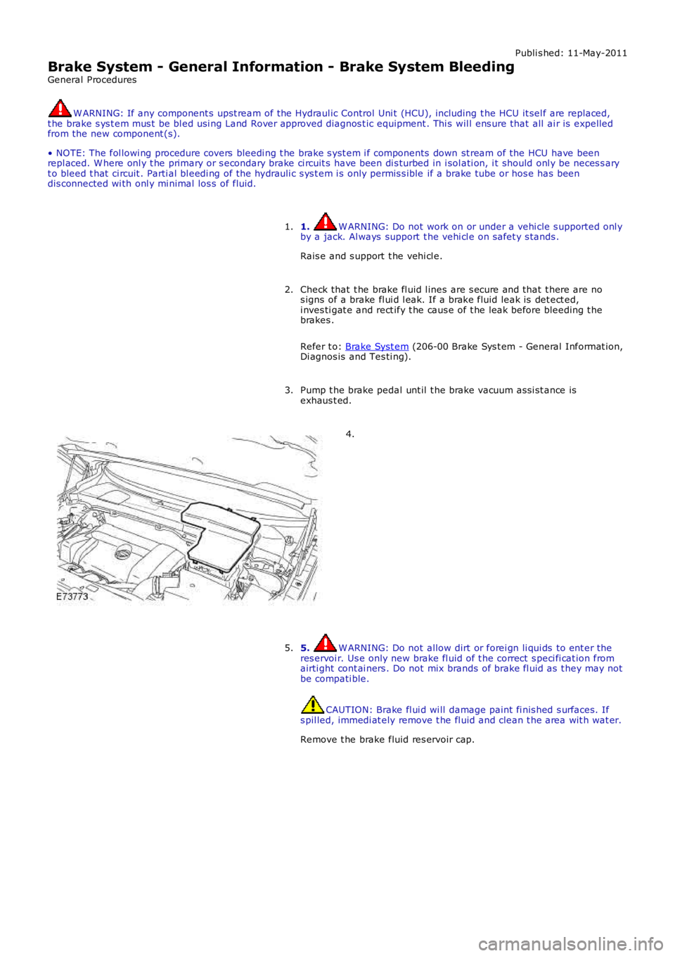
4.
5. W ARNING: Do not allow dirt or forei gn li qui ds to ent er theres ervoi r. Us e only new brake fl uid of t he correct s peci fi cat ion fromairti ght cont ai ners . Do not mix brands of brake fl uid as t hey may notbe compati ble.
CAUTION: Brake fl ui d wi ll damage paint fi nis hed s urfaces. Ifs pil led, immedi at ely remove t he fl uid and clean t he area wit h wat er.
Remove t he brake fluid res ervoir cap.
5.
Page 422 of 3229
3-Dus t s hiel d
4-Dus t s hiel d ret aining s crew (3 off)
5-Brake dis c6-Brake dis c ret aini ng screw
7-Outer anti -s queal s him
8-Outer brake pad9-Inner brake pad
10-Inner ant i-s queal s him
11-Cal iper hous i ng spring12-Fi xed carri er
13-Cal iper pis ton seal
14-Cal iper pis ton15-Sl idi ng cal iper
16-Bus hed bolt rubber boot (2 off)
17-Bus hed bolt (2 off)18-Bus hed bolt dus t cap (2 off)
19-Cal iper bleed s crew
20-Bleed s crew cap21-Fl exi ble hos e
22-Fi xed carri er retai ni ng bolt (2 off)
23-Front Left-Hand (LH) wheel knuckle
OVERVIEW
The front brake as sembl y feat ures a venti lat ed brake dis c and cast -iron sl idi ng cal iper wit h s ingle act ing pi st on.
BRAKE DISC
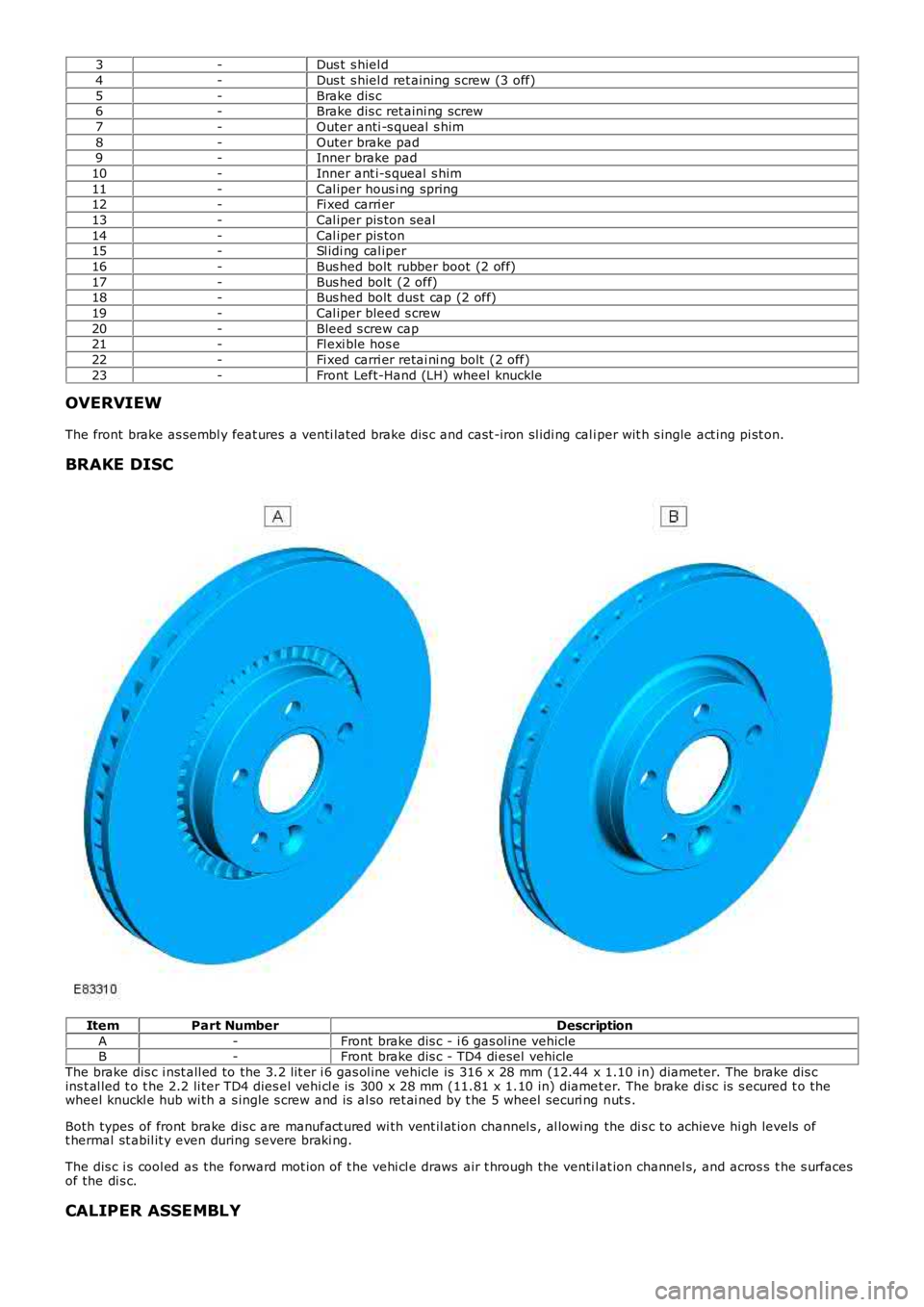
ItemPart NumberDescription
A-Front brake dis c - i 6 gas ol ine vehicleB-Front brake dis c - TD4 di esel vehicle
The brake dis c i nst all ed to the 3.2 l it er i 6 gas ol ine vehicle is 316 x 28 mm (12.44 x 1.10 i n) diameter. The brake dis cins t al led t o t he 2.2 li ter TD4 dies el vehi cl e is 300 x 28 mm (11.81 x 1.10 in) diamet er. The brake di sc is s ecured t o thewheel knuckl e hub wi th a s ingle s crew and is al so ret ai ned by t he 5 wheel securi ng nut s .
Both types of front brake dis c are manufact ured wi th vent il at ion channel s , al lowi ng the di s c to achieve hi gh levels oft hermal st abil it y even during s evere braki ng.
The dis c i s cool ed as the forward mot ion of t he vehi cl e draws air t hrough the venti lat ion channel s, and acros s t he s urfacesof the di s c.
CALIPER ASSEMBLY