ECU LAND ROVER FRELANDER 2 2006 Owner's Manual
[x] Cancel search | Manufacturer: LAND ROVER, Model Year: 2006, Model line: FRELANDER 2, Model: LAND ROVER FRELANDER 2 2006Pages: 3229, PDF Size: 78.5 MB
Page 174 of 3229
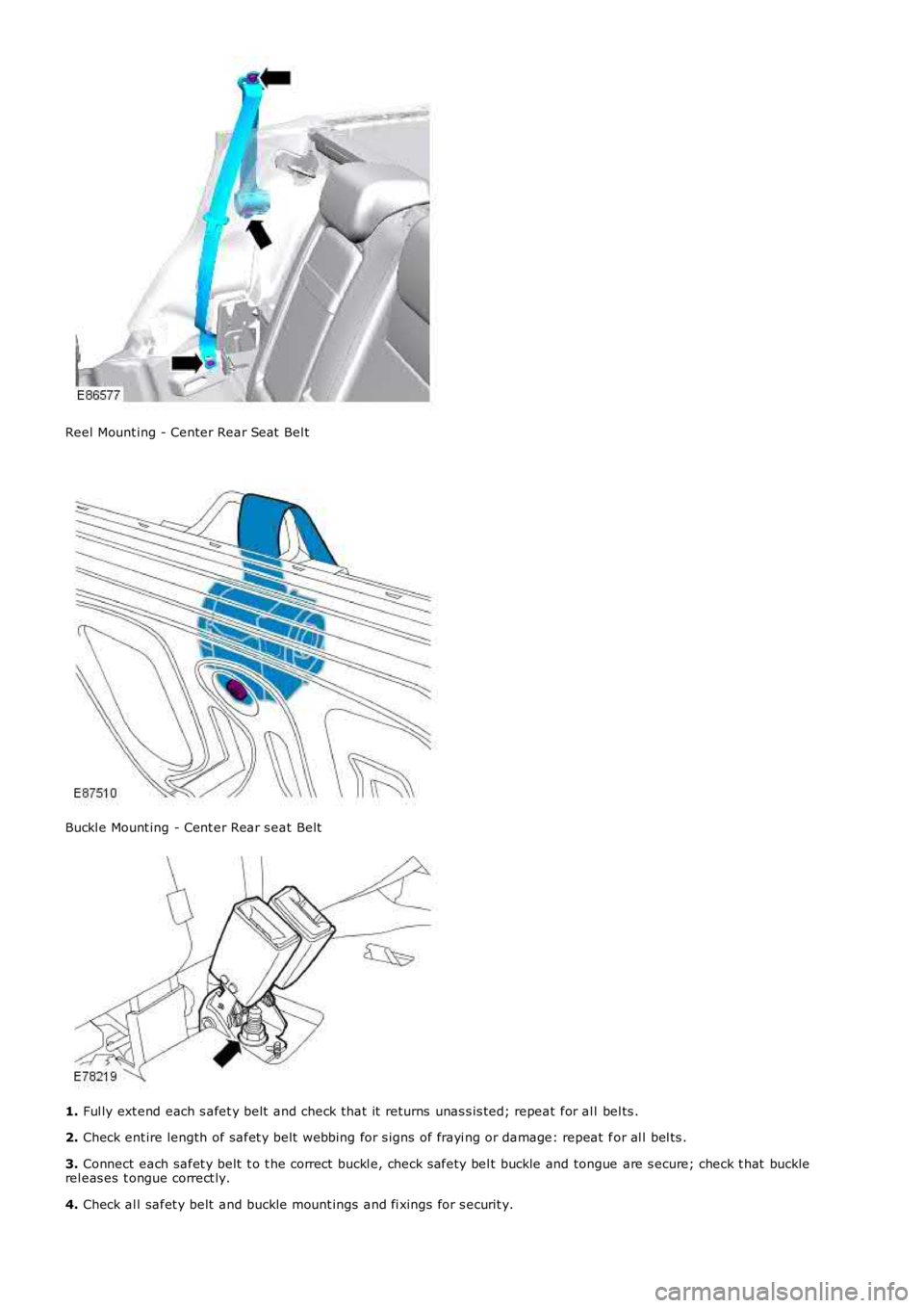
Reel Mount ing - Center Rear Seat Bel t
Buckl e Mount ing - Cent er Rear s eat Belt
1. Ful ly ext end each s afet y belt and check that it returns unas s is ted; repeat for al l bel ts .
2. Check ent ire length of safet y belt webbing for s igns of frayi ng or damage: repeat for al l bel ts .
3. Connect each safet y belt t o t he correct buckl e, check s afety bel t buckle and tongue are s ecure; check t hat bucklerel eas es t ongue correct ly.
4. Check al l safet y belt and buckle mount ings and fi xings for s ecurit y.
Page 175 of 3229
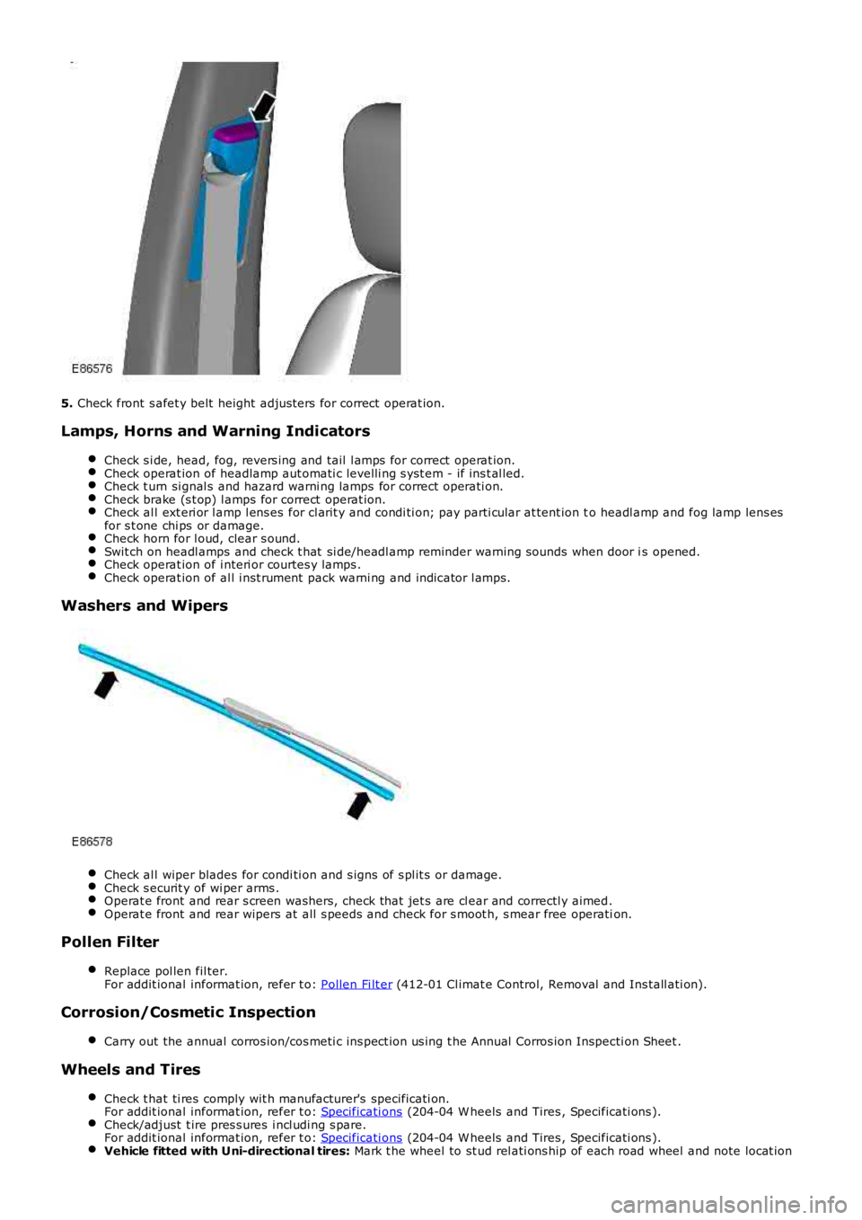
5. Check front s afet y belt height adjus ters for correct operat ion.
Lamps, Horns and Warning Indicators
Check s i de, head, fog, revers ing and tail l amps for correct operat ion.Check operat ion of headlamp aut omati c levelli ng s yst em - if ins t al led.Check t urn si gnal s and hazard warni ng lamps for correct operati on.Check brake (s t op) l amps for correct operat ion.Check al l ext eri or l amp l ens es for cl arit y and condi ti on; pay parti cular at tent ion to headl amp and fog lamp lens esfor s t one chi ps or damage.Check horn for l oud, clear s ound.Swit ch on headl amps and check t hat si de/headl amp reminder warning s ounds when door is opened.Check operat ion of i nteri or courtes y lamps .Check operat ion of al l i nst rument pack warni ng and indicator l amps.
Washers and Wipers
Check al l wiper blades for condi ti on and s igns of s pl it s or damage.Check s ecurit y of wi per arms .Operat e front and rear s creen washers, check that jet s are cl ear and correctl y aimed.Operat e front and rear wipers at all s peeds and check for s moot h, s mear free operation.
Pollen Filter
Replace pol len fil ter.For addit ional informat ion, refer t o: Pollen Fi lt er (412-01 Cl imat e Control, Removal and Ins tall ati on).
Corrosion/Cosmetic Inspection
Carry out the annual corros ion/cos meti c ins pect ion us ing t he Annual Corros ion Inspecti on Sheet .
Wheels and Tires
Check t hat ti res comply wit h manufacturer's specificati on.For addit ional informat ion, refer t o: Specificati ons (204-04 W heels and Tires , Specificati ons ).Check/adjust t ire pres s ures i ncl udi ng s pare.For addit ional informat ion, refer t o: Specificati ons (204-04 W heels and Tires , Specificati ons ).Vehicle fitted with Uni-directional tires: Mark t he wheel to st ud rel ati ons hip of each road wheel and note locat ion
Page 180 of 3229
1. Check for free play i n all s uspens ion and body mounti ng rubbers .
2. Check condit ion of s uspens ion rubber boot s and gait ers .
Fuel System
Check fuel sys tem pipes , hos es and unions for chafi ng, l eaks and corros ion.
Electrical Harnesses
Check al l el ect ri cal harnes s es for chafing.
Oil/Fluid Leaks
Check for oil/fluid leaks .
Power Steering
Check power s teering rod bal l joi nt fixi ngs , gait ers and condi ti on of bal l joi nt s and dus t covers .Check power s teering pipes , hos es and unions for chafi ng, leaks and corros ion.
Exhaust System
Check exhaust s ys tem for l eaks , securi ty and damage.
Fault Lamp(s)
If fault l amp(s ) are ill uminat ed, t est the as s oci at ed s yst em us i ng T4 and report findings .
Road Test
Carry out road t est of vehicle.For addit ional informat ion, refer t o: Road/Roller Tes ti ng (100-00 General Informati on, Des cri pt ion and Operati on).
General
Endors e Service Record.Report any unus ual features of vehi cl e condi ti on and any addi ti onal work required.
Vehicles Operating Under Arduous Conditions
Service i ntervals for vehi cles operati ng under arduous condi ti ons are det ailed bel ow.
Braking system
CAUTION: When vehicles are operating under arduous conditions, the following service items must be carriedout every 3 months or 3,750 miles (6,000 km).
Ins pect front brake pads for wear.Ins pect rear pads for wear.Check brake cal ipers for s igns of fl ui d l eaks .Check brake dis cs for condi ti on.Check al l brake boos t er and brake s ys t em pipes and hos es for condi ti on, chafi ng and leaks.Clean road wheel hub s pigot s and appl y greas e, Land Rover Part Number RY L 105020 t o t he wheel mat ing surfaceof each s pigot .
Brake Fluid Replacement
CAUTION: When vehicles are operating under arduous conditions, the following service item must be carried outevery 2 Years or 30,000 miles (48,000 km).
Replace brake fluid.
Road Wheel Speed Sensors
CAUTION: When vehicles are operating under arduous conditions, the following service item must be carried outevery 3 months or 3,750 miles (6,000 km).
Ins pect the road wheel s peed s ens or harness es for damage.
Engine Oil and Filter
CAUTION: When vehicles are operating under arduous conditions, the following service item must be carried outevery 3 months or 3,750 miles (6,000 km).
Renew engi ne oil and fil ter.
Page 183 of 3229
Check condit ion of batt ery.
Check/top up bat tery electrolyte level .
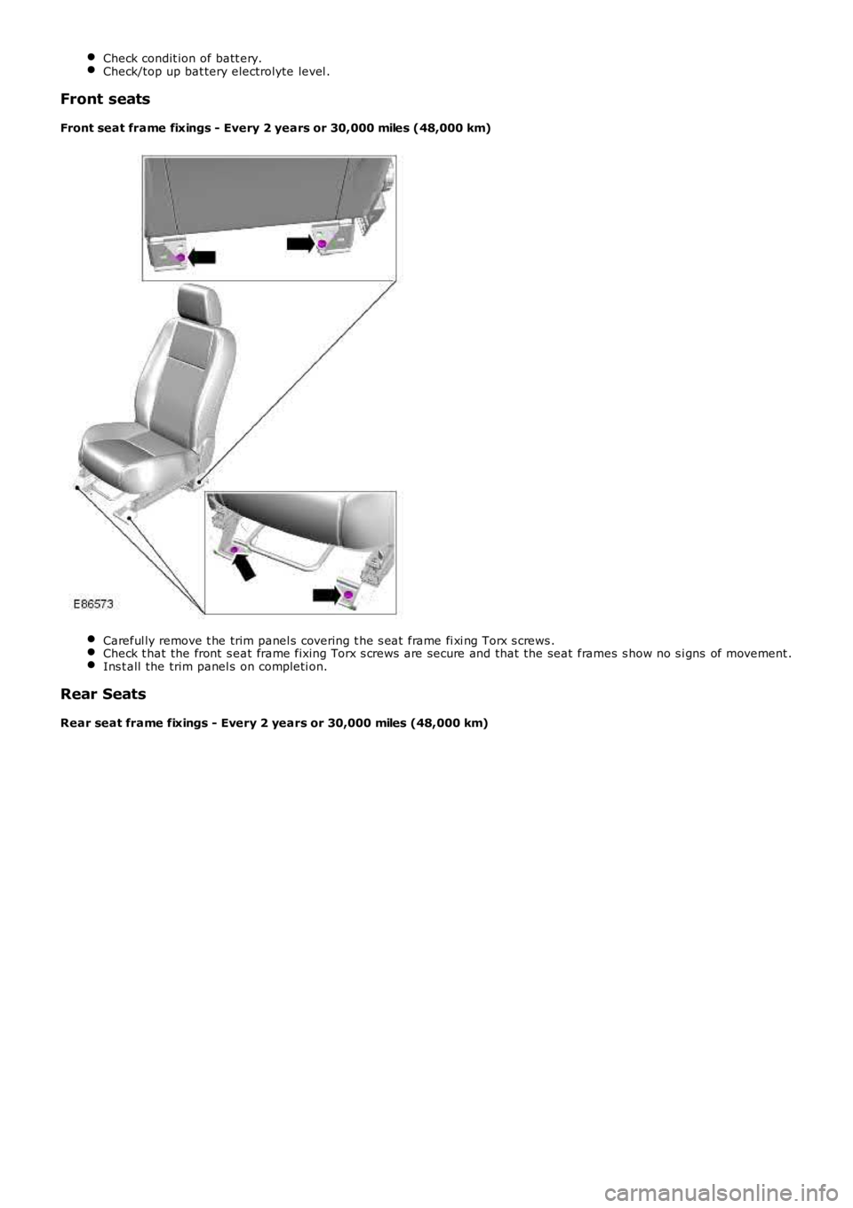
Front seats
Front seat frame fixings - Every 2 years or 30,000 miles (48,000 km) Careful ly remove t he trim panel s covering t he s eat frame fi xi ng Torx s crews .
Check t hat the front s eat frame fixing Torx s crews are secure and that the seat fram
es s how no s i gns of movement .Ins t all the trim panel s on completi on.
Rear Seats
Rear seat frame fixings - Every 2 years or 30,000 miles (48,000 km)
Page 184 of 3229
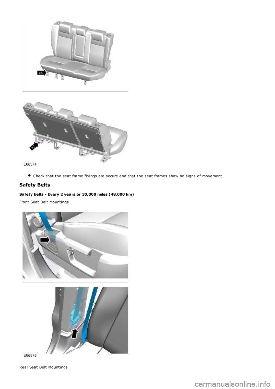
Check t hat the seat frame fixi ngs are s ecure and t hat t he s eat frames s how no s igns
of movement .Safety Belts
Safety belts - Every 2 years or 30,000 miles (48,000 km)
Front Seat Bel t Mount ings Rear Seat Belt Mount ings
Page 185 of 3229
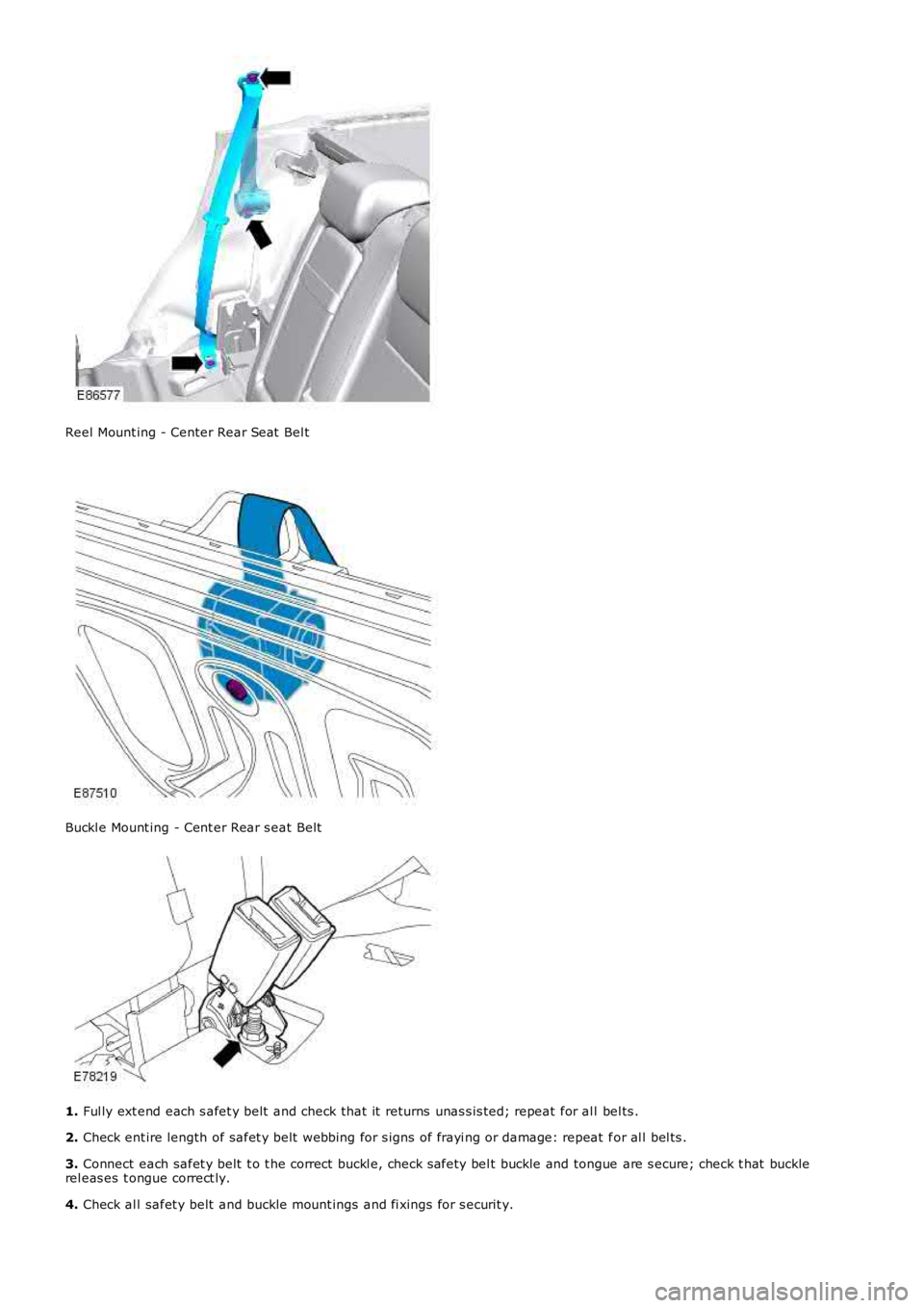
Reel Mount ing - Center Rear Seat Bel t
Buckl e Mount ing - Cent er Rear s eat Belt
1.
Ful ly ext end each s afet y belt and check that it returns unas s is ted; repeat for al l bel ts .
2. Check ent ire length of safet y belt webbing for s igns of frayi ng or damage: repeat f or al l bel ts .
3. Connect each safet y belt t o t he correct buckl e, check s afety bel t buckle and tongue are s ecure; check t hat buckle
rel eas es t ongue correct ly.
4. Check al l safet y belt and buckle mount ings and fi xings for s ecurit y.
Page 186 of 3229
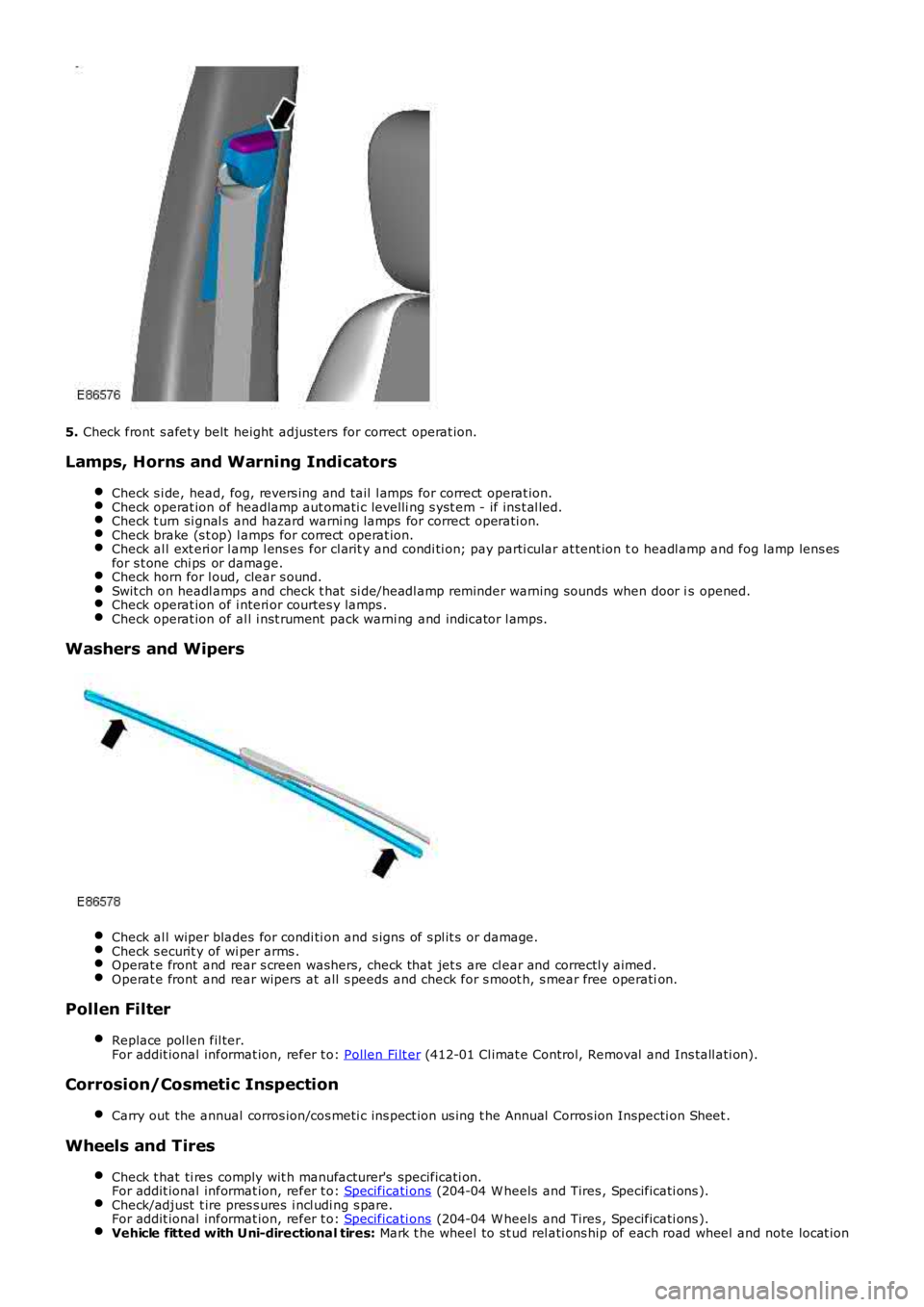
5.
Check front s afet y belt height adjus ters for correct operat ion.
Lamps, Horns and Warning Indicators Check s i de, head, fog, revers ing and tail l amps for correct operat ion. Check operat ion of headlamp aut omati c levelli ng s yst em - if ins t al led.
Check t urn si gnal s and hazard warni ng lamps for correct operati on.
Check brake (s t op) l amps for correct operat ion.
Check al l ext eri or l amp l ens es for cl arit y and condi ti on; pay parti cular at tent ion t
o headl amp and fog lamp lens es
for s t one chi ps or damage. Check horn for l oud, clear s ound.
Swit ch on headl amps and check t hat si de/headl amp reminder warning s ounds when door i
s opened.Check operat ion of i nteri or courtes y lamps .
Check operat ion of al l i nst rument pack warni ng and indicator l amps.
Washers and Wipers
Check al l wiper blades for condi ti on and s igns of s pl it s or damage.
Check s ecurit y of wi per arms .
Operat e front and rear s creen washers, check that jet s are cl ear and correctl y aimed
.Operat e front and rear wipers at all s peeds and check for s moot h, s mear free operati
on.Pollen Filter
Replace pol len fil ter.
For addit ional informat ion, refer t o: Pollen Fi lt er (412-01 Cl imat e Control, Removal and Ins tall ati on).
Corrosion/Cosmetic Inspection
Carry out the annual corros ion/cos meti c ins pect ion us ing t he Annual Corros ion Inspec ti on Sheet .Wheels and Tires
Check t hat ti res comply wit h manufacturer's specificati on.
For addit ional informat ion, refer t o: Specificati ons (204-04 W heels and Tires , Specificati ons ).
Check/adjust t ire pres s ures i ncl udi ng s pare.
For addit ional informat ion, refer t o: Specificati ons (204-04 W heels and Tires , Specificati ons ).
Vehicle fitted with Uni-directional tires:
Mark t he wheel to st ud rel ati ons hip of each road wheel and note locat ion
Page 191 of 3229
For addit ional informat ion, refer t o: Specificati ons (307-01 Aut omati c Trans mis s ion/Transaxle, Speci fi cat ions ).
Manual Transmission
Every 10 years or 150,000 miles (240,000 km): Renew manual t rans mi ss ion fl ui d.
For addit ional informat ion, refer t o: Specificati ons (308-00 Manual Trans mis s ion/Transaxle and Clutch - General
Informat ion, Speci ficat ions).
Power Transfer Unit
Every 10 years or 150,000 miles (240,000 km): Renew power t rans fer unit oi l. For addi ti onal informat ion, refer to:
(308-07B Transfer Case)
Power Trans fer Uni t - TD4 2.2L Di esel , Vehi cl es W i th: M66 6-Speed Manual Trans mis s io n AW D (Removal and
Ins tal lat ion),
Power Trans fer Uni t - TD4 2.2L Di esel , Vehi cl es W i th: M66 6-Speed Manual Trans mis s io n AW D (Removal and
Ins tal lat ion).
Differential Assembly - Rear
Every 10 years or 150,000 miles (240,000 km): Renew rear different ial oil .
For addit ional informat ion, refer t o: Specificati ons (205-02 Rear Drive Axle/Different ial, Specifi cat ions ).
Suspension and Body Mountings Check for free play i n all s us pens ion and body mounti ng rubbers . Check condit ion of s uspens ion rubber boots and gait ers .
Fuel System
Check fuel sys tem pipes , hos es and unions for chafi ng, l eaks and corros ion. Electrical Harnesses
Check al l el ect ri cal harnes s es for chafing. Oil/Fluid Leaks
Check for oil/fluid leaks . Power Steering
Check power s teering rod bal l joi nt fixi ngs , gait ers and condi ti on of bal l joi nt s an d dus t covers .Check power s teering pipes , hos es and unions for chafi ng, leaks and corros ion.
Exhaust System
Check exhaust s ys tem for l eaks , securi ty and damage. Clutch
1. Check clut ch pipes and unions for chafi ng, l eaks and corrosi on.
Fault Lamp(s) If fault l amp(s ) are ill uminat ed, t est the as s oci at ed s yst em us i ng Land Rover approv ed di agnos ti c equipment and
report findi ngs . Road Test
Carry out road t est of vehicle.
For addit ional informat ion, refer t o: Road/Roller Tes ti ng (100-00 General Informati on, Des cri pt ion and Operati on).
General
Endors e Service Record. Report any unus ual features of vehi cl e condi ti on and any addi ti onal work required.
Vehicles Operating Under Arduous Conditions
Recommended s ervi ce interval s for vehicles operat ing under arduous condit ions are de t ail ed below.
Braking System CAUTION:
When vehicles are operating under arduous conditions, the following service items mu st be carried
out every 3 months or 3,750 miles (6,000 km).
Ins pect front brake pads for wear.
Page 200 of 3229
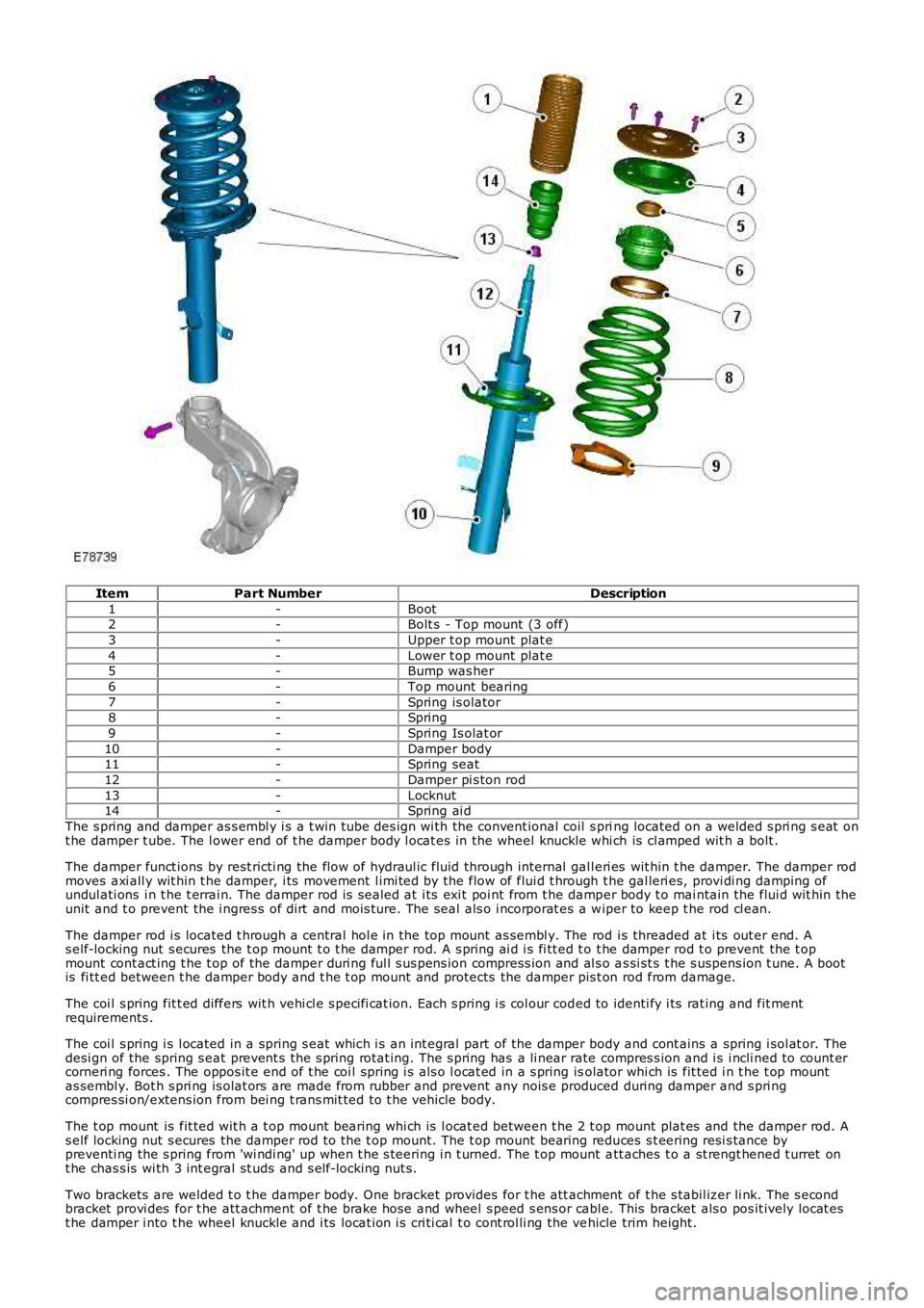
ItemPart NumberDescription
1-Boot2-Bolt s - Top mount (3 off)
3-Upper t op mount plat e
4-Lower t op mount plat e5-Bump was her
6-Top mount bearing
7-Spring is olator8-Spring
9-Spring Is olat or
10-Damper body11-Spring seat
12-Damper pi s ton rod
13-Locknut14-Spring ai d
The s pring and damper as s embl y i s a t win tube des ign wi th the convent ional coil s pring located on a welded s pri ng s eat ont he damper t ube. The l ower end of t he damper body l ocat es in the wheel knuckle whi ch is cl amped wit h a bolt .
The damper funct ions by rest ricti ng the flow of hydraul ic fluid through internal gall eri es wit hin t he damper. The damper rodmoves axi all y wit hin t he damper, i ts movement l imi ted by the flow of flui d t hrough the gal leri es, provi di ng damping ofundul ati ons i n t he t errai n. The damper rod is s ealed at i ts exi t poi nt from t he damper body t o mai ntain the flui d wit hin theunit and t o prevent the i ngres s of dirt and mois ture. The seal als o i ncorporat es a wiper to keep t he rod cl ean.
The damper rod i s located t hrough a central hol e in the top mount as sembl y. The rod i s threaded at i ts out er end. As elf-locking nut s ecures the t op mount t o t he damper rod. A s pring ai d i s fi tt ed t o t he damper rod t o prevent the t opmount cont act ing t he t op of the damper duri ng ful l s us pens ion compress ion and al s o as si st s t he s uspens ion t une. A bootis fi tt ed between t he damper body and t he t op mount and protects the damper pis t on rod from damage.
The coi l s pring fit t ed differs wit h vehi cl e s peci fi cat ion. Each s pring i s col our coded to identi fy i ts rat ing and fit mentrequirements .
The coi l s pring i s l ocated in a spring s eat which i s an int egral part of the damper body and cont ains a spring i sol at or. Thedesi gn of the spring s eat prevent s t he s pring rotat ing. The s pring has a li near rate compres s ion and i s i ncli ned to count ercorneri ng forces . The oppos it e end of t he coi l spring i s als o l ocat ed in a s pring isolator whi ch is fit ted i n t he t op mountas sembl y. Bot h s pri ng is olat ors are made from rubber and prevent any nois e produced during damper and s pri ngcompres si on/extens ion from bei ng t rans mit ted to t he vehicle body.
The t op mount is fit ted wit h a t op mount bearing whi ch is l ocat ed between t he 2 t op mount plat es and the damper rod. As elf locking nut s ecures the damper rod to the t op mount. The t op mount bearing reduces s t eering resi s tance bypreventi ng the s pring from 'wi ndi ng' up when t he s teering i n t urned. The t op mount att aches t o a st rengt hened t urret ont he chas s is wi th 3 int egral st uds and s elf-locking nut s.
Two brackets are welded t o t he damper body. One bracket provides for t he att achment of t he s tabil izer li nk. The s econdbracket provi des for t he att achment of t he brake hose and wheel s peed s ens or cabl e. This bracket als o pos it ively locat est he damper i nto t he wheel knuckle and i ts locat ion i s cri ti cal t o cont rol li ng the vehicle trim height.
Page 201 of 3229
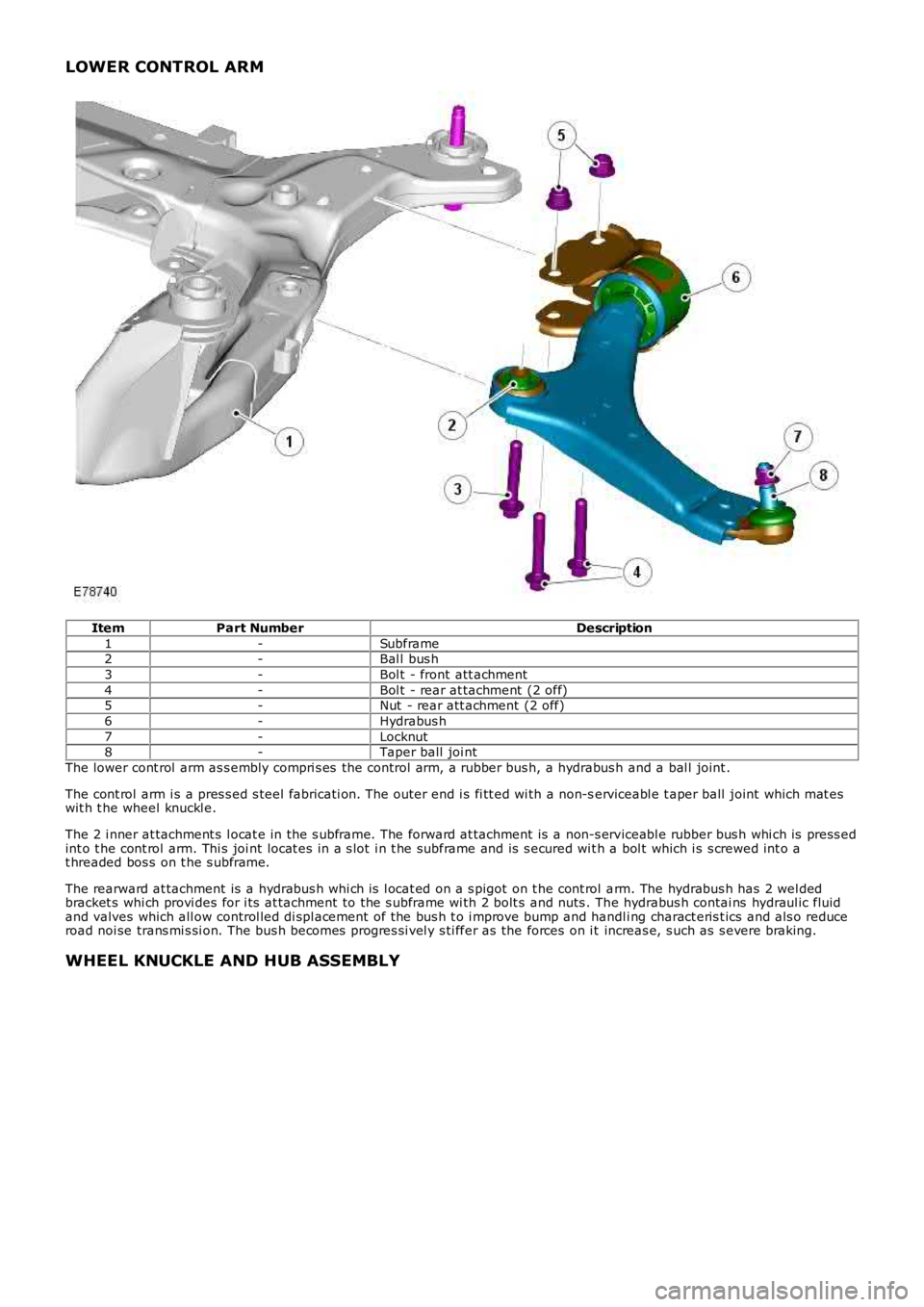
LOWER CONTROL ARM
ItemPart NumberDescription
1-Subframe2-Bal l bus h
3-Bol t - front att achment
4-Bol t - rear at tachment (2 off)5-Nut - rear att achment (2 off)
6-Hydrabus h
7-Locknut8-Taper ball joi nt
The lower cont rol arm as s embly compri s es the control arm, a rubber bus h, a hydrabus h and a bal l joint .
The cont rol arm i s a pres s ed s teel fabricati on. The outer end i s fi tt ed wi th a non-serviceabl e t aper ball joint which mat eswit h t he wheel knuckl e.
The 2 i nner at tachment s l ocat e in the s ubframe. The forward at tachment is a non-s erviceabl e rubber bus h whi ch is press edint o t he cont rol arm. Thi s joi nt locat es in a s lot i n t he subframe and is s ecured wit h a bol t which i s s crewed int o at hreaded bos s on t he s ubframe.
The rearward at tachment is a hydrabus h whi ch is l ocat ed on a s pigot on t he cont rol arm. The hydrabus h has 2 wel dedbracket s whi ch provi des for i ts at tachment to the s ubframe wi th 2 bolt s and nuts . The hydrabus h contai ns hydraul ic fluidand valves which all ow control led di spl acement of the bus h t o i mprove bump and handli ng charact eris t ics and als o reduceroad noi se trans mi s si on. The bus h becomes progres si vel y s ti ffer as the forces on i t increas e, s uch as s evere braking.
WHEEL KNUCKLE AND HUB ASSEMBLY