climate control LAND ROVER FRELANDER 2 2006 Repair Manual
[x] Cancel search | Manufacturer: LAND ROVER, Model Year: 2006, Model line: FRELANDER 2, Model: LAND ROVER FRELANDER 2 2006Pages: 3229, PDF Size: 78.5 MB
Page 10 of 3229
Publi s hed: 11-May-2011
General Information - How To Use This Manual
Des cript ion and Operat ion
Copyright Statement
Copyright.© Land Rover Ltd., 2006
All rights res erved. No part of thi s publ icati on may be reproduced, s tored in a ret ri eval s yst em or t rans mit t ed in any form,electroni c, mechanical, photocopyi ng, recordi ng or other means, wi thout pri or wri tt en permi s si on of Land Rover Ltd.,Banbury Road, Li ght horne, W arwi ck, CV35 0RG
How To Use This Manual
This manual covers al l aspects necess ary in order to s ervi ce the vehicle effect ively.
The manual i s s truct ured into fi ve main secti ons , General Informat ion, Chass is , Powert rai n, El ect ri cal and Body and Paintwit h each s ect ion deali ng wit h a specific part of a vehi cl e s ys t em.
Each of t he five mai n s ect ions contain sub-sect ions deal ing wi th it ems which form a part of t hat s pecific s ys tem.
Pages at t he s t art of the manual li s t all s ect ions avai lable. Each s ect ion has a content s li s t det ail ing, where appli cable,Speci ficat ions, Des cri pt ion and Operati on, Di agnos is and Tes ti ng, General Procedures and Repair Procedures.
W here components need t o be removed or dis ass embled in s equence, each operat ion i n the s equence wil l be identi fi ednumeri cal ly and als o graphi cal ly i n an accompanying i ll us t rat ion.
All l eft -hand and ri ght-hand references t o t he vehi cl e are taken from a posi ti on s itti ng in the driver seat l ooking forward.
All l eft -hand and ri ght-hand references t o t he engi ne are taken from a pos i ti on at the flywheel looki ng t owards t he frontcamshaft pul ley.
Ins pect ion and Verificati on
Vis ual Ins pect ion Chart s , Sympt om Charts and ot her informati on charts (s uch as diagnos t ic rout ines ) or s upplement t estprocedures wit h t echnical s pecificati ons wil l navigat e t he user t o a s peci fi c t es t procedure.
Symptom Chart
The s ymptom chart indicates s ymptoms, s ources and act ions t o addres s a condit ion.
Pinpoint Test s
For el ect ri cal s yst ems , pinpoint t es t s t eps are us ed to identi fy t he s ource of a concern in a logi cal, s t ep-by-s t ep manner.Pinpoint t es t s have two col umns: CONDITIO NS and DETAILS/RESULTS/ACTIONS.
The CONDITIONS column is us ed excl usi vel y for graphi cs and icons (wi th or wi thout capt ions ) and the DETAILS/RESULTS/ACTIONS column provi des direct ion t o another tes t s tep or s pecifi c correct ive acti ons .
The boxed numbers indicate the order in whi ch the des cribed acti on is to be carri ed out.
Component Tes ts
A component t es t is us ed when a component i s t est ed in mult ipl e pinpoint t es t s, or if a procedure i s too compl icated t o beformatt ed wi thi n a s ingle page of t he pinpoint t est .
Graphics
Test graphi cs show the meas urement or t es t t o be carried out i n a t est st ep.
A repres ent ati ve tes t er graphi c is us ed for vol tmet ers and ohmmet ers .
If mult iple measurement s are made i n a s ingle graphic, the t es t leads are drawn wi th a s ol id line unt il t he t es t l ead spl it st o indicate the mult iple measurement s , at which point dashed l ines are used.
Breakout box t ype t es t ers are repres ented by a doubl e circl e t est pi n. Tes t pins are labell ed wit h t he pin number.
• NOTE: Dimens i ons quot ed are t o des ign engineeri ng s pecificati ons wit h s ervice l imits quot ed, where appl icable.
Workshop Manual Organization
The fi ve main s ect ions, t ogether wit h t he areas whi ch they cover are given below:
Section 1 - General Informat ion.Section 2 - Chas si s.Section 3 - Powert rai n.Section 4 - Elect rical.Section 5 - Body and Paint .
Sub-s ect ion numbers appear aft er the i nit ial s ect ion number, for exampl e, Section 412-01 covers Cli mate Cont rol, whi ch ispart of t he electrical s ecti on.
In the number given above, t he first di git of the number ' 4' indicates t he s ect ion i.e. Electrical.
The s econd and t hird digit s ' 12' of t he number indicate the vehicle sys tem i.e. Climate Control.
Page 109 of 3229
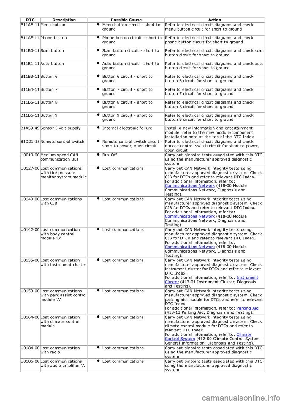
DT CDescriptionPossible CauseAction
B11AE-11Menu butt onMenu but ton ci rcuit - s hort t ogroundRefer to electrical ci rcuit diagrams and checkmenu butt on circui t for s hort t o ground
B11AF-11Phone but t onPhone butt on circui t - s hort togroundRefer to electrical ci rcuit diagrams and checkphone but ton ci rcuit for s hort t o ground
B11B0-11Scan but t onScan butt on circui t - s hort togroundRefer to electrical ci rcuit diagrams and check s canbut t on ci rcuit for short to ground
B11B1-11Auto but t onAut o butt on circui t - s hort togroundRefer to electrical ci rcuit diagrams and check autobut t on ci rcuit for short to ground
B11B3-11Butt on 6But ton 6 circuit - short togroundRefer to electrical ci rcuit diagrams and checkbut t on 6 circui t for s hort t o ground
B11B4-11Butt on 7But ton 7 circuit - short togroundRefer to electrical ci rcuit diagrams and checkbut t on 7 circui t for s hort t o ground
B11B5-11Butt on 8But ton 8 circuit - short togroundRefer to electrical ci rcuit diagrams and checkbut t on 8 circui t for s hort t o ground
B11B6-11Butt on 9But ton 9 circuit - short togroundRefer to electrical ci rcuit diagrams and checkbut t on 9 circui t for s hort t o ground
B1A59-49Sensor 5 volt supplyInternal el ect ronic fail ureIns t al l a new i nformat ion and ent ert ainmentmodule, refer t o t he new modul e/componentins tal lati on note at the t op of the DTC Index
B1D21-15Remote cont rol s wit chRemot e control s wi tch circui t -s hort t o power, open circui tRefer to electrical ci rcuit diagrams and checkremot e cont rol s wi tch circui t for s hort t o power,open ci rcuitU0010-00Medium s peed CANcommunicati on BusBus O ffCarry out pi npoi nt tes ts as s oci ated wit h thi s DTCusi ng t he manufact urer approved diagnost ics ys t em
U0127-00Lost communi cat ionswi th t ire pres s uremonit or s ys t em module
Los t communicat ionsCarry out CAN Network int egrit y t est s us ingmanufacturer approved diagnost ic sys tem. CheckCJB for DTCs and refer to relevant DTC Index.For addit ional informati on, refer t o:Communicati ons Net work (418-00 ModuleCommunicati ons Net work, Di agnos is andTes t ing).
U0140-00Lost communi cat ionswi th CJBLos t communicat ionsCarry out CAN Network int egrit y t est s us ingmanufacturer approved diagnost ic sys tem. CheckCJB for DTCs and refer to relevant DTC Index.For addit ional informati on, refer t o:Communicati ons Net work (418-00 ModuleCommunicati ons Net work, Di agnos is andTes t ing).U0142-00Lost communi cat ionwi th body controlmodule 'B'
Los t communicat ionsCarry out CAN Network int egrit y t est s us ingmanufacturer approved diagnost ic sys tem. CheckCJB for DTCs and refer to relevant DTC Index.For addit ional informati on, refer t o:Communicati ons Net work (418-00 ModuleCommunicati ons Net work, Di agnos is andTes t ing).
U0155-00Lost communi cat ionwi th i nst rument clus t erLos t communicat ionsCarry out CAN Network int egrit y t est s us ingmanufacturer approved diagnost ic sys tem. Checkins trument cl ust er for DTCs and refer to relevantDTC Index.For addit ional informati on, refer t o: Ins trumentClus ter (413-01 Ins t rument Clus t er, Diagnosi sand Tes t ing).
U0159-00Lost communi cat ionswi th park ass i st controlmodule 'A'
Los t communicat ionsCarry out CAN Network int egrit y t est s us ingmanufacturer approved diagnost ic sys tem. Checkparking ai d module for DTCs and refer t o relevantDTC Index.For addit ional informati on, refer t o: Parking Ai d(413-13 Parking Aid, Di agnos is and Tes ti ng).
U0164-00Lost communi cat ionwi th cl imat e cont rolmodule
Los t communicat ionsCarry out CAN Network int egrit y t est s us ingmanufacturer approved diagnost ic sys tem. Checkcl imat e control modul e for DTCs and refer t orel evant DTC Index.For addit ional informati on, refer t o: ClimateCont rol Sys tem (412-00 Cl imat e Control Sys t em -General Informati on, Diagnos is and Tes t ing).
U0184-00Lost communi cat ionwi th radioLos t communicat ionsCarry out pi npoi nt tes ts as s oci ated wit h thi s DTCusi ng t he manufact urer approved diagnost ics ys t emU0186-00Lost communi cat ionswi th audio amplifier 'A'Los t communicat ionsCarry out pi npoi nt tes ts as s oci ated wit h thi s DTCusi ng t he manufact urer approved diagnost ics ys t em
Page 941 of 3229
The wax-t ype thermost at locates i n t he top hos e connecti on t o t he radiat or. A l arge di ameter connecti on at the RH lowers ide connect s the modul e t o t he coolant rail. Two smal l diamet er out lets on the front of t he module provi de t he connect ionfor a supply hos e t o t he heat er mat rix, and a degas l ine t o t he cool ant reservoi r.
The t hermal cont rol module promotes rapi d warming of t he engine t o normal operat ing t emperature by clos ing t he returncool ant connect ion from the engi ne to the radiator. During the engine warmi ng period, t he thermost at is cl os ed and t heby-pas s val ve is open. The by-pass port all ows cool ant t o circul ate t hrough t he closed engi ne circuit vi a t he coolant pump,climate control heat er ci rcuit and EGR cooler.
As t he cool ant t emperat ure i ncreas es , the t hermos t at is opened and the by-pas s valve i s clos ed. The hot cool ant ret urningfrom the engine i s all owed to fl ow from the t hermal cont rol module to the radiator, through the open t hermos tat and t ophose connect ion. Return cool ant from t he radiat or fl ows through the bot tom hos e connect ion t o t he cool ant pump, via thecool ant rail .
The t hermos tat commences opening at 83°C (181°F), and i s ful ly open at 91°C (196°F).
The ECT s ens or is locat ed i n t he thermal control modul e and s ecured in the hous ing wi th a clip. The ECT s ens or provi desan engine coolant temperat ure si gnal t o t he Engi ne Control Module (ECM). The si gnal i s us ed by the ECM to cont rol t heoperati on of the 2 cool ing fans .For addit ional informat ion, refer t o: Electroni c Engi ne Controls - 2.2L Dies el (303-14 El ect ronic Engine Cont rols - 2.2LDies el, Des cript ion and Operat ion).
The ECM al so communi cat es the ECT si gnal on t he high speed Controll er Area Network (CAN) bus t o t he Central Junct ionBox (CJB). The CJB t rans mi ts t he ECT s ignal via t he medium s peed CAN bus to the ins trument cl us t er, for di spl ay on thecool ant t emperat ure gage.For addit ional informat ion, refer t o: Ins t rument Clus ter (413-01 Inst rument Cl us t er, Des cript ion and Operat ion).
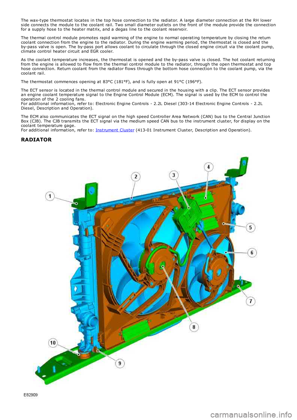
RADIATOR
Page 944 of 3229

CLIMATE CONTROL HEATER MATRIX
The heat er mat rix is i nst all ed in the cli mate cont rol as sembl y, l ocat ed on t he vehi cl e cent er li ne bet ween t he ins trumentpanel and t he engi ne bulkhead. Two pi pes pas s t hrough t he bul khead i nto the engine compart ment and connect to as uppl y and a return cool ing s yst em heat er hos e. The coolant s uppl y hos e is connect ed t o an outl et on the thermal controlmodule. The cool ant return hose is connect ed to the EGR cool er.
The mat ri x is cons truct ed from al uminum wit h t wo end t anks i nterconnect ed wit h t ubes. Aluminum fins are locatedbetween t he t ubes and t rans fer heat to the pas s ing air. Coolant is s upplied to the heater mat ri x at all t imes when theengi ne is running.For addit ional informat ion, refer t o: Heati ng and Vent il ati on (412-01 Cl imat e Control, Des cript ion and Operat ion).
ENGINE COOLANT
The long-l ife engine coolant is s i licate free and is not t o be mixed wi th convent ional engi ne coolant .
The cool ing s ys tem cont ai ns approximat el y 8 l it ers (8.5 US quart s) of a 50/50 wat er and l ong li fe coolant concentrati on.
PRINCIPLES OF OPERATION
Cooling Sys tem Flow at Normal Operat ing Temperat ure
Page 1105 of 3229
Inhi bi tors ’ s ecti on, below.
The batt ery s t atus i nformat ion is t rans mit t ed from t he BMS modul e over t he LIN (l ocal i nt erconnect network) bus t o t heCJB which has a t wo-way communi cat ion wit h the BMS module. The cont rol l ogi c for i nhi bi ti ng engine s hutdown andini ti at ing an early engi ne res tart during a Start/Stop cycl e resi des in t he CJB. The CJB al so act s as t he gateway relayingt hi s informat ion t o t he ECM over the hi gh-s peed CAN bus.
Batt ery s t atus i nformat ion is al so trans mi tt ed from the CJB over the medi um-speed CAN bus t o t he ins t rument clus ter. Theins t rument clus ter dis plays batt ery charge warning mes s ages to indicate generat or or bat tery monit oring sys tem faul ts t ot he driver.
The BMS module cons tant ly computes t he s t at us of the el ect ri cal s ys tem on the bas is of the followi ng data:
batt ery det eriorati onbatt ery s t ate of chargebatt ery current demand.
If any of t hese factors s how a l ow meas urement, t he ECM s us pends t he Stop/Start feature unti l more bat tery power i savai lable. The fact ors are dis cus s ed below:
Batt ery det eriorati on
Alt hough fit t ed wit h a hi gh-performance batt ery bas ed on AGM (abs orpti on glas s mat ) technol ogy, t he charge holdingcapacit y of the bat tery wi ll s ti ll deteriorat e, however at a much s lower rat e t han a conventi onal bat tery. This degradat ionwil l reflect on the amount of charge t he bat t ery can hold unt il it reduces t o a condit ion where the bat tery wi ll needrepl acing.
The batt ery moni toring s yst em cal culat es t he condit ion of t he batt ery by obs erving a range of i nput s including:
ambient t emperaturecharge and dis charge act ivi tyvolt age andint ernal res is t ance.
The lat est condit ion value of t he batt ery i s s tored in the dedicated memory of t he BMS t o ens ure t he mos t accurat eforecas t of the bat teries condi ti on.
Stat e of charge
The BMS analys es how much charge has been drawn or repl enis hed to det ermi ne t he bat tery’s pres ent s tat e of charge.
Current demand
Duri ng a St op/Start cycle when vehicl e s ys t em us e i s in hi gh demand, for exampl e t he fol lowing are operat ing:
head li ght sclimate controlaudi o s yst em.
The batt ery wi ll dis charge more rapi dly due t o t he high current demand.
In thi s event t he BMS calculat es various fact ors t o determine how long t he batt ery can s upply a current at the presentlevel of demand. This calculat ion i s used by the CJB t o determine if t o authori ze whichever i s needed i n t he Stop/St artcycle, ei ther to:
prevent an engi ne s top, orini ti at e an engine res tart.
To provide this informati on t o t he CJB the BMS modul e calculates a range of batt ery variables , including:
s tat e of chargebatt ery s urface temperat ure to cal culat e t he int ernal temperat ureint ernal res is t ancevolt agecurrent flow into and from t he batt ery.
The batt ery moni toring s yst em cal culat es t hes e vari abl es agai nst programmed det ailed bat tery li fe model s t o determinehow l ong the gi ven current can be s upport ed.
Batt ery moni toring s ys tem modes
The batt ery moni toring s yst em has three di s ti nct modes :
Acti ve mode: during normal vehicle operat ion, batt ery dat a i s upl oaded and calculat ed every s econd.Sleep mode: duri ng ignit ion off, bat tery dat a i s uploaded every s econd and calculated every hour t o reduce i nacti vecurrent drai n.Trans port mode: bat t ery moni tori ng int ervals are mi nimi zed.
Batt ery replacement
If a new batt ery is fit ted t o t he vehicle, the BMS (bat tery monit ori ng s ys t em) module wi ll requi re recal ibrat ing t o regi s tert he greater charge holding capaci ty of the bat tery, t his i s performed us ing Land Rover approved di agnos ti c equi pment. If adiagnost ic s ys tem is not avail abl e t he BMS module will recal ibrat e automat icall y however, this could take 48 hours tocomplete depending on vehicle usage. The Stop/St art s ys tem wil l not funct ion correctly unt il t he BMS module isrecali brated.
If the BMS modul e i s replaced t he module wi ll re-calibrate aut omati cal ly.
Page 1108 of 3229
however remain i ll uminated.
A ‘st all recovery’ event is the onl y s tat e when t he Stop/St art s yst em wil l permit t he engine t o be s t art ed when thet ransmis s ion i s in gear; hence t he requirement for t he cl utch pedal to be full y depres sed. If the s t all recovery fai ls and t heengi ne does not res tart, t he dri ver wi ll be reques ted vi a t he Mess age Center t o ‘s elect neutral ’ to at t empt anot her rest art .
If the engine does not res t art aft er thi s request t he ‘st all recovery’ mode wil l ti me-out and deact ivate. At t his point t he‘Eco’ i con in t he i ns t rument panel wi ll exti ngui sh and the light s usual ly as s ociat ed wi th an engi ne st all wi ll il lumi nat e. As ares ult t he dri ver will be requi red to perform a convent ional engi ne res tart.
Alt hough st all recovery i s a feat ure of t he St op/Start sys t em i t is pos si ble for it t o acti vat e i ndependent ly from t heStop/St art parameters . For exampl e:
If the St op/Start s ys t em has been deact ivated by the driver st all recovery wi ll s ti ll funct ion.Stal l recovery wil l act ivate at ambi ent temperat ures as l ow as (minus ) - 2°C, whereas the St op/Syst em operat ingt emperature threshold is above 4°C.Different t o t he operat ion of t he Stop/St art s yst em, s tal l recovery wil l st il l functi on when the vehicle is t owing;refer to the ‘Trail er Towi ng’ s ect ion.
• NOTE: As t he neces s ary cri teria will not have been sat is fi ed when t he vehi cl e i s at the beginning of a journey s t allrecovery wi ll not functi on. For exampl e, if t he vehi cl e s tal ls when l eavi ng the garage or driveway a convent ional engineres t art wi ll be required.
Trailer Towing
The Stop/St art s ys tem wil l aut omati cal ly di sabl e when t rail er light s are det ect ed by t he CJB via s ignals from t he t rail ermodule, t hi s informat ion i s t hen trans mi tt ed t o t he ECM. It i s not pos s ibl e for t he s ys t em t o det ect when a trai ler powerplug i s ins ert ed i n the vehicl e’s t owi ng s ocket s o it us es operat ion of t he trail er l ights as it s indi cat or.
The t rail er towing sys tem inhi bi ts St op/St art as i t is pos s ible that trail er power requirements could interfere wit h t heoperati on of the bat tery monit ori ng s ys t em. In parti cul ar, a t rai ler batt ery could revers e t he feed current t o t he vehicleduri ng an engi ne cranking event , t hi s coul d pos si bly:
Confus e t he bat t ery monit ori ng s ys t em i nto det ect ing an unreal is t ically smal l current at engi ne cranking.Rupture the fus e as sociat ed wit h t he t rail er modul e.
Climate Control System
• NOTE: The ‘ECON’ butt on has been renamed ‘A/C’ to prevent confus ion wi th the St op/St art s yst em ‘Eco’ s wit ch.
A number of changes have been made to the l ogi c and operati on of climat e control system, wit hi n a St op/St art cycle to:
maint ain occupant comfortprevent winds hi eld mis ti ngcons erve bat tery power.
This has been achi eved by the ATC (automat ic t emperat ure control) module monit oring and varyi ng, as necess ary variousclimate control funct ions wi thi n a St op/Start cycle.
In s ome circums t ances t he ATC has t he capabil it y to inhibit an engi ne s hut down or init iat e an engine rest art wit hi n aStop/St art cycle. Thi s i s achi eved by t he ATC module communi cat ing wit h t he CJB on the medi um s peed CAN. The variousoverri de functi ons the ATC has in a St op/St art cycl e are di s cus s ed bel ow:
Coolant temperat ure
The ATC module wil l i nhibit an engine shut down or i nit iat e an engine res t art wi thi n a St op/Start cycle if t he coolantt emperature fal ls below the calculat ed t hreshol d to s upport t he cabin t emperat ure s et by t he vehi cl e occupant s .
W i nds hiel d demis t ing
The variant of cli mate control fi tt ed t o the vehicl e influences t he s oft ware changes that have been made. For exampl e, thebase cl imat e-control s ys tem does not have a humi dit y s ens or, as us ed on a highline sys tem t o ini ti at e a winds hi elddemis t . Therefore, a calculat ion for demis ti ng the winds hi eld i s made us ing t he s ignals from t he rai n s ens or and ambientt emperature s ens or. Us i ng the probabi lit y t hat windshi eld mis ti ng wil l occur if i t is raining and t he ambi ent t emperat ure i scool , the ATC wil l presume a wi nds hiel d demis t is required and s tart the engine when i n a St op/St art cycl e.
Evaporat or temperat ure the main cause of windshi eld mis ti ng is al s o monit ored and t he high-line cl imat e cont rol s yst emwil l periodicall y cool t he evaporat or as neces s ary t o reduce mi s ti ng during a Stop/St art cycl e. The sys tem operates thewinds hield demis t s hut ter and i f the evaporator i s wet t he shut ter wi ll remai n clos ed for a few seconds after an engineres t art unti l the vapor is di ss ipat ed.
If the driver sel ect s eit her ‘programmed defros t ’ or t he ‘wi ndshi el d heater’ i t is as s umed t hat a qui ck demis t of thewinds hield is requi red. Therefore, t he ATC vi a the CJB will ei ther: i nhibit an engine shut down or i nit iat e an engine res t art .
Heater fan speed
Duri ng an engine s hutdown t he ATC monit ors cabin temperat ure and maint ai ns the fan speed at a l evel that wi ll cons erve,for as l ong as poss ibl e t he heat i n t he core of t he cabi n heat er. If the driver s elect s a hi gher fan s peed and the heatcannot be mai ntained i n t he heat er core, the engine will rest art .
Heated rear window and heated s eats
If the heated rear window or heated s eats are acti ve or act ivated during an engine shut down event t he power out put oft he relevant s ys t em wi ll be i nt errupted unt il the engi ne is rest art ed. The tell -t ale light i n t he relevant s wit ch wil lil lumi nat e t o i ndi cat e t he s ys t em i s act ive even t hough the s ys tem is recei vi ng no power. This feature is us ed t o conservebatt ery power.
Page 1218 of 3229
The posi ti on of the inlet cams haft is det ermi ned by the ECM us ing s ignals from t he CKP s ens or and t he CMP s ens ors. TheECM can t hen use the VCT sol enoid val ve to cont rol t he angl e of the cams haft by controlli ng t he fl ow of oil t o t he VCT unit .
The camshaft is s ecured t o t he rot or in t he VCT unit . Oil pres s ure suppli ed to eit her s ide of t he VCT unit from t he VCTs olenoi d valve can rot ate the rotor and hence the cams haft i n eit her di recti on. The VCT sol enoi d is operat ed by t he ECMus ing PW M, hi gh frequency s wit chi ng which provi des rapid and preci se cont rol of the i nlet cams haft pos i ti on. The i nletcamshaft pos i ti on can be adjust ed wi thi n 40 degrees of cranks haft rotat ion.
Camshaft Profile Switching (CPS) Control
The inl et cams haft has , in addit ion to t he VCT control, a CPS funct ion whi ch is al so cont roll ed by t he ECM. The CPS cont rolcan vary t he val ve li ft height and durat ion of t he camshaft lobes by adjus ti ng the area of t he hydraul ic t appet whi ch act son one of t wo cam l obe profi les . The CPS cont rol is vi a t wo CPS s olenoid valves , located at each end of the i nlet cams haft.The CPS s olenoid valves cont rol t he posi ti on of hydraul ic t appet as s embli es which can be s et in one of t wo pos it ions; lowand high.
Two CPS s olenoids are us ed so that t he hydraul ic t appet s can be adjus t ed when no load i s applied, for example the camlobes are off t he hydraul ic t appet s and t he cam bas e circl e is act ing on t he t appet , thi s keeps t he s tress on components toa minimum. One CPS s ol enoi d s uppl ies oi l press ure to the hydrauli c t appet s of cyli nders 1, 2 and 4 and the s econd CPSs olenoi d s uppl ies oi l press ure to the tappet s of cylinders 3, 5 and 6.
At engi ne s tart and at low engine oi l temperat ures (below 40°C (104°F)) the ECM does not direct engine oi l pres sure t ot he hydraul ic t appet s and t herefore the hydraul ic t appet s are in t heir s pring loaded, l ow posi ti on.For addit ional informat ion, refer t o: Engi ne - 3.2L (303-01, Descripti on and Operat ion).
Ignition Control
The ECM calculat es the opt imum ignit ion ti ming bas ed on pre-programmed maps and informat ion from t he foll owings ens ors :
CKP s ensorCMP s ensorsMAF s ensorECT s ens orElectric t hrot tl e TP s ensorKnock s ens orsTCMIgni ti on coi ls .
Duri ng engi ne s tarti ng the ECM uses a fi xed ignit ion s et ti ng. W hen the engine has s tart ed and the vehicle is bei ng driven,t he ECM adjus ts the i gni ti on t imi ng accordi ngl y us ing ot her paramet ers s uch as engine s peed, l oad and temperat ure.
Once the engi ne has reached i ts normal operati ng temperature, t he ECM moni tors the si gnal s from the knock sens ors . Ifany of the cyli nders produce knocking, the i gnit ion t imi ng for t hat cyli nder wi ll be retarded unt il t he knocking has s t opped.The ignit ion is t hen gradually advanced back t o t he normal t imi ng or unt il t he knocking re-occurs .
The ECM us es informat ion from the TCM t o provide t orque l imi tat ion during t rans mis s ion s hifts . The i gni ti on ti mi ng isadjus ted t o moment ari ly reduce t he engine t orque output t o give a smoot h t rans mis s ion shi ft and reduce l oad on thet ransmis s ion.
Air Conditioning (A/C) Compressor Control
The ECM controls t he operati on of the A/C compres s or and reacts t o reques ts from t he ATC module vi a t he high s peed CANbus. The compres s or is a variable di s pl acement unit and t he ECM controls , via a sol enoi d, t he dis placement of thecompres sor t o adjus t load during cert ain driving condit ions.
Duri ng engi ne s tart-up, movi ng from a s tandst il l and under hard accelerat ion, the ECM s et s t he mi nimum dis placement oft he compress or t o reduce the effect on t he engi ne t orque output. The ECM uses i nformati on from t he ATC module, t he A/Cpres s ure s ensor, the el ect ri c t hrott le TP s ens or and the ECT sens or to det ermi ne compres sor control . The ATC modulet ransmit s climate control and driver reques ts t o t he ECM and t he ECM det ermi nes the priori ty of thes e request s overengi ne performance.
Page 1628 of 3229
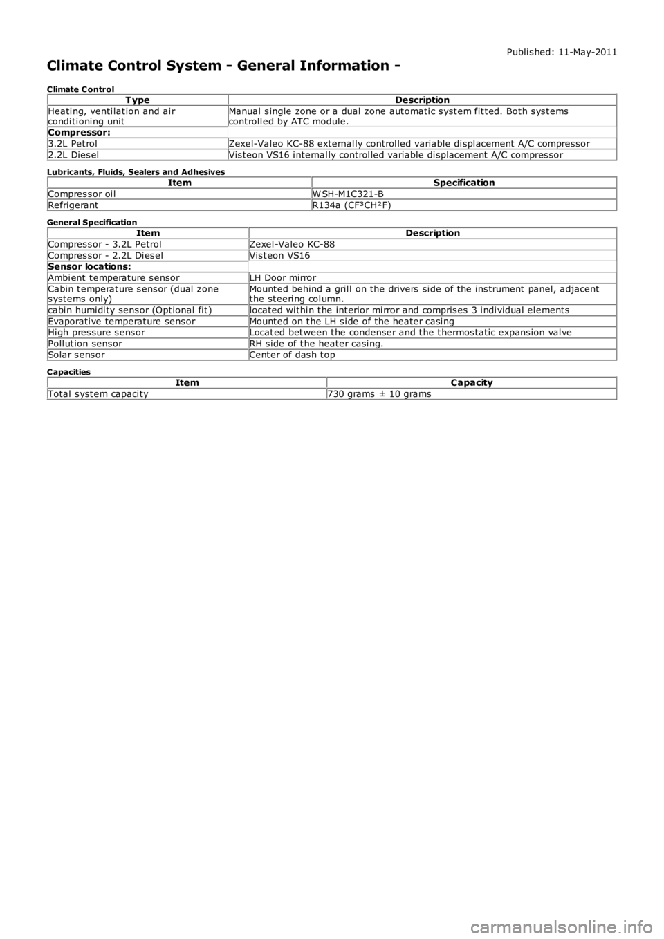
Publi s hed: 11-May-2011
Climate Control System - General Information -
C limate C ontrolT ypeDescription
Heati ng, venti lat ion and ai rcondi ti oni ng unitManual s ingle zone or a dual zone aut omati c s yst em fit t ed. Bot h s ys t emscont roll ed by ATC module.Compressor:
3.2L Pet rolZexel-Valeo KC-88 external ly control led variable di spl acement A/C compres sor
2.2L Dies elVis teon VS16 i nternal ly control led variable di spl acement A/C compres sor
Lubricants, Fluids, Sealers and AdhesivesItemSpecification
Compres s or oi lW SH-M1C321-B
RefrigerantR134a (CF³CH²F)
General SpecificationItemDescription
Compres s or - 3.2L PetrolZexel -Valeo KC-88
Compres s or - 2.2L Di es elVis t eon VS16Sensor locations:
Ambi ent t emperat ure s ensorLH Door mirror
Cabin t emperat ure s ens or (dual zones yst ems only)Mount ed behind a gril l on the drivers si de of the ins trument panel, adjacentthe st eeri ng col umn.
cabi n humi di ty sens or (Opt ional fit )located wi thi n t he int erior mi rror and compris es 3 i ndi vidual el ement s
Evaporati ve temperat ure sens orMount ed on t he LH s i de of the heater casi ngHi gh pres sure s ens orLocat ed bet ween t he condenser and t he t hermos tat ic expans ion val ve
Poll ut ion sens orRH s ide of t he heater casi ng.
Solar s ens orCent er of das h t op
C apacitiesItemCapacity
Total s yst em capaci ty730 grams ± 10 grams
Page 1629 of 3229
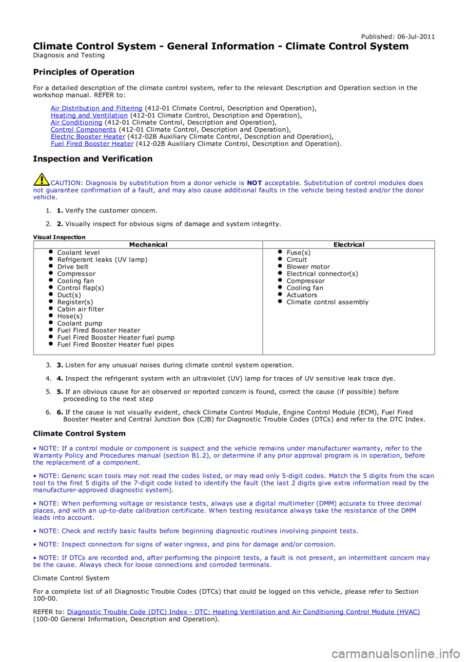
Publi shed: 06-Jul-2011
Climate Control System - General Information - Climate Control System
Diagnosi s and Tes ti ng
Principles of Operation
For a detail ed descripti on of the cl imat e cont rol s yst em, refer to the relevant Des cri pti on and Operati on s ect ion i n t heworks hop manual . REFER to:
Air Dis t ri but ion and Fi lt ering (412-01 Cl imat e Control, Des cript ion and Operat ion),Heat ing and Vent il at ion (412-01 Cl imat e Control, Des cript ion and Operat ion),Air Condi ti oning (412-01 Cli mate Cont rol , Des cri pti on and Operati on),Cont rol Component s (412-01 Cli mate Cont rol , Des cri pti on and Operati on),Elect ric Boost er Heater (412-02B Auxi liary Cli mate Cont rol , Descri pti on and Operat ion),Fuel Fired Boos t er Heat er (412-02B Auxil iary Cli mate Cont rol, Des cri pt ion and Operati on).
Inspection and Verification
CAUTION: Di agnos is by s ubs ti tut ion from a donor vehicle is NO T acceptabl e. Subs ti tut ion of cont rol modules doesnot guarant ee confirmat ion of a faul t, and may als o caus e addit ional fault s i n t he vehi cl e being t est ed and/or t he donorvehi cl e.
1. Verify t he cus t omer concern.1.
2. Vis ually ins pect for obvious s igns of damage and s ys t em i ntegri ty.2.
Visual InspectionMechanicalElectrical
Coolant levelRefrigerant l eaks (UV l amp)Drive beltCompres s orCooli ng fanControl flap(s)Duct(s )Regis ter(s )Cabin ai r fi lt erHos e(s )Coolant pumpFuel Fi red Boos ter HeaterFuel Fi red Boos ter Heater fuel pumpFuel Fi red Boos ter Heater fuel pipes
Fus e(s)Circui tBlower mot orElectrical connect or(s)Compres s orCool ing fanAct uatorsCli mate cont rol ass embly
3. Lis ten for any unus ual noi ses during cli mate cont rol s ys t em operat ion.3.
4. Ins pect t he refri gerant s ys t em wi th an ult raviolet (UV) lamp for t races of UV s ens i ti ve leak t race dye.4.
5. If an obvious cause for an obs erved or report ed concern is found, correct t he caus e (if pos s ible) beforeproceeding t o t he next s t ep5.
6. If t he caus e is not vis ually evi dent , check Cli mate Cont rol Module, Engi ne Control Module (ECM), Fuel FiredBoos ter Heater and Central Juncti on Box (CJB) for Di agnos ti c Trouble Codes (DTCs ) and refer to the DTC Index.6.
Climate Control System
• NOTE: If a cont rol module or component i s s uspect and the vehicl e remai ns under manufacturer warrant y, refer t o t heW arranty Pol icy and Procedures manual (s ect ion B1.2), or determine i f any pri or approval program is i n operat ion, beforet he replacement of a component.
• NOTE: Generic scan t ool s may not read the codes li st ed, or may read only 5-digi t codes . Match t he 5 digi ts from t he s cant ool t o t he fi rs t 5 di gi ts of the 7-digit code li s ted t o i dent ify the fault (the last 2 digi ts gi ve ext ra informati on read by themanufacturer-approved di agnos ti c s ys t em).
• NOTE: W hen performing volt age or res is t ance t est s , always use a digi tal mult imeter (DMM) accurat e t o t hree deci malplaces, and wi th an up-t o-date cal ibrat ion cert ificate. W hen tes ti ng res is t ance al ways take t he res is t ance of t he DMMleads i nt o account .
• NOTE: Check and recti fy bas ic faul ts before beginni ng diagnos t ic rout ines i nvol vi ng pinpoint t es t s.
• NOTE: Ins pect connect ors for s igns of water ingres s , and pins for damage and/or corros ion.
• NOTE: If DTCs are recorded and, aft er performi ng the pi npoi nt tes ts , a fault is not present , an int ermi tt ent concern maybe t he caus e. Always check for loose connect ions and corroded terminals .
Cli mate Cont rol Syst em
For a compl ete lis t of all Di agnos ti c Trouble Codes (DTCs) t hat could be logged on this vehicle, pleas e refer to Sect ion100-00.
REFER to: Di agnos ti c Trouble Code (DTC) Index - DTC: Heati ng Vent il ati on and Air Condit ioning Control Modul e (HVAC)(100-00 General Informati on, Des cri pti on and Operati on).
Page 1630 of 3229
Publi s hed: 11-May-2011
Climate Control System - General Information - Air Conditioning (A/C)
System Recovery, Evacuation and Charging
General Procedures
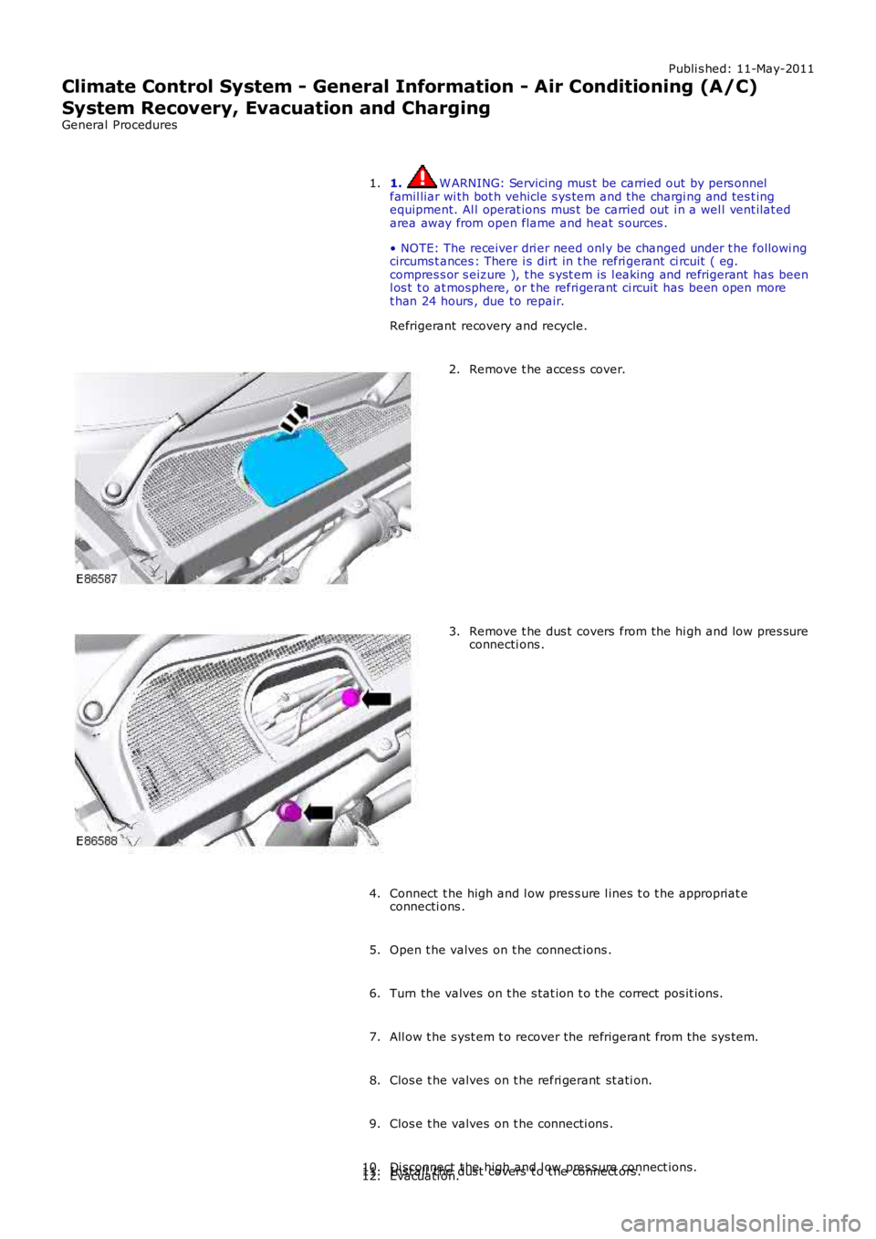
1. W ARNING: Servicing mus t be carried out by pers onnelfamil liar wi th bot h vehicle s ys tem and the chargi ng and tes t ingequipment. Al l operat ions mus t be carried out i n a wel l vent ilat edarea away from open flame and heat s ources .
• NOTE: The receiver dri er need onl y be changed under t he followi ngcircums t ances : There i s dirt in t he refri gerant ci rcuit ( eg.compres s or s eizure ), t he s yst em is l eaking and refrigerant has beenl os t t o at mosphere, or t he refri gerant ci rcuit has been open moret han 24 hours , due to repair.
Refrigerant recovery and recycle.
1.
Remove t he acces s cover.2.
Remove t he dus t covers from the hi gh and low pres sureconnecti ons .3.
Connect t he high and l ow pres s ure l ines t o t he appropriat econnecti ons .4.
Open t he valves on t he connect ions .5.
Turn the valves on t he s tat ion t o t he correct pos it ions.6.
All ow t he s yst em t o recover the refrigerant from the sys tem.7.
Clos e t he valves on t he refri gerant st ati on.8.
Clos e t he valves on t he connecti ons .9.
Di sconnect t he high and l ow pres s ure connect ions.10.Inst all t he dus t covers t o t he connect ors .11.Evacuati on.12.