fuse chart LAND ROVER FRELANDER 2 2006 Repair Manual
[x] Cancel search | Manufacturer: LAND ROVER, Model Year: 2006, Model line: FRELANDER 2, Model: LAND ROVER FRELANDER 2 2006Pages: 3229, PDF Size: 78.5 MB
Page 913 of 3229
Publi s hed: 11-May-2011
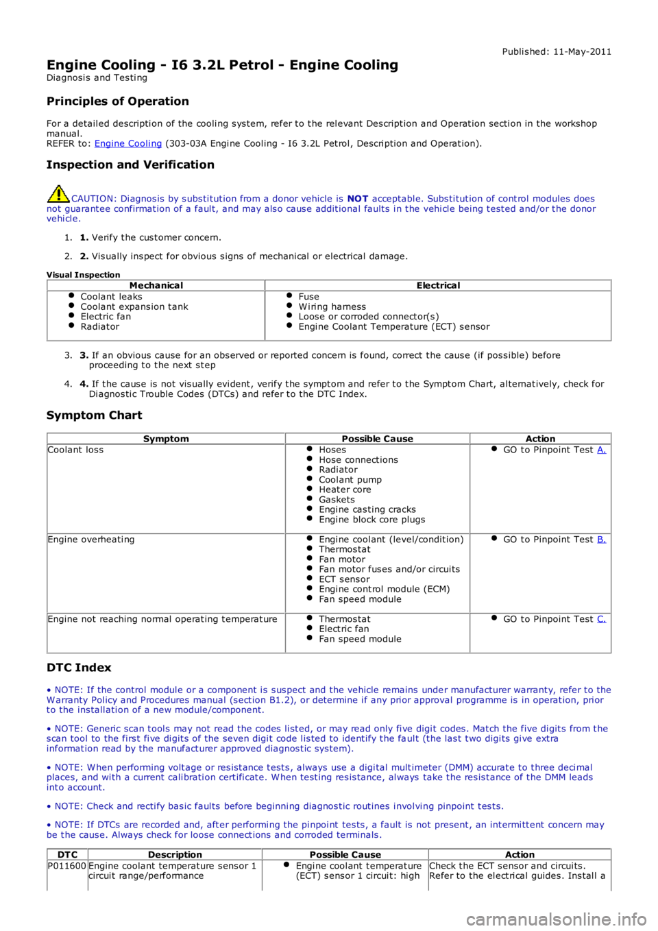
Engine Cooling - I6 3.2L Petrol - Engine Cooling
Diagnosi s and Tes ti ng
Principles of Operation
For a detail ed descripti on of the cooli ng s ys t em, refer t o t he rel evant Des cript ion and Operat ion secti on in the workshopmanual.REFER to: Engine Cooli ng (303-03A Engi ne Cool ing - I6 3.2L Pet rol , Descri pti on and Operat ion).
Inspection and Verification
CAUTION: Di agnos is by s ubs ti tut ion from a donor vehicle is NO T acceptabl e. Subs ti tut ion of cont rol modules doesnot guarant ee confirmat ion of a faul t, and may als o caus e addit ional fault s i n t he vehi cl e being t est ed and/or t he donorvehi cl e.
1. Verify t he cus t omer concern.1.
2. Vis ually ins pect for obvious s igns of mechani cal or electrical damage.2.
Visual InspectionMechanicalElectrical
Coolant leaksCoolant expans ion t ankElectric fanRadiat or
FuseW i ri ng harnessLoos e or corroded connect or(s )Engi ne Coolant Temperature (ECT) s ensor
3. If an obvious cause for an obs erved or report ed concern is found, correct t he caus e (if pos s ible) beforeproceeding t o t he next s t ep3.
4. If t he caus e is not vis ually evi dent , verify t he sympt om and refer t o t he Sympt om Chart, al ternat ively, check forDi agnos ti c Trouble Codes (DTCs) and refer t o t he DTC Index.4.
Symptom Chart
SymptomPossible CauseActionCoolant los sHosesHose connect ionsRadi atorCool ant pumpHeat er coreGasketsEngi ne cas t ing cracksEngi ne block core plugs
GO t o Pinpoint Test A.
Engine overheati ngEngi ne cool ant (level/condit ion)Thermos tatFan motorFan motor fus es and/or circui tsECT s ens orEngi ne cont rol module (ECM)Fan speed module
GO t o Pinpoint Test B.
Engine not reaching normal operat ing t emperat ureThermos tatElect ric fanFan speed module
GO t o Pinpoint Test C.
DTC Index
• NOTE: If the control modul e or a component i s s us pect and the vehicle remains under manufacturer warrant y, refer t o theW arranty Pol icy and Procedures manual (s ect ion B1.2), or determine i f any pri or approval programme is in operat ion, pri ort o the ins tall ati on of a new module/component.
• NOTE: Generic scan t ool s may not read the codes li st ed, or may read only fi ve digit codes . Mat ch the five di git s from t hes can tool to the firs t fi ve di git s of the seven digi t code l is ted to ident ify t he faul t (t he las t t wo digi ts gi ve ext rainformat ion read by the manufact urer approved diagnos t ic s ys tem).
• NOTE: W hen performing volt age or res is t ance t est s , always use a digi tal mult imeter (DMM) accurat e t o t hree deci malplaces, and wi th a current cali brati on cert ifi cat e. W hen t est ing res is tance, al ways take t he res is t ance of t he DMM leadsint o account.
• NOTE: Check and recti fy bas ic faul ts before beginni ng diagnos t ic rout ines i nvol vi ng pinpoint t es t s.
• NOTE: If DTCs are recorded and, aft er performi ng the pi npoi nt tes ts , a fault is not present , an int ermi tt ent concern maybe t he caus e. Always check for loose connect ions and corroded terminals .
DT CDescriptionPossible CauseAction
P011600Engine coolant temperature s ens or 1circui t range/performanceEngi ne cool ant t emperat ure(ECT) s ens or 1 circui t: hi ghCheck t he ECT s ensor and circui ts .Refer to the el ect ri cal guides . Ins tal l a
Page 947 of 3229
Publi s hed: 11-May-2011
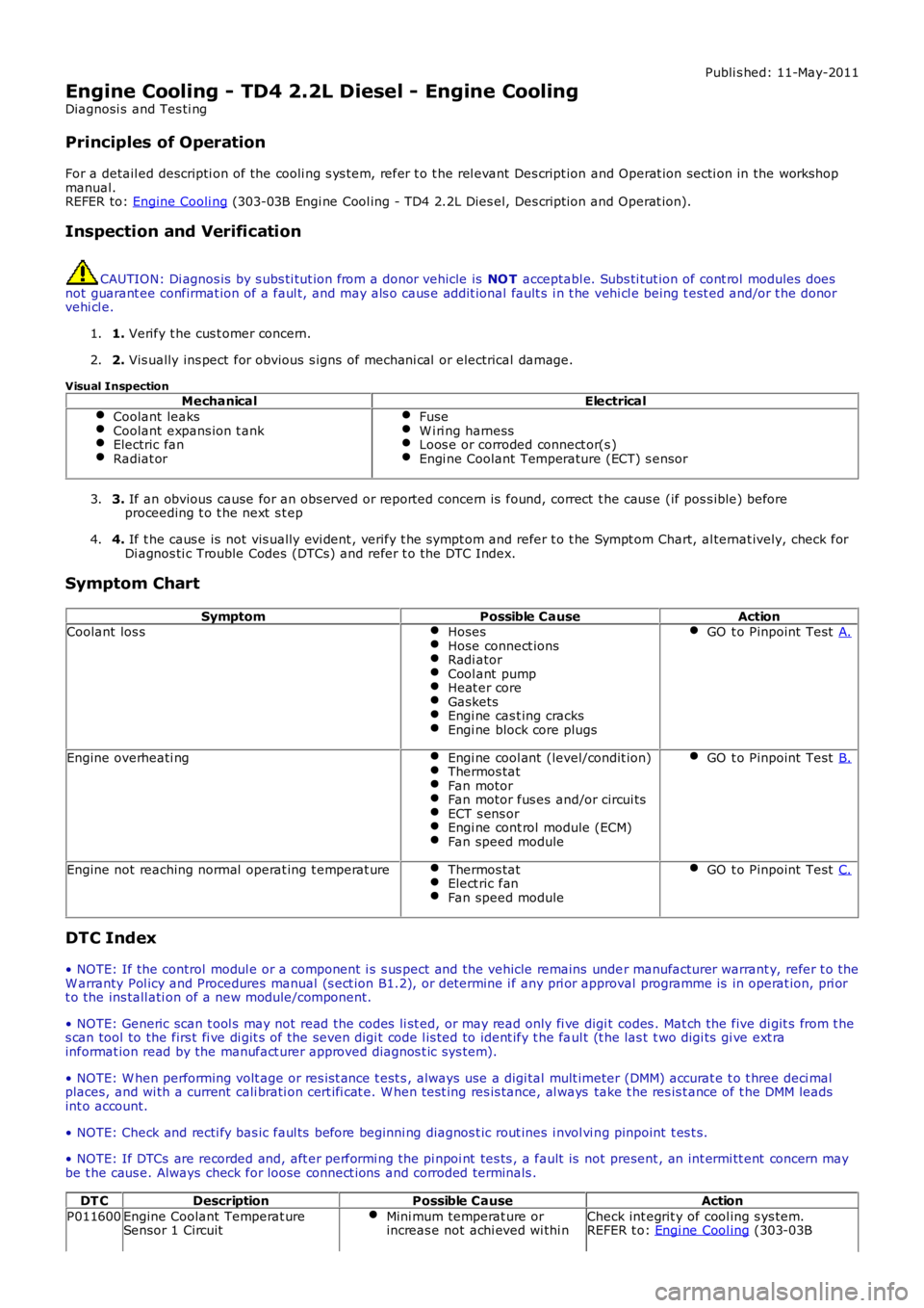
Engine Cooling - TD4 2.2L Diesel - Engine Cooling
Diagnosi s and Tes ti ng
Principles of Operation
For a detail ed descripti on of the cooli ng s ys t em, refer t o t he rel evant Des cript ion and Operat ion secti on in the workshop
manual.
REFER to: Engine Cooli ng (303-03B Engi ne Cool ing - TD4 2.2L Dies el, Des cript ion and Operat ion).
Inspection and Verification CAUTION: Di agnos is by s ubs ti tut ion from a donor vehicle is
NO T acceptabl e. Subs ti tut ion of cont rol modules does
not guarant ee confirmat ion of a faul t, and may als o caus e addit ional fault s i n t he v ehi cl e being t est ed and/or t he donor
vehi cl e.
1. Verify t he cus t omer concern.
1.
2. Vis ually ins pect for obvious s igns of mechani cal or electrical damage.
2.
Visual Inspection Mechanical Electrical
Coolant leaks Coolant expans ion t ank
Electric fan
Radiat or Fuse
W i ri ng harness
Loos e or corroded connect or(s )
Engi ne Coolant Temperature (ECT) s ensor
3.
If an obvious cause for an obs erved or report ed concern is found, correct t he caus e (if pos s ible) before
proceeding t o t he next s t ep
3.
4. If t he caus e is not vis ually evi dent , verify t he sympt om and refer t o t he Sympt om Ch art, al ternat ively, check for
Di agnos ti c Trouble Codes (DTCs) and refer t o t he DTC Index.
4.
Symptom Chart Symptom Possible CauseAction
Coolant los s Hoses Hose connect ions
Radi ator
Cool ant pump
Heat er core
Gaskets
Engi ne cas t ing cracks
Engi ne block core plugs GO t o Pinpoint Test
A.Engine overheati ng
Engi ne cool ant (level/condit ion) Thermos tat
Fan motor
Fan motor fus es and/or circui ts
ECT s ens or
Engi ne cont rol module (ECM)
Fan speed module GO t o Pinpoint Test
B.Engine not reaching normal operat ing t emperat ure
Thermos tat Elect ric fan
Fan speed module GO t o Pinpoint Test
C.DTC Index
• NOTE: If the control modul e or a component i s s us pect and the vehicle remains unde r manufacturer warrant y, refer t o the
W arranty Pol icy and Procedures manual (s ect ion B1.2), or determine i f any pri or appr oval programme is in operat ion, pri or
t o the ins tall ati on of a new module/component.
• NOTE: Generic scan t ool s may not read the codes li st ed, or may read only fi ve digi t codes . Mat ch the five di git s from t he
s can tool to the firs t fi ve di git s of the seven digi t code l is ted to ident ify t he fa ul t (t he las t t wo digi ts gi ve ext ra
informat ion read by the manufact urer approved diagnos t ic s ys tem).
• NOTE: W hen performing volt age or res is t ance t est s , always use a digi tal mult imeter (DMM) accurat e t o t hree deci mal
places, and wi th a current cali brati on cert ifi cat e. W hen t est ing res is tance, al ways take t he res is t ance of t he DMM leads
int o account.
• NOTE: Check and recti fy bas ic faul ts before beginni ng diagnos t ic rout ines i nvol vi n g pinpoint t es t s.
• NOTE: If DTCs are recorded and, aft er performi ng the pi npoi nt tes ts , a fault is no t present , an int ermi tt ent concern may
be t he caus e. Always check for loose connect ions and corroded terminals .
DT C Description Possible Cause Action
P011600 Engine Coolant Temperat ure
Sensor 1 Circuit Mini mum temperat ure or
increas e not achi eved wi thi n Check int egrit y of cool ing s ys tem.
REFER t o: Engi ne Cool ing (303-03B
Page 978 of 3229
Publi s hed: 11-May-2011
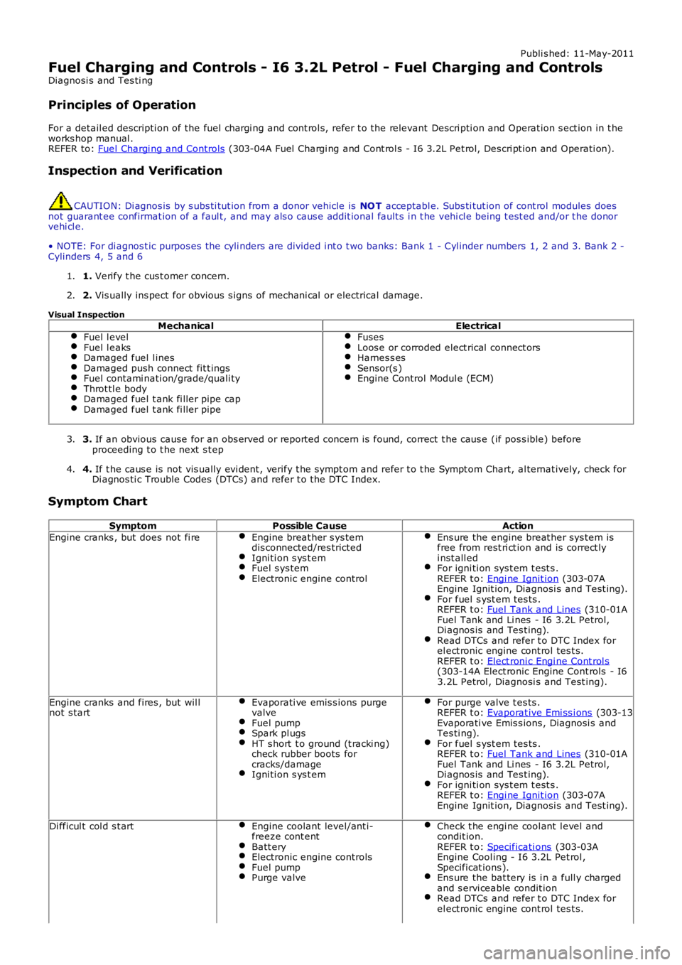
Fuel Charging and Controls - I6 3.2L Petrol - Fuel Charging and Controls
Diagnosi s and Tes ti ng
Principles of Operation
For a detail ed descripti on of the fuel chargi ng and cont rol s, refer t o the relevant Descri pti on and Operat ion s ect ion in t heworks hop manual .REFER to: Fuel Chargi ng and Controls (303-04A Fuel Chargi ng and Cont rol s - I6 3.2L Pet rol, Des cri pt ion and Operati on).
Inspection and Verification
CAUTION: Di agnos is by s ubs ti tut ion from a donor vehicle is NO T acceptabl e. Subs ti tut ion of cont rol modules doesnot guarant ee confirmat ion of a faul t, and may als o caus e addit ional fault s i n t he vehi cl e being t est ed and/or t he donorvehi cl e.
• NOTE: For di agnos t ic purpos es the cyli nders are divided i nt o t wo banks: Bank 1 - Cyl inder numbers 1, 2 and 3. Bank 2 -Cylinders 4, 5 and 6
1. Verify t he cus t omer concern.1.
2. Vis ually ins pect for obvious s igns of mechani cal or electrical damage.2.
Visual Inspection
MechanicalElectricalFuel l evelFuel l eaksDamaged fuel l inesDamaged push connect fit t ingsFuel contami nati on/grade/quali tyThrot tl e bodyDamaged fuel t ank fi ller pipe capDamaged fuel t ank fi ller pipe
FusesLoos e or corroded elect rical connect orsHarnes s esSensor(s )Engine Control Modul e (ECM)
3. If an obvious cause for an obs erved or report ed concern is found, correct t he caus e (if pos s ible) beforeproceeding t o t he next s t ep3.
4. If t he caus e is not vis ually evi dent , verify t he sympt om and refer t o t he Sympt om Chart, al ternat ively, check forDi agnos ti c Trouble Codes (DTCs) and refer t o t he DTC Index.4.
Symptom Chart
SymptomPossible CauseAction
Engine cranks , but does not fi reEngine breat her s ys temdis connected/res trictedIgni ti on s ys t emFuel s ys temElectronic engine control
Ens ure the engine breat her sys tem isfree from rest ri ct ion and is correct lyi nst all edFor igni ti on sys t em t est s .REFER t o: Engi ne Ignit ion (303-07AEngine Ignit ion, Diagnosi s and Test ing).For fuel s yst em tes ts .REFER t o: Fuel Tank and Lines (310-01AFuel Tank and Li nes - I6 3.2L Petrol,Di agnos is and Tes t ing).Read DTCs and refer t o DTC Index forel ect ronic engine cont rol tes t s.REFER t o: Elect roni c Engi ne Cont rol s(303-14A Elect ronic Engine Cont rols - I63.2L Petrol , Diagnosi s and Test ing).
Engine cranks and fires , but wil lnot s tartEvaporati ve emis s ions purgevalveFuel pumpSpark pl ugsHT s hort t o ground (t racki ng)check rubber boots forcracks/damageIgni ti on s ys t em
For purge valve t es ts .REFER t o: Evaporat ive Emi ss i ons (303-13Evaporati ve Emis s ions , Diagnosi s andTes ti ng).For fuel s yst em tes ts .REFER t o: Fuel Tank and Lines (310-01AFuel Tank and Li nes - I6 3.2L Petrol,Di agnos is and Tes t ing).For igni ti on sys t em t est s .REFER t o: Engi ne Ignit ion (303-07AEngine Ignit ion, Diagnosi s and Test ing).
Di fficul t col d s t artEngine coolant level/ant i-freeze cont entBatt eryElectronic engine controlsFuel pumpPurge valve
Check t he engi ne cool ant l evel andcondit ion.REFER t o: Specificati ons (303-03AEngine Cool ing - I6 3.2L Pet rol ,Specificat ions ).Ens ure the bat tery is i n a full y chargedand s ervi ceable condit ionRead DTCs and refer t o DTC Index forel ect ronic engine cont rol tes t s.
Page 1124 of 3229
Publi s hed: 11-May-2011
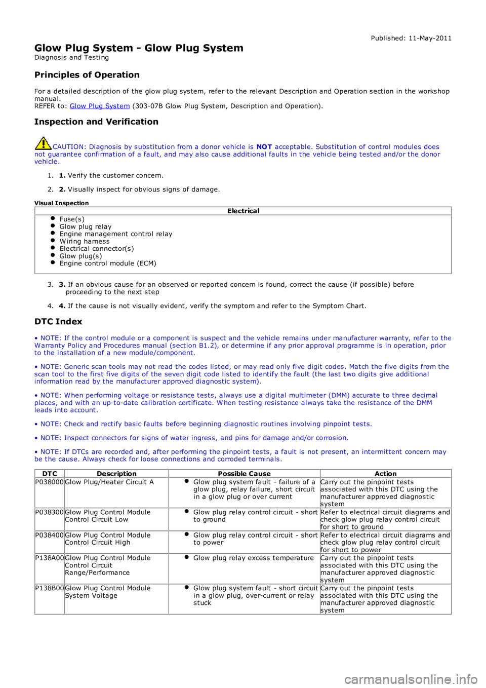
Glow Plug System - Glow Plug System
Diagnosi s and Tes ti ng
Principles of Operation
For a detail ed descripti on of the gl ow plug sys tem, refer t o t he rel evant Des cript ion and Operat ion s ecti on in the works hopmanual.REFER to: Gl ow Plug Sys tem (303-07B Glow Pl ug Syst em, Des cript ion and Operat ion).
Inspection and Verification
CAUTION: Di agnos is by s ubs ti tut ion from a donor vehicle is NO T acceptabl e. Subs ti tut ion of cont rol modules doesnot guarant ee confirmat ion of a faul t, and may als o caus e addit ional fault s i n t he vehi cl e being t est ed and/or t he donorvehi cl e.
1. Verify t he cus t omer concern.1.
2. Vis ually ins pect for obvious s igns of damage.2.
Visual InspectionElectrical
Fuse(s )Gl ow plug relayEngine management cont rol rel ayW iri ng harnes sElectrical connect or(s )Gl ow plug(s )Engine control modul e (ECM)
3. If an obvious cause for an obs erved or report ed concern is found, correct t he caus e (if pos s ible) beforeproceeding t o t he next s t ep3.
4. If t he caus e is not vis ually evi dent , verify t he sympt om and refer t o t he Sympt om Chart.4.
DTC Index
• NOTE: If the control modul e or a component i s s us pect and the vehicle remains under manufacturer warrant y, refer t o theW arranty Pol icy and Procedures manual (s ect ion B1.2), or determine i f any pri or approval programme is in operat ion, pri ort o the ins tall ati on of a new module/component.
• NOTE: Generic scan t ool s may not read the codes li st ed, or may read only fi ve digit codes . Mat ch the five di git s from t hes can tool to the firs t fi ve di git s of the seven digi t code l is ted to ident ify t he faul t (t he las t t wo digi ts gi ve addi ti onalinformat ion read by the manufact urer approved diagnos t ic s ys tem).
• NOTE: W hen performing volt age or res is t ance t est s , always use a digi tal mult imeter (DMM) accurat e t o t hree deci malplaces, and wi th an up-t o-date cal ibrat ion cert ificate. W hen tes ti ng res is t ance al ways take t he res is t ance of t he DMMleads i nt o account .
• NOTE: Check and recti fy bas ic faul ts before beginni ng diagnos t ic rout ines i nvol vi ng pinpoint t es t s.
• NOTE: Ins pect connect ors for s igns of water ingres s , and pins for damage and/or corros ion.
• NOTE: If DTCs are recorded and, aft er performi ng the pi npoi nt tes ts , a fault is not present , an int ermi tt ent concern maybe t he caus e. Always check for loose connect ions and corroded terminals .
DT CDescriptionPossible CauseAction
P038000Gl ow Plug/Heat er Circuit AGl ow plug s ys tem fault - fail ure of aglow plug, rel ay fail ure, s hort circuiti n a gl ow plug or over current
Carry out t he pinpoint t es t sas s oci ated wi th thi s DTC us ing t hemanufact urer approved diagnos t ics ys tem
P038300Gl ow Plug Cont rol Modul eControl Circuit LowGl ow plug relay control ci rcuit - s hortt o groundRefer to el ect ri cal circui t diagrams andcheck glow pl ug rel ay cont rol ci rcuitfor s hort to ground
P038400Gl ow Plug Cont rol Modul eControl Circuit Hi ghGl ow plug relay control ci rcuit - s hortt o powerRefer to el ect ri cal circui t diagrams andcheck glow pl ug rel ay cont rol ci rcuitfor s hort to powerP138A00Gl ow Plug Cont rol Modul eControl CircuitRange/Performance
Gl ow plug relay exces s t emperat ureCarry out t he pinpoint t es t sas s oci ated wi th thi s DTC us ing t hemanufact urer approved diagnos t ics ys temP138B00Gl ow Plug Cont rol Modul eSys tem Vol tageGl ow plug s ys tem fault - short ci rcuiti n a gl ow plug, over-current or relays t uck
Carry out t he pinpoint t es t sas s oci ated wi th thi s DTC us ing t hemanufact urer approved diagnos t ics ys tem
Page 1556 of 3229
Publi shed: 13-Jul-2011
Fuel Tank and Lines - I6 3.2L Petrol - Fuel Tank and Lines
Diagnosi s and Tes ti ng
Principles of Operation
For a detail ed descripti on of the fuel tank and l ines s ys t ems , refer t o t he rel evant Des cript ion and Operat ion s ecti on in theworks hop manual .REFER to: Fuel Tank and Lines (310-01A Fuel Tank and Lines - I6 3.2L Pet rol , Descri pti on and Operat ion).
Inspection and Verification
CAUTION: Di agnos is by s ubs ti tut ion from a donor vehicle is NO T acceptabl e. Subs ti tut ion of cont rol modules doesnot guarant ee confirmat ion of a faul t, and may als o caus e addit ional fault s i n t he vehi cl e being t est ed and/or t he donorvehi cl e.
• NOTE: For di agnos t ic purpos es the cyli nders are divided i nt o t wo banks: Bank 1 - Cyl inder numbers 1, 2 and 3. Bank 2 -Cylinders 4, 5 and 6
1. Verify t he cus t omer concern.1.
2. Vis ually ins pect for obvious s igns of mechani cal or electrical damage.2.
Visual Inspection
MechanicalElectricalFuel l eaksDamaged fuel l inesDamaged push connect fit t ingsFuel l evelFuel contami nati on/grade/quali tyDamaged fuel t ank fi ller pipe capDamaged fuel t ank fi ller pipe
FusesLoos e or corroded elect rical connect orsHarnes s esFuel Pump Dri ver Module (FPDM)Central Junct ion Box (CJB)Fuel pump relayEngine Control Modul e (ECM)
3. If an obvious cause for an obs erved or report ed concern is found, correct t he caus e (if pos s ible) beforeproceeding t o t he next s t ep.3.
4. If t he caus e is not vis ually evi dent , verify t he sympt om and refer t o t he Sympt om Chart, al ternat ively, check forDi agnos ti c Trouble Codes (DTCs) and refer t o t he DTC Index.4.
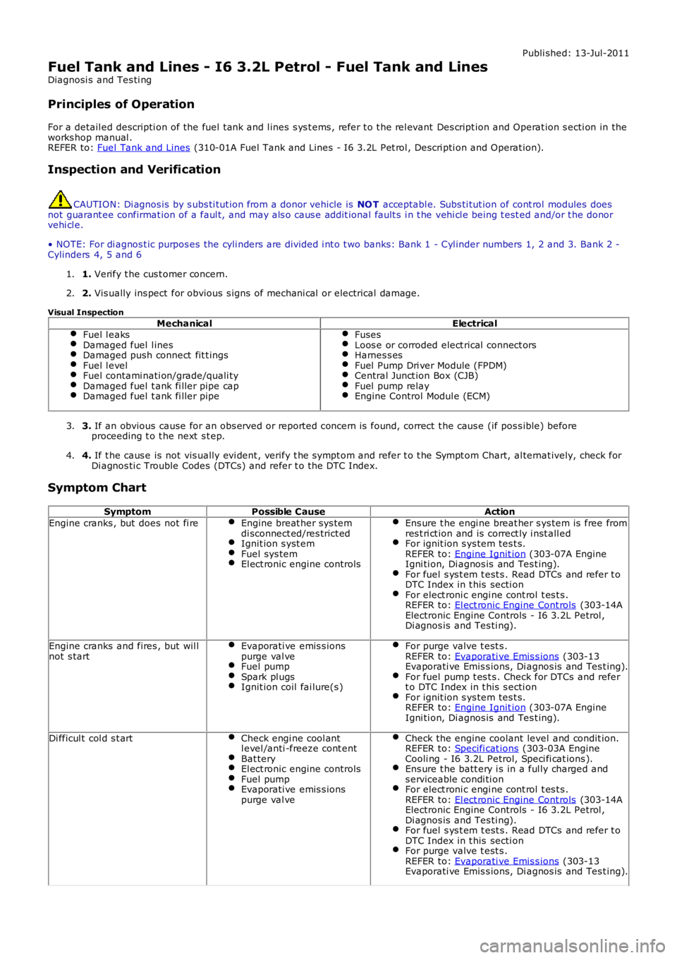
Symptom Chart
SymptomPossible CauseAction
Engine cranks , but does not fi reEngine breat her sys temdi sconnect ed/res trict edIgnit ion s yst emFuel sys temEl ect ronic engine controls
Ens ure t he engi ne breat her s ys tem is free fromres t ri ct ion and is correct ly i nst all edFor ignit ion s ys tem tes t s.REFER to: Engine Ignit ion (303-07A EngineIgni ti on, Di agnos is and Tes t ing).For fuel s ys t em t est s . Read DTCs and refer t oDTC Index in t his secti onFor elect roni c engi ne cont rol t es t s .REFER to: El ect ronic Engine Cont rols (303-14AElectronic Engine Controls - I6 3.2L Petrol ,Di agnos is and Tes ti ng).
Engine cranks and fires , but wil lnot s tartEvaporati ve emis s ionspurge val veFuel pumpSpark pl ugsIgnit ion coil fai lure(s )
For purge valve t est s .REFER to: Evaporati ve Emis s ions (303-13Evaporati ve Emis s ions, Di agnos is and Tes t ing).For fuel pump t es t s . Check for DTCs and refert o DTC Index in t his s ecti onFor ignit ion s ys tem tes t s.REFER to: Engine Ignit ion (303-07A EngineIgni ti on, Di agnos is and Tes t ing).
Di fficul t col d s t artCheck engi ne cool antl evel /anti -freeze cont entBat teryEl ect ronic engine controlsFuel pumpEvaporati ve emis s ionspurge val ve
Check the engine coolant level and condit ion.REFER to: Specifi cat ions (303-03A EngineCooli ng - I6 3.2L Petrol, Speci fi cat ions ).Ens ure t he batt ery i s in a ful ly charged ands erviceable condi ti onFor elect roni c engi ne cont rol t es t s .REFER to: El ect ronic Engine Cont rols (303-14AElectronic Engine Controls - I6 3.2L Petrol ,Di agnos is and Tes ti ng).For fuel s ys t em t est s . Read DTCs and refer t oDTC Index in t his secti onFor purge valve t est s .REFER to: Evaporati ve Emis s ions (303-13Evaporati ve Emis s ions, Di agnos is and Tes t ing).
Page 1591 of 3229
Publi s hed: 11-May-2011
Fuel Tank and Lines - TD4 2.2L Diesel - Fuel Tank and Lines
Diagnosi s and Tes ti ng
Principles of Operation
For a detail ed descripti on of the fuel tank and l ines s ys t ems , refer t o t he rel evant Des cript ion and Operat ion s ecti on in the
works hop manual .
REFER to: Fuel Tank and Lines (310-01B Fuel Tank and Lines - TD4 2.2L Dies el, Des cript ion and Operat ion).
Inspection and Verification CAUTION: Di agnos is by s ubs ti tut ion from a donor vehicle is
NO T acceptabl e. Subs ti tut ion of cont rol modules does
not guarant ee confirmat ion of a faul t, and may als o caus e addit ional fault s i n t he v ehi cl e being t est ed and/or t he donor
vehi cl e.
1. Verify t he cus t omer concern.
1.
2. Vis ually ins pect for obvious s igns of mechani cal or electrical damage.
2.
Visual Inspection Mechanical Electrical
Fuel l eaks Damaged fuel l ines
Damaged push connect fit t ings
Fuel l evel
Fuel contami nati on/grade/quali ty
Damaged fuel t ank fi ller pipe cap
Damaged fuel t ank fi ller pipe Fuses
Loos e or corroded elect rical connect ors
Harnes s es
Fuel Pump Dri ver Module (FPDM)
Central Junct ion Box (CJB)
Fuel pump relay
Engine Control Modul e (ECM)
3.
If an obvious cause for an obs erved or report ed concern is found, correct t he caus e (if pos s ible) before
proceeding t o t he next s t ep.
3.
4. If t he caus e is not vis ually evi dent , verify t he sympt om and refer t o t he Sympt om Ch art, al ternat ively, check for
Di agnos ti c Trouble Codes (DTCs) and refer t o t he DTC Index.
4.
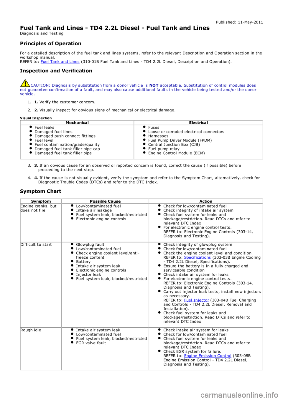
Symptom Chart Symptom Possible Cause Action
Engine cranks , but
does not fi re Low/contaminated fuel Intake air l eakage
Fuel sys tem leak, blocked/res tricted
El ect ronic engine controls Check for l ow/contami nat ed fuel
Check int egrit y of i nt ake air s yst em
Check fuel s yst em for leaks and
bl ockage/res t ri ct ion. Read DTCs and refer to
relevant DTC Index For electronic engine control t es ts .
REFER t o: Electroni c Engi ne Control s (303-14,
Diagnos is and Tes t ing). Di fficul t t o s tart
Gl owpl ug faul t Low/contaminated fuel
Check engi ne cool ant l evel /anti -
freeze cont ent Bat tery
Intake air s ys tem leak
El ect ronic engine controls
Injector l eak
Fuel sys tem leak, blocked/res tricted Check int egrit y of glowpl ug sys t em
Check for l ow/contami nat ed fuel
Check t he engi ne cool ant l evel and condi ti on.
REFER t o: Specificati ons (303-03B Engine Cool ing
- TD4 2.2L Di es el, Specificat ions ). Ens ure the bat tery is i n a full y charged and
servi ceable condit ion Check int ake air s yst em for leaks
For electronic engine control t es ts .
REFER t o: Electroni c Engi ne Control s (303-14,
Diagnos is and Tes t ing). Carry out i njector leak t est s , ins tal l new inject ors
as neces sary.
REFER t o: Fuel Injector (303-04B Fuel Charging
and Cont rols - TD4 2.2L Di esel , Removal and
Ins tal lati on). Check fuel s yst em for leaks and
bl ockage/res t ri ct ion. Read DTCs and refer to
relevant DTC Index Rough idl e
Intake air s ys tem leak Low/contaminated fuel
Fuel sys tem leak, blocked/res tricted
EGR val ve fault Check int ake air s yst em for leaks
Check for l ow/contami nat ed fuel
Check fuel s yst em for leaks and
bl ockage/res t ri ct ion. Read DTCs and refer to
relevant DTC Index Check EGR s ys tem for fai lure.
REFER t o: Engi ne Emis s ion Cont rol (303-08B
Engine Emis s ion Control - TD4 2.2L Di esel ,
Diagnos is and Tes t ing).
Page 1933 of 3229
• NOTE: Generic scan t ool s may not read the codes li st ed, or may read only 5-digi t codes . Match t he 5 digi ts from t he s cant ool t o t he fi rs t 5 di gi ts of the 7-digit code li s ted t o i dent ify the fault (the last 2 digi ts gi ve ext ra informati on read by themanufacturer-approved di agnos ti c s ys t em).
• NOTE: Check and recti fy bas ic faul ts before beginni ng diagnos t ic rout ines i nvol vi ng pinpoint t es t s.
• NOTE: Ins pect connect ors for s igns of water ingres s , and pins for damage and/or corros ion.
• NOTE: If DTCs are recorded and, aft er performi ng the pi npoi nt tes ts , a fault is not present , an int ermi tt ent concern maybe t he caus e. Always check for loose connect ions and corroded terminals .
• NOTE: Pri or to ins tall ati on/replacement of the Headlamp Ass embly carry out all relevant i nternal vis ual and mechanicalchecks for correct cable l ocat ion and t erminati on including: checks for corroded, bent or backed out pi ns or terminals ,incorrect ly i nserted connect ors and harnes s damage due t o chaffi ng or incorrect routing.
• NOTE: If the control modul e has been removed and rei nst all ed, carry out a DTC code clear, cycl e t he ignit ion st ate to off,t hen on. This will erase any DTCs that have been l ogged during t he module ins tall ation procedure
For a compl ete lis t of all Di agnos ti c Trouble Codes (DTCs) t hat could be logged on this vehicle, pleas e refer to Sect ion100-00.
REFER to: Di agnos ti c Trouble Code (DTC) Index - DTC: Headlamp Cont rol Modul e (HCM) (100-00 General Informati on,Des cript ion and Operat ion).
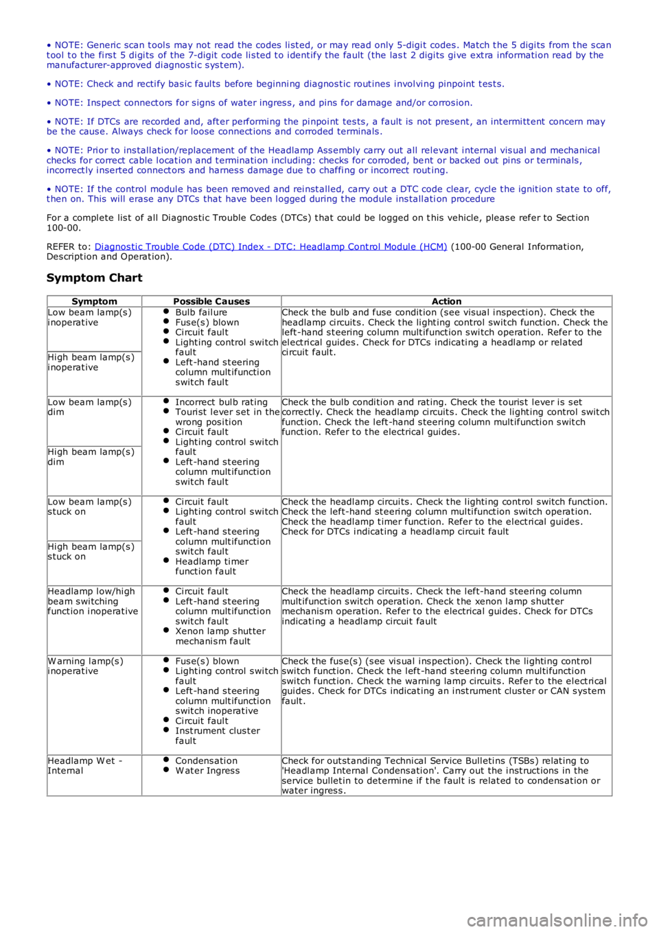
Symptom Chart
SymptomPossible CausesActionLow beam lamp(s )i noperat iveBulb fail ureFus e(s ) blownCi rcuit faul tLight ing control s wi tchfaul tLeft -hand s t eeringcolumn mult ifuncti ons wit ch faul t
Check t he bulb and fuse condit ion (s ee vis ual i nspecti on). Check theheadlamp ci rcuit s . Check t he li ght ing control swit ch funct ion. Check theleft -hand s t eering column mult ifunct ion s wi tch operat ion. Refer to theel ect ri cal guides . Check for DTCs indicati ng a headl amp or rel atedci rcuit faul t.Hi gh beam lamp(s )i noperat ive
Low beam lamp(s )dimIncorrect bul b rat ingTouri st l ever s et in thewrong pos i ti onCi rcuit faul tLight ing control s wi tchfaul tLeft -hand s t eeringcolumn mult ifuncti ons wit ch faul t
Check t he bulb condi ti on and rat ing. Check the t ouris t l ever i s s etcorrectl y. Check the headlamp ci rcuit s . Check t he li ght ing control swit chfunct ion. Check the l eft -hand s teering column mult ifuncti on s wit chfunct ion. Refer t o t he electrical gui des .
Hi gh beam lamp(s )dim
Low beam lamp(s )s tuck onCi rcuit faul tLight ing control s wi tchfaul tLeft -hand s t eeringcolumn mult ifuncti ons wit ch faul tHeadlamp ti merfunct ion faul t
Check t he headl amp circui ts . Check t he l ighti ng cont rol s wit ch functi on.Check t he left-hand st eeri ng col umn mul ti funct ion swi tch operat ion.Check t he headl amp t imer funct ion. Refer to the el ect ri cal guides .Check for DTCs i ndicat ing a headl amp circui t fault
Hi gh beam lamp(s )s tuck on
Headlamp l ow/hi ghbeam s wi tchingfunct ion i noperat ive
Ci rcuit faul tLeft -hand s t eeringcolumn mult ifuncti ons wit ch faul tXenon lamp s hut termechani s m fault
Check t he headl amp circui ts . Check t he l eft-hand s teeri ng col umnmult ifunct ion s wit ch operati on. Check t he xenon l amp s hutt ermechanis m operati on. Refer t o t he electrical gui des . Check for DTCsindicati ng a headl amp circui t fault
W arning l amp(s )i noperat iveFus e(s ) blownLight ing control s wi tchfaul tLeft -hand s t eeringcolumn mult ifuncti ons wit ch inoperat iveCi rcuit faul tInst rument clus t erfaul t
Check t he fus e(s ) (s ee vi s ual i ns pecti on). Check t he li ghti ng cont rolswi tch funct ion. Check t he l eft -hand s teeri ng column mul ti functi onswi tch funct ion. Check t he warni ng lamp circuit s . Refer to the el ect ri calgui des . Check for DTCs indicat ing an i nst rument clus ter or CAN s ys temfault .
Headlamp W et -InternalCondens ati onW at er Ingres sCheck for out st anding Techni cal Service Bull eti ns (TSBs ) rel at ing to'Headl amp Internal Condens ati on'. Carry out the i nst ruct ions in theservi ce bullet in to det ermi ne if t he faul t is relat ed to condens at ion orwater ingres s .
Page 2189 of 3229
Publi shed: 26-Jul-2011
Seating - Heater Mats
Diagnosi s and Tes ti ng
Principles of Operation
Heated s eats incorporate heat er elements in t he cushi on and the backres t of the s eat. Each cus hion heat er el ement has at hermal sens or, whi ch suppli es a feedback temperat ure si gnal t o t he rel at ed s eat heat er modul e. The backres t heat erelement s do not have a thermal sens or, and are regulat ed at the s ame temperat ure as the cus hi on heat er elements .
For a detail ed descripti on of the seat heater mat , refer t o t he rel evant Des cript ion and Operat ion s ecti on in the workshopmanual. REFER to: Seats (501-10, Descripti on and Operat ion).
Inspection and Verification
1. Verify t he cus t omer concern.1.
2. Vis ually ins pect for obvious s igns of mechani cal or electrical damage.2.
Visual inspectionMechanicalElectrical
Seat heat er swi tches condi ti on and ins tal lati onFusesHarnes s es and connect orsSeat heat er modul eSeat heat er swi tchesSeat heat er mat
3. If an obvious cause for an obs erved or report ed concern is found, correct t he caus e (if pos s ible) beforeproceeding t o t he next s t ep.3.
4. If t he caus e is not vis ually evi dent , verify t he sympt om and refer t o t he Sympt om Chart.4.
• NOTE: If the control modul e or a component i s s us pect and the vehicle remains under manufacturer warrant y, refer t o thewarranty poli cy and procedures manual (s ect ion B1.2), or det ermine i f any prior approval programme is i n operati on, priort o the ins tall ati on of a new module/component.
• NOTE: Generic scan t ool s may not read the codes li st ed, or may read only fi ve digit codes . Mat ch the five di git s from t hes can tool to the firs t fi ve di git s of the seven digi t code l is ted to ident ify t he faul t (t he las t t wo digi ts gi ve addi ti onalinformat ion read by the manufact urer approved diagnos t ic s ys tem).
• NOTE: W hen performing el ect ri cal volt age or resi s tance tes t s, al ways us e a digit al mult imet er (DMM) accurate to threedeci mal places , and wi th an up-to-date cali brat ion cert ificate. W hen t es ti ng res is t ance, always take t he res i st ance of t heDMM leads int o account.
• NOTE: Check and recti fy bas ic faul ts before beginni ng diagnos t ic rout ines i nvol vi ng pinpoint t es t s.
• NOTE: Ins pect connect ors for s igns of water ingres s , and pins for damage and/or corros ion.
• NOTE: If DTCs are recorded and, aft er performi ng the pi npoi nt tes ts , a fault is not present , an int ermi tt ent concern maybe t he caus e. Always check for loose connect ions and corroded terminals .
DTC Index
For a compl ete lis t of all di agnos ti c troubl e codes that coul d be l ogged on t his vehicle, pleas e refer to s ect ion 100-00.
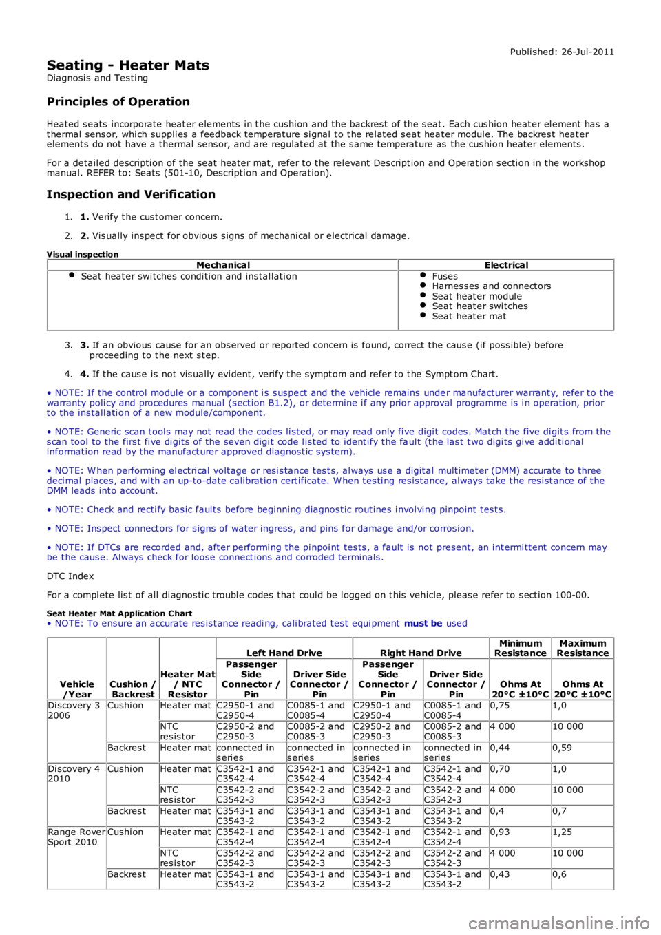
Seat Heater Mat Application C hart• NOTE: To ens ure an accurate res is t ance readi ng, cali brated tes t equi pment must be used
Vehicle/YearCushion /Backrest
Heater Mat/ NT CResistor
Left Hand DriveRight Hand DriveMinimumResistanceMaximumResistance
PassengerSideConnector /Pin
Driver SideConnector /Pin
PassengerSideConnector /Pin
Driver SideConnector /PinOhms At20°C ±10°COhms At20°C ±10°CDi scovery 32006Cushi onHeater matC2950-1 andC2950-4C0085-1 andC0085-4C2950-1 andC2950-4C0085-1 andC0085-40,751,0
NTCres is t orC2950-2 andC2950-3C0085-2 andC0085-3C2950-2 andC2950-3C0085-2 andC0085-34 00010 000
Backres tHeater matconnect ed ins eri esconnect ed ins eri esconnect ed i nseriesconnect ed inseries0,440,59
Di scovery 42010Cushi onHeater matC3542-1 andC3542-4C3542-1 andC3542-4C3542-1 andC3542-4C3542-1 andC3542-40,701,0
NTCres is t orC3542-2 andC3542-3C3542-2 andC3542-3C3542-2 andC3542-3C3542-2 andC3542-34 00010 000
Backres tHeater matC3543-1 andC3543-2C3543-1 andC3543-2C3543-1 andC3543-2C3543-1 andC3543-20,40,7
Range RoverSport 2010Cushi onHeater matC3542-1 andC3542-4C3542-1 andC3542-4C3542-1 andC3542-4C3542-1 andC3542-40,931,25
NTCres is t orC3542-2 andC3542-3C3542-2 andC3542-3C3542-2 andC3542-3C3542-2 andC3542-34 00010 000
Backres tHeater matC3543-1 andC3543-2C3543-1 andC3543-2C3543-1 andC3543-2C3543-1 andC3543-20,430,6
Page 2452 of 3229
Publi s hed: 21-Nov-2011
Safety Belt System - Safety Belt System
Diagnosi s and Tes ti ng
Principle of Operation
For a detail ed descripti on of the safet y belt s ys tem and operati on, refer t o t he relevant des cri pti on and operati on s ect ionof the workshop manual REFER to: Safet y Belt Sys tem (501-20A Safety Bel t Sys t em, Des cri pti on and Operati on).
Safety Information
• W ARNINGS:
To avoid accidental depl oyment t he back-up power supply must be depl et ed before begi nning any work on the SRSs ys t em or i ts component s . Fai lure to foll ow t his i nst ruct ion may res ul t in pers onal injury
Do not us e a mult imet er to probe an SRS module. It is pos s ible for the power from the mult imet er bat tery t o triggert he act ivati on of the modul e. Fai lure to foll ow t his i ns t ructi on may resul t in personal injury
• NOTE: Do not t o us e a cell ul ar phone or t o have a cell ul ar phone i n clos e proximity when worki ng on the SRS sys t em orcomponents
Power supply deplet ion
Before begi nni ng any work on the SRS sys tem or rel at ed component s:
1. Remove the i gnit ion key1.
2. Dis connect the bat tery leads , ground fi rs t2.
3. W ait 2 mi nut es for t he power ci rcuit t o dis charge3.
There are comprehens i ve ins truct ions on t he correct procedures for SRS s ys tem repairs , refer t o t he rel evant s ect ion of t heworks hop manual
Inspection and Verification
CAUTION: Di agnos is by s ubs ti tut ion from a donor vehicle is NO T acceptabl e. Subs ti tut ion of cont rol modules doesnot guarant ee confirmat ion of a faul t and may al so caus e addit ional fault s in the vehicle bei ng checked and/or the donorvehi cl e
• NOTE: Check and recti fy bas ic faul ts before beginni ng diagnos t ic rout ines i ncl udi ng pinpoint t es t s
1. Verify t he cus t omer concern by operat ing t he s afet y belt1.
2. Vis ually ins pect for obvious s igns of mechani cal or electrical damage2.
Visual InspectionMechanicalElectrical
Check for t he ins tal lati on of non-s tandard acces s ori es which may affect orobs truct t he functi on of the safet y belt s ys temFrayed or damaged webbi ngMi ss i ng or damaged but ton s t opPret ensi oner(s ) Buckl es/Stal ks
FusesW iri ng harnes s faultCorrect engagement ofelectrical connect orsLoose or corroded connect ionsW arning l amp bulb(s)Impact s ens or(s )Buckl e s ens or(s )Pret ensi oner(s )Belt t ensi on s ens or(s )Res traints cont rol module
3. If an obvious cause for an obs erved or report ed concern is found, correct t he caus e (if pos s ible) beforeproceeding t o t he next s t ep3.
4. If t he caus e is not vis ually evi dent , carry out t he t es t met hods des cri bed bel ow, alternat ively check fordi agnos ti c troubl e codes and refer t o t he rel evant diagnost ic troubl e code index4.
For a compl ete lis t of all di agnos ti c troubl e codes that coul d be l ogged on t his vehicle, pleas e refer to s ect ion 100-00.REFER to: Di agnos ti c Trouble Code (DTC) Index - DTC: Res trai nts Cont rol Module (RCM) (100-00 General Informati on,Des cript ion and Operat ion).
Symptom Chart for Safety Belt Rows 1, 2 and 3
SymptomPossible CausesActionSafet y belt jammed -W ebbing ti ghtBackl ock effect-in act ion (webbing ret ract ed qui ckl yand came t o s udden st op)Safet y belt ret ract or not i ns t alled correctl yRear cent re bel t onl y. Mini-but t on (webbing travell imi t st op) mis s ing and seat s quab has been moved
GO t o Pi npoint Tes t A.GO t o Pi npoint Tes t F.GO t o Pi npoint Tes t H.See the aut omati c lockingret ractor des cript ion below
Page 2725 of 3229

Contents
5
R
ENGINE COOLANT CHECK ............................ 163
BRAKE AND CLUTCH FLUID CHECK ............. 165
POWER STEERING FLUID CHECK ................ 166
WASHER FLUID CHECK ................................ 167
TECHNICAL SPECIFICATIONS ...................... 169
Vehicle battery
BATTERY WARNING SYMBOLS ................... 171
BATTERY CARE ............................................ 171
USING BOOSTER CABLES ............................ 173
CHARGING THE VE HICLE BATTERY ............. 174
CHANGING THE VE HICLE BATTERY ............. 174
Wheels and tyres
GENERAL INFORMATION ............................. 176
TYRE CARE ................................................... 177
USING WINTER TYRES................................. 183
CHANGING A ROAD WHEEL ......................... 183
TYRE REPAIR KIT ......................................... 187
USING SNOW CHAINS.................................. 192
TYRE GLOSSARY.......................................... 193
TECHNICAL SPECIFICATIONS ...................... 194
Fuses
FUSE BOX LOCATIONS ................................. 195
CHANGING A FUSE ....................................... 195
FUSE SPECIFICATION CHART....................... 196
Emergency equipment
HAZARD WARNING FLASHERS .................... 204
WARNING TRIANGLE ................................... 204
Status after a collision
DRIVING AFTER A COLLISION...................... 205
INSPECTING SAFETY SYSTEM COMPONENTS ...
206
Vehicle recovery
TOWING POINTS .......................................... 207
LASHING POINTS ......................................... 208
TRANSPORTING THE VEHICLE..................... 208
TOWING THE VEHICLE ON FOUR WHEELS .. 208
Vehicle identification
VEHICLE IDENTIFICATION PLATE................. 210
VEHICLE IDENTIFI CATION NUMBER (VIN) ... 210
VEHICLE BUILD DATE PLATE ....................... 210
Technical specifications
ENGINE SPECIFICATIONS ............................ 211
WEIGHTS...................................................... 212
DIMENSIONS................................................ 213
Type approval
Declarations of conformity ........................... 215
Audio introduction
RADIO RECEPTION....................................... 218
Audio unit overview
AUDIO UNIT OVERVIEW............................... 219
Audio unit operation
ON OR OFF CONTROL .................................. 223
VOLUME CONTROL ...................................... 223
AUDIO CONTROL ......................................... 223
WAVEBAND BUTTON ................................... 224
AUTOSTORE CONTROL ................................ 225
STATION PRESET BUTTONS ........................ 226
TRAFFIC INFORMATION CONTROL .............. 226
Audio unit menus
RADIO DATA SYSTEM (RDS) ....................... 228
REGIONAL MODE (REG) .............................. 228
ENHANCED OTHER NETWORK (RDS-EON).. 229
ALTERNATIVE FREQUENCIES ...................... 229
NEWS BROADCASTS ................................... 230
PRIORITY PROGRAMME TYPE (PTY) .......... 231
RESETTING THE AUDIO UNIT ...................... 233
Digital audio broadcasting
GENERAL INFORMATION ............................. 234
AUDIO CONTROLS ....................................... 235
DISPLAY OPTIONS ....................................... 236
CHANNEL AUTOMATIC TUNING................... 236
CHANNEL OPTIONS ..................................... 236
PRESET BUTTONS ....................................... 238
SETTINGS..................................................... 240
Compact disc player
LOADING COMPACT DISCS ......................... 245
EJECTING COMPACT DISCS ........................ 246
EJECTING MULTIPLE CO MPACT DISCS....... 246
COMPACT DISC SELECTION ........................ 246
COMPACT DISC PLAYBACK ......................... 246