ignition LAND ROVER FRELANDER 2 2006 Repair Manual
[x] Cancel search | Manufacturer: LAND ROVER, Model Year: 2006, Model line: FRELANDER 2, Model: LAND ROVER FRELANDER 2 2006Pages: 3229, PDF Size: 78.5 MB
Page 44 of 3229
Publi s hed: 11-May-2011
General Information - Road/Roller Testing
Des cript ion and Operat ion
Road or roll ing road t es t ing may be carri ed out for various reasons and a procedure det ail ing pre-t es t checks , throughengi ne s tarti ng and s topping, pre-driving checks , on-t es t checks to final checks on complet ion of t he tes t are given.
Unles s complete vehi cl e performance is bei ng checked, t he ful l road t est procedure need not be carried out . Ins tead, t hos eit ems part icularly relevant t o t he s yst em(s) bei ng checked can be ext racted.
Pre-Test Checks
W ARNING: If t he brake s yst em hydraul ic fluid level i s l ow, pedal travel i s exces si ve or a hydraulic leak is found, donot att empt to road t est t he vehicle unt il t he reas on for t he low fl ui d l evel, excess ive pedal travel or hydraulic leak isfound and rect ified.
It is s ugges t ed that pre-t es t and funct ional t es ts of t hose sys tems/circuit s whi ch affect t he safe and l egal operati ons oft he vehi cl e, s uch as brakes , light s and s teeri ng, should al ways be carri ed out before the road or roll ing road tes t .
Engi ne oil l evelEngi ne cool ant levelTires, for correct pres sure, compat ible types and tread patt erns , and wear wi thi n limi ts .There i s s ufficient fuel in the t ank to compl ete the t est .Check al l around the engine, t rans mis s ion and under the vehicle for oil , coolant , hydraul ic and fuel l eaks . Make anote of any apparent leaks and wipe off t he surrounding areas t o make it easi er to identi fy t he extent of the leakon complet ion of t he tes t.
Starting the Engine
• NOTE: On i nit ial dri ve away from cold and wit hi n t he fi rs t 1.5 km (1 mile), do not depress accelerat or pedal beyond halft ravel unt il t he vehi cl e has att ained a minimum s peed of 25 km/h (15 mil es /h). Never operat e at high engi ne speed or wi tht he accelerat or pedal at ful l travel whil st the engine i s cold.
With the ignition off, check:
The parking brake is appli ed.Automatic transmission: The s el ect or lever is i n 'P' - PARK.Manual transmission: The gear l ever i s in NEUTRAL.All i ns t rument gauges read zero.
With the ignition on, check:
Igni ti on cont roll ed warni ng li ght s come on.Engi ne t emperature gauge regis t ers a readi ng compat ibl e wi th t he engine t emperat ure.Fuel gauge regi st ers a reading appropriate to the fuel l evel i n t he tank.The operati on of the parki ng brake warning l ight and fl ui d l evel warni ng indicator light.
On Road Test Check:
CAUTION: At commencement of road tes ti ng, check the brake operati on while s ti ll travel li ng at low speed beforecont inuing wit h t he tes t. If t he brakes pul l to one si de, or appear to be ot herwi se fault y, do not cont inue wit h t he roadt es t unti l the fault has been found and rect ified.
The parking brake releas es completel y.Gear changing i s s mooth, and t here are no abnormal noi s es or vi brati ons from t he t rans mis s ion.The engi ne power out put is s ati s factory, accel erati on is smoot h and accel erator pedal operat ion is not s ti ff orheavy, and engi ne s peed ret urns t o idl e correctl y.There i s no exces s ive or abnormall y colored s moke from t he engi ne under normal driving, heavy l oad or overruncondi ti ons .Steering operat ion i s s moot h, accurat e, not exces s ively heavy or wit h exces s ive free pl ay or vibrat ion. Does not pul lt o one s ide and s elf centres smoot hly after corneri ng.All i ns t rument s regis t er the correct readi ngs and operate correctl y.Swit ches and controls operat e s moothl y and posi ti vel y, warning or i ndi cat or light s operate correctl y and thedirect ion i ndi cat or cont rol s elf cancels when the s t eering i s ret urned t o t he s traight ahead pos it ion.Heati ng and vent il at ion sys tems work correct ly and effect ively.Brakes operate efficientl y.
Brake Testing
Avoi d brake t es ti ng on busy roads where i t can caus e i nconveni ence or danger t o ot her road users.
CAUTION: Brake t es ti ng which i ncludes heavy brake appl icati ons should not be carri ed out wit h new brake pads /dis csunti l the component s have bedded-i n. New brake fri ct ion component s wi ll not reach ful l efficiency unt il t he beddi ng-inprocess is complet e. Not e t hat when new parking brake shoes or rear brake di scs have been ins t al led, it i s es sent ial thatt he 'beddi ng-in' procedure i s carri ed out.For addit ional informat ion, refer t o: Parking Brake Shoes Bedding-In (206-05 Parking Brake and Actuati on, GeneralProcedures).
Test t he brakes at s everal speeds wit hin the normal operat ing range usi ng both light and heavy pedal pres s ure. Note anyt endency to snat ch, pull or drag, and any undue del ay in appli cat ion or release.
Page 177 of 3229
For addit ional informat ion, refer t o: Parking Brake Cabl e Adjus tment (206-05 Parki ng Brake and Actuat ion, GeneralProcedures).
Door Locks and Hinges
1. Check operat ion of all door locks, bonnet lock and fuel fi ll er flap.
2. Lubricate al l door check s t raps , bonnet cat ch and fuel fill er fl ap cat ch.
Cooling System
CAUTION: Anti-freeze concentration must be maintained at 50%.
1. Check s peci fi c gravit y of cool ant us ing a hydrometer.
• NOTE: A s uit able hydromet er is avail abl e from the Equipment Programme under Part Number 511 3302 001 00.
2. Top-up cool ing s ys tem if neces s ary.For addit ional informat ion, refer t o: Specificati ons (303-03A Engine Cool ing - I6 3.2L Pet rol , Specificati ons ).
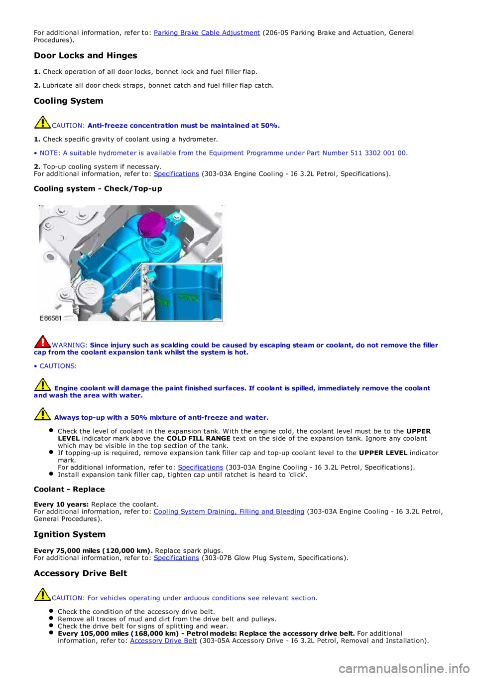
Cooling system - Check/Top-up
W ARNING: Since injury such as scalding could be caused by escaping steam or coolant, do not remove the fillercap from the coolant expansion tank whilst the system is hot.
• CAUTIO NS:
Engine coolant w ill damage the paint finished surfaces. If coolant is spilled, immediately remove the coolantand wash the area with water.
Always top-up with a 50% mixture of anti-freeze and water.
Check t he l evel of cool ant i n t he expans ion t ank. W it h t he engi ne col d, the coolant level must be to the UPPERLEVEL indicat or mark above the COLD FILL RANGE t ext on the s i de of the expans i on tank. Ignore any coolantwhich may be vis ible in t he t op s ect ion of t he t ank.If topping-up i s requi red, remove expans ion tank fill er cap and top-up coolant level to the UPPER LEVEL indicat ormark.For addit ional informat ion, refer t o: Specificati ons (303-03A Engine Cool ing - I6 3.2L Pet rol , Specificati ons ).Ins t all expans ion t ank fi ll er cap, ti ght en cap unti l ratchet is heard to 'cli ck'.
Coolant - Replace
Every 10 years: Repl ace the coolant.For addit ional informat ion, refer t o: Cool ing Sys tem Drai ning, Fi ll ing and Bl eeding (303-03A Engine Cooli ng - I6 3.2L Pet rol,General Procedures ).
Ignition System
Every 75,000 miles (120,000 km). Replace s park plugs .For addit ional informat ion, refer t o: Specificati ons (303-07B Glow Pl ug Sys t em, Specificati ons ).
Accessory Drive Belt
CAUTION: For vehi cl es operati ng under arduous condi ti ons s ee relevant s ecti on.
Check t he condi ti on of the access ory drive bel t.Remove all t races of mud and dirt from t he dri ve belt and pull eys .Check t he drive belt for si gns of s pli tt ing and wear.Every 105,000 miles (168,000 km) - Petrol models: Replace the accessory drive belt. For addi ti onalinformat ion, refer t o: Acces s ory Drive Belt (303-05A Acces s ory Drive - I6 3.2L Pet rol , Removal and Ins t allat ion).
Page 296 of 3229
programs.
Incorrect Program Usage
Selecti on of an inappropri at e program i s dis couraged in t he followi ng ways:
The act ive program icon is conti nual ly di spl ayed i n t he ins t rument clus ter mes s age centerThe Terrai n Res pons e control modul e 'l ocks ' out cert ain funct ions i n s ome programs, for exampl e:- cruis e control is only avai lable wi th the special programs off or gras s/gravel/s now program- t rans mis s ion 'Sport' mode i s deact ivated i n all s peci al programs .W hen t he i gni ti on has been in t he off mode, cont inuall y for more t han 6 hours , t he Terrai n Respons e s yst emdefault s t o t he special programs off.
Selecti on of an inappropri at e program for the t errain condit ions wil l not endanger the dri ver or cause damage to thevehi cl e. Cont inued us e of an inappropri ate program may reduce t he li fe of s ome component s . The driver may not icereduced vehi cl e res ponse, wi th the engine and t rans mi ss i on bei ng les s respons ive t han in s peci al programs off. Al so, i ns ome programs, HDC wil l remai n on, si gni fi ed by il lumi nat ion of t he HDC indicator in the i nst rument clus t er. The dri ver mayals o not ice t orque 'wi nd-up' i n t he act ive on-demand coupli ng caus ing a braking effect when the vehicl e is manoeuvred i ns ome s peci al programs .
Driver Information
The high-l ine i nst rument clus t er fit t ed to al l vehi cl es wit h Terrain Res pons e, cont ains a mess age center which di spl aysvehi cl e i nformat ion to t he driver. The mes s age cent er contai ns the Terrain Res ponse program icons which dis play t hecurrent ly s elected program. If no s ymbol i s dis played, no special program is sel ect ed and the sys tem is in 'Specialprograms off'.
Any required changes t o t he s ub-s ys t ems are al s o pass ed t o t he dri ver i n t he form of i ndi cat or ill uminat ion i n t heins t rument clus ter or appropriat e mes s ages i n t he mes s age center, 'HDC OFF' for example.
In certai n operati ng condi ti ons , t he Terrai n Res pons e s yst em al s o dis plays advi ce or warning mess ages to ens ure thedri ver i s us ing t he vehi cl e t o it s full potenti al, for example, s t eering angle is dis played i n t he mes sage center t o avoi ddri vi ng in deep rut s wit h s t eering l ock appli ed.
DIAGNOSTICS
The Terrai n Res pons e control modul e s tores informati on on detect ed Terrai n Respons e faul ts and CAN errors whi ch can beint errogat ed usi ng IDS. The Terrain Res ponse s ub-s ys t ems and t he ins trument cl ust er als o s tore informat ion relat ing t oCAN errors from t he Terrain Res pons e control modul e.
The cont rol module al s o s tores the mil es travel ed and ti me el aps ed for t he i ndi vi dual programs which can al so be ret ri evedus ing IDS. Thi s informat ion aids di agnos is of t he Terrain Res pons e s ys tem and als o provi des an indicati on of Terrai nRespons e s yst em abus e by t he dri ver whi ch can l ead to premat ure component failure.
This i nformat ion can al so be us ed to check cus t omer concerns , for exampl e, hi gh fuel cons umpt ion whi ch may be due t ocont inued us e of a cert ain program.
Terrain Response System Fault Diag nosis
Terrai n Res pons e relies on the correct funct ionali ty of t he 4 s ub-s ys tems . If one of the s ub-s ys tems develops a fault , theTerrai n Res pons e s ys tem wil l not funct ion, even though the fault i s NOT in t he Terrain Res pons e s ys tem.
T he T errain Response control module and rotary control should only be investigated if there are no apparent faultsin any of the sub-systems. If a fault in a sub-system is subsequently corrected, the T errain Response system willfunction normally after an ignition mode 1 and 2 (on and off) cycle.
Terrain Response Sub-System Faults
W hen a fault occurs i n a s ub-s yst em, t he dri ver i s alert ed by t he il lumi nat ion of a warning indicator and/or an appropri atemes s age for that s ub-s yst em in t he i ns t rument clus ter mes s age cent er. There wi ll be no warning of a Terrain Res ponses ys t em fault .
W hen a sub-sys t em faul t is present and t he dri ver at tempt s t o s el ect a different Terrain Res pons e program us i ng therot ary control or at t he next ignit ion mode 2 (on) cycl e, a mes sage 'SY STEM FAULT SPECIAL PROGRAMS NOT AVAILABLE'wil l appear in the mess age cent er. This impl ies t hat t he Terrain Res pons e s ys tem has a faul t, but only because asub-system fault is preventing its operation. Thi s mes sage will be di spl ayed for 5 s econds per ignit ion mode 2 cycl e, butis repeat ed i f a further s electi on is made by the driver usi ng t he Terrai n Respons e rot ary control or at t he next ignit ionmode 2 (on) cycle.
• NOTE: The mes s age 'SY STEM FAULT SPECIAL PRO GRAMS NOT AVAILABLE' can al so be generated by a fault i n t he Terrai nRespons e rot ary control or control modul e. Refer to the foll owing i nformat ion for det ail s of rot ary control or control modul efaul ts .
It is not possible for the T errain R esponse control module to cause any fault behavior (w arning indicator illuminationor message generation) in any of the 4 sub-systems. Illuminati on of a s ub-s ys t em warning i ndi cat or and/or as ub-s ys t em relat ed mes sage wi ll NEVER be ass ociated wit h a Terrain Res ponse cont rol module or Terrain Res pons es ys t em fault .
The s ub-s ys t em control modul es can det ect a fault wit h the CAN s ignal from t he Terrai n Res pons e control modul e. If afaul t in t he Terrain Res pons e s ys tem is det ect ed, the s ub-s ys tem cont rol modules wi ll operate in t he 'Special programs off's ett ing. The s ub-s ys t em control modul es wil l record a fault code for a fail ure of t he Terrai n Res pons e CAN si gnal . Thes efaul ts can be retrieved us ing IDS and wi ll provide us eful informat ion t o i ndi cat e i nves ti gat ion of t he Terrain Res pons econt rol module or t he CAN net work.
Terrain Response Rotary Control or Control Module Fault
Page 593 of 3229
Publi s hed: 11-May-2011
Steering Column Switches - Ignition Switch
Removal and Inst all ati on
Removal
Make t he SRS s ys t em s afe.
Refer t o: Standard W orks hop Pract ices (100-00 General Informat ion,Des cript ion and Operat ion).
1.
Remove t he dri ver l ower ai r bag modul e.
Refer t o: Dri ver Lower Air Bag Module (501-20B SupplementalRes traint Sys t em, Removal and Inst all at ion).
2.
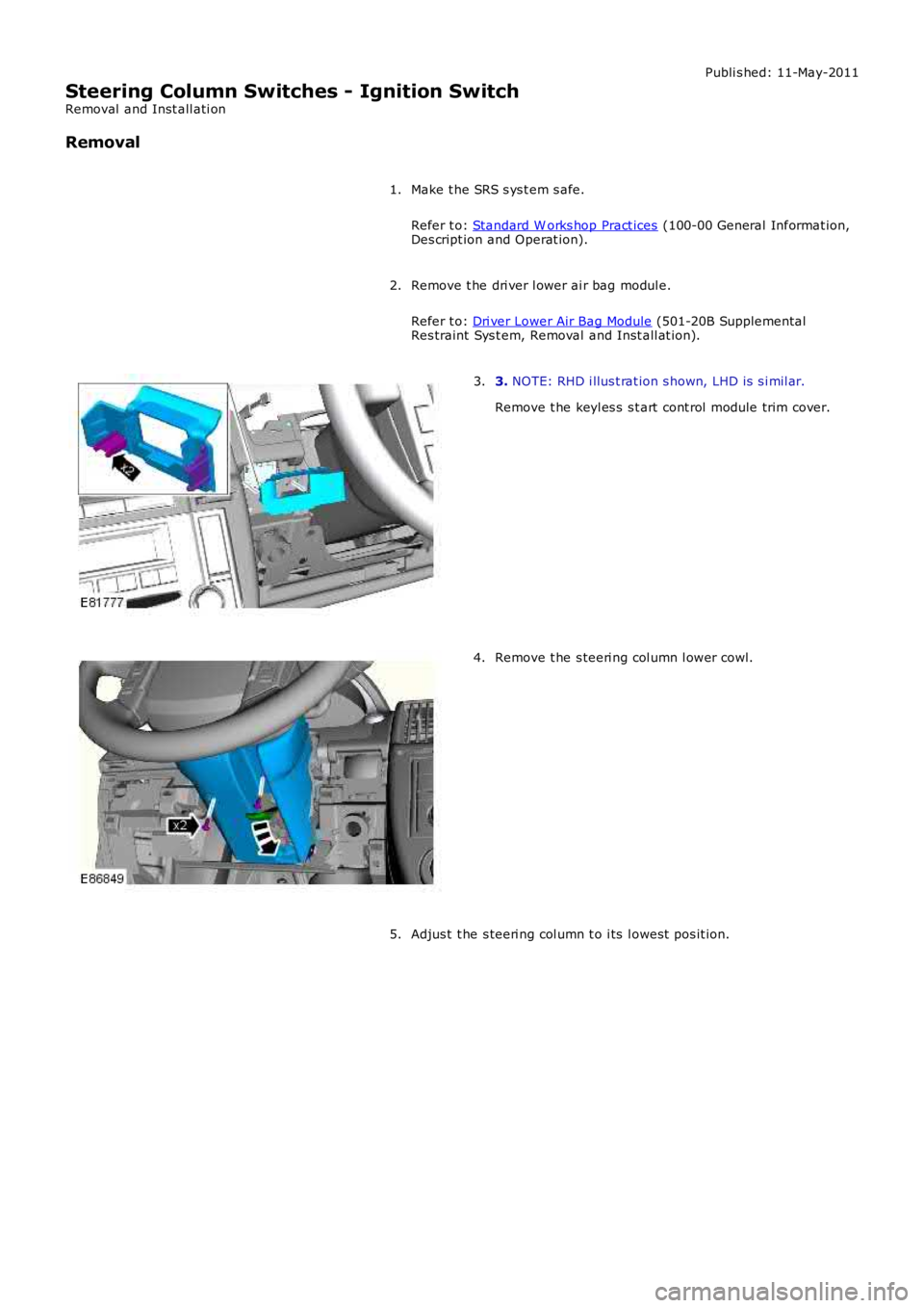
3. NOTE: RHD i llus t rat ion s hown, LHD is s i mil ar.
Remove t he keyl es s s t art cont rol module trim cover.
3.
Remove t he s teeri ng col umn l ower cowl.4.
Adjus t t he s teeri ng col umn t o i ts l owest pos it ion.5.
Page 624 of 3229
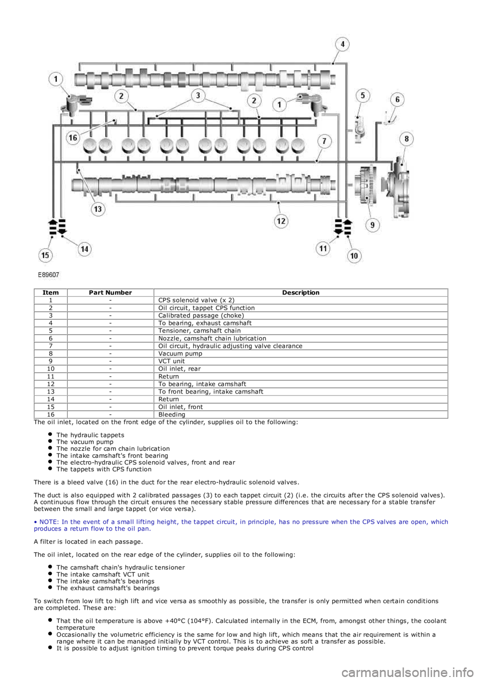
ItemPart NumberDescription1-CPS s olenoid valve (x 2)2-Oil circuit , t appet CPS funct ion3-Calibrated pass age (choke)4-To bearing, exhaus t cams haft5-Tensioner, cams haft chain6-Noz zle, cams haft chain lubricat ion7-Oil circuit , hydraulic adjus ting valve clearance8-Vacuum pump9-VCT unit10-Oil inlet , rear11-Ret urn12-To bearing, int ake cams haft13-To front bearing, intake camshaft14-Ret urn15-Oil inlet , front16-BleedingThe oil inlet , locat ed on the front edge of t he cylinder, s upplies oil t o t he following:
The hydraulic t appet sThe vacuum pumpThe noz zle for cam chain lubricat ionThe int ake cams haft 's front bearingThe electro-hydraulic CPS s olenoid valves , front and rearThe t appet s with CPS funct ion
There is a bleed valve (16) in t he duct for t he rear elect ro-hydraulic s olenoid valves .
The duct is als o equipped wit h 2 calibrat ed pas sages (3) t o each tappet circuit (2) (i.e. the circuits aft er t he CPS s olenoid valves ).A cont inuous flow through t he circuit ens ures t he neces s ary s t able pres sure differences that are neces s ary for a st able trans ferbet ween the s mall and large t appet (or vice vers a).
• NOTE: In t he event of a s mall lifting height , the t appet circuit , in principle, has no pres s ure when the CPS valves are open, whichproduces a ret urn flow t o t he oil pan.
A filt er is locat ed in each pass age.
The oil inlet , locat ed on the rear edge of t he cylinder, s upplies oil t o the following:
The camshaft chain's hydraulic t ens ionerThe int ake cams haft VCT unitThe int ake cams haft 's bearingsThe exhaus t cams haft's bearings
To switch from low lift t o high lift and vice vers a as s moot hly as pos sible, t he trans fer is only permitt ed when cert ain condit ionsare complet ed. Thes e are:
That the oil t emperature is above +40°C (104°F). Calculat ed int ernally in the ECM, from, amongst ot her t hings , t he coolantt emperatureO ccasionally t he volumetric efficiency is t he s ame for low and high lift , which means t hat the air requirement is wit hin arange where it can be managed init ially by VCT cont rol. This is t o achieve as soft a trans fer as pos sible.It is pos sible t o adjust ignition t iming t o prevent t orque peaks during CPS cont rol
Page 626 of 3229
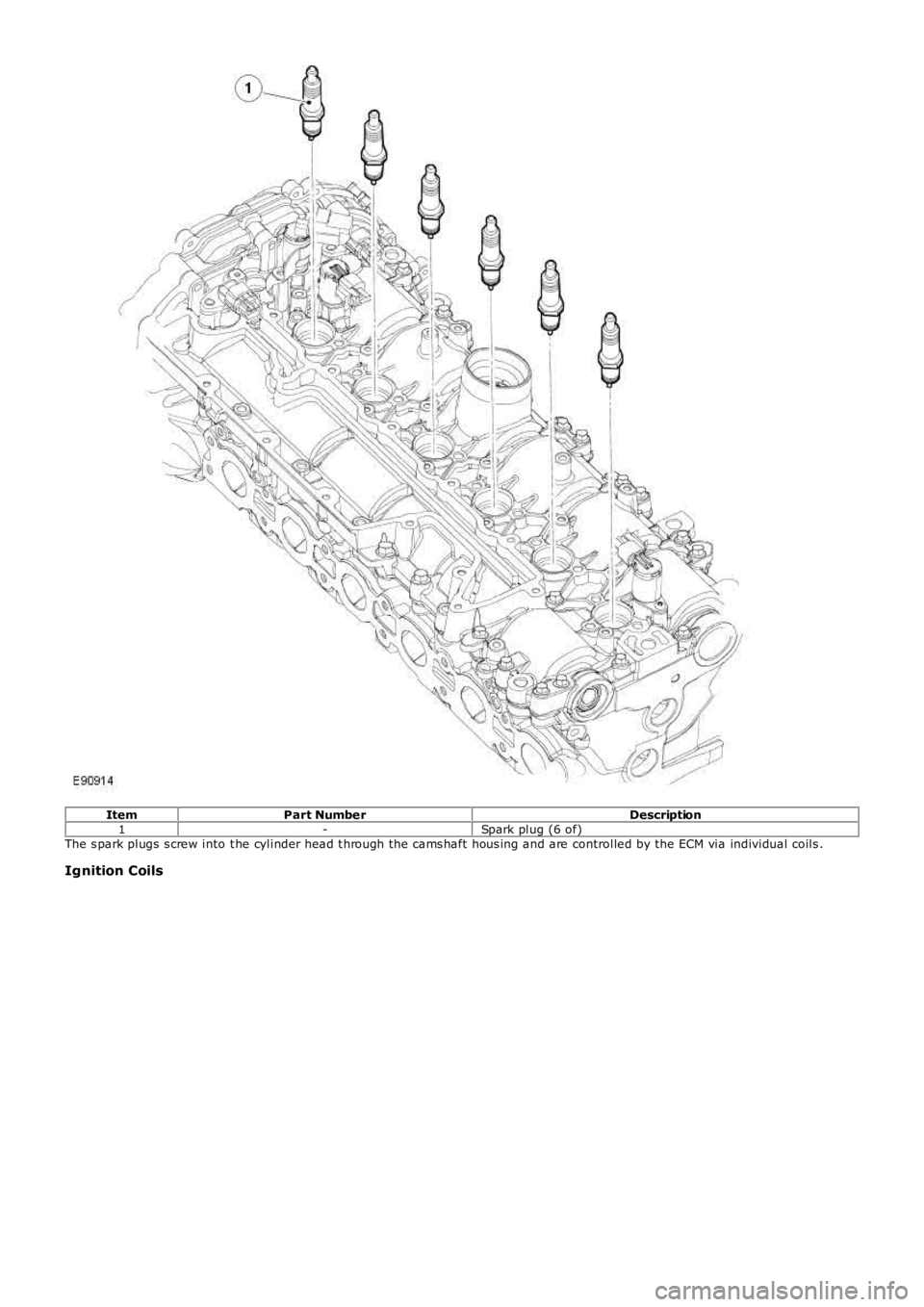
ItemPart NumberDescription1-Spark plug (6 of)The s park plugs s crew into t he cylinder head t hrough the cams haft hous ing and are controlled by the ECM via individual coils .
Ignition Coils
Page 627 of 3229
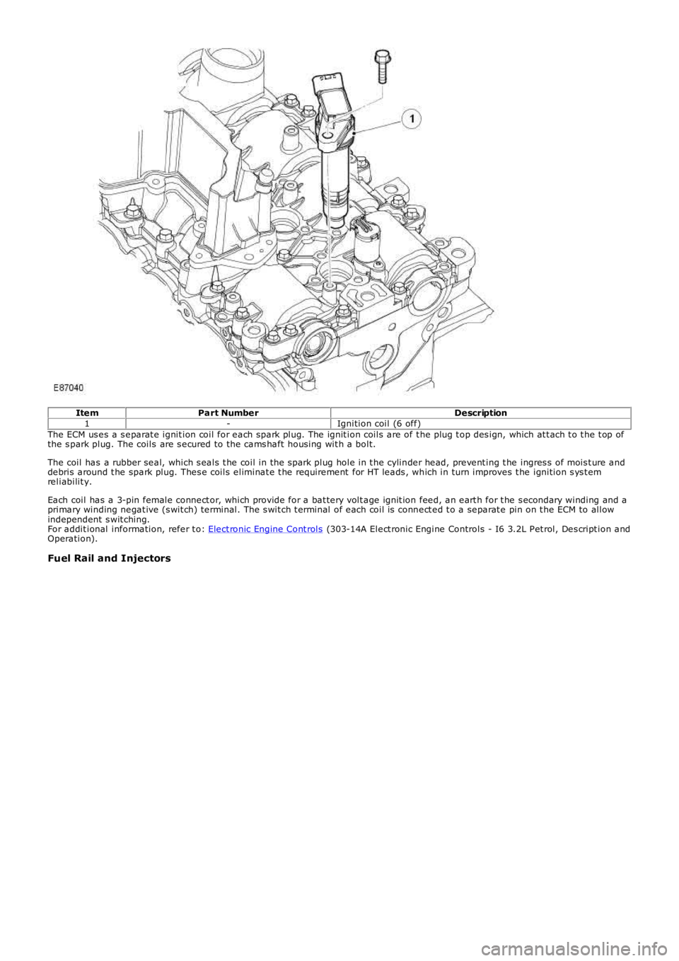
ItemPart NumberDescription1-Ignition coil (6 off)The ECM us es a s eparat e ignit ion coil for each spark plug. The ignit ion coils are of t he plug t op des ign, which at t ach t o t he t op ofthe s park plug. The coils are s ecured to the cams haft hous ing wit h a bolt.
The coil has a rubber seal, which s eals t he coil in the s park plug hole in t he cylinder head, prevent ing t he ingres s of mois t ure anddebris around t he spark plug. Thes e coils eliminat e t he requirement for HT leads , which in turn improves t he ignition s ys t emreliabilit y.
Each coil has a 3-pin female connect or, which provide for a bat tery volt age ignit ion feed, an eart h for t he s econdary winding and aprimary winding negat ive (s wit ch) terminal. The s wit ch t erminal of each coil is connect ed t o a separat e pin on t he ECM to allowindependent s wit ching.For addit ional information, refer t o: Elect ronic Engine Cont rols (303-14A Elect ronic Engine Controls - I6 3.2L Pet rol, Des cript ion andOperation).
Fuel Rail and Injectors
Page 650 of 3229
correct ly.
8. W ORN VALVE GUIDES: W hen t he needl e os ci ll at es over about a 13 kPa (4 i n-Hg) range at i dle s peed, t he valveguides could be worn. As engine s peed increas es , t he needl e wil l become st eady if guides are res pons ibl e.8.
9. W EAK VALVE SPRINGS: W hen the needle os cil lati on becomes more vi ol ent as engi ne RPM is increas ed, weakvalve s prings are indicated. The reading at i dle could be relat ively s t eady.9.
10. LATE VALVE TIMING: A s teady but low reading could be caus ed by lat e valve t imi ng.10.
11. IGNITION TIMING RETARDED: Retarded i gnit ion t imi ng wil l produce a s teady but s omewhat l ow readi ng.11.
12. INSUFFICIENT SPARK PLUG GAP: W hen s park pl ugs are gapped too clos e, a regul ar, s mall puls ati on of theneedle can occur.12.
13. INTAKE LEAK: A l ow, st eady reading can be caused by an int ake mani fol d or throt t le body gas ket l eak.13.
14. BLOW N HEAD GASKET: A regul ar drop of fai r magnit ude can be caus ed by a blown head gas ket or warpedcyli nder head t o cyl inder bl ock surface.14.
15. RESTRICTED EXHAUST SY STEM: W hen t he engine i s fi rs t s tarted and is i dl ed, the readi ng may be normal, butas t he engine RPM is i ncreas ed, the back pres s ure caus ed by a clogged muffler, ki nked tail pi pe or ot her concernswi ll cause the needle t o s l owl y drop to 0 kPa (0 in-Hg). The needl e t hen may s lowly ri se. Exces s ive exhaus tclogging will cause the needle to drop t o a l ow point even if t he engine i s onl y i dling.
15.
W hen vacuum leaks are indicated, s earch out and correct the caus e. Excess ai r leaking i nt o t he s yst em will ups et the fuelmi xt ure and caus e concerns s uch as rough i dle, mi ss i ng on accelerat ion or burned valves . If the l eak exi st s i n an acces s orys uch as the power brake boost er, t he unit wi ll not functi on correctl y. Always repair vacuum leaks .
Page 1111 of 3229
Publi s hed: 11-May-2011
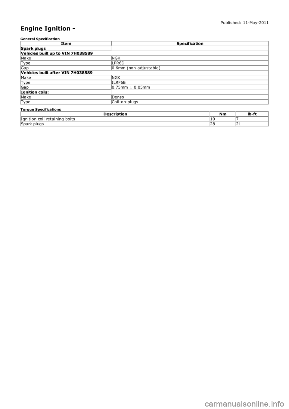
Engine Ignition -
General SpecificationItemSpecification
Spark plugs
Vehicles built up to VIN 7H038589MakeNGK
TypeLPR6D
Gap0.6mm (non-adjust able)Vehicles built after VIN 7H038589
MakeNGK
TypeILRF6BGap0.75mm ± 0.05mm
Ignition coils:
MakeDensoTypeCoil-on-pl ugs
Torque SpecificationsDescriptionNmlb-ft
Igni ti on coi l ret aining bolt s107
Spark pl ugs2821
Page 1112 of 3229
Publi s hed: 11-May-2011
Engine Ignition - Engine Ignition
Des cript ion and Operat ion
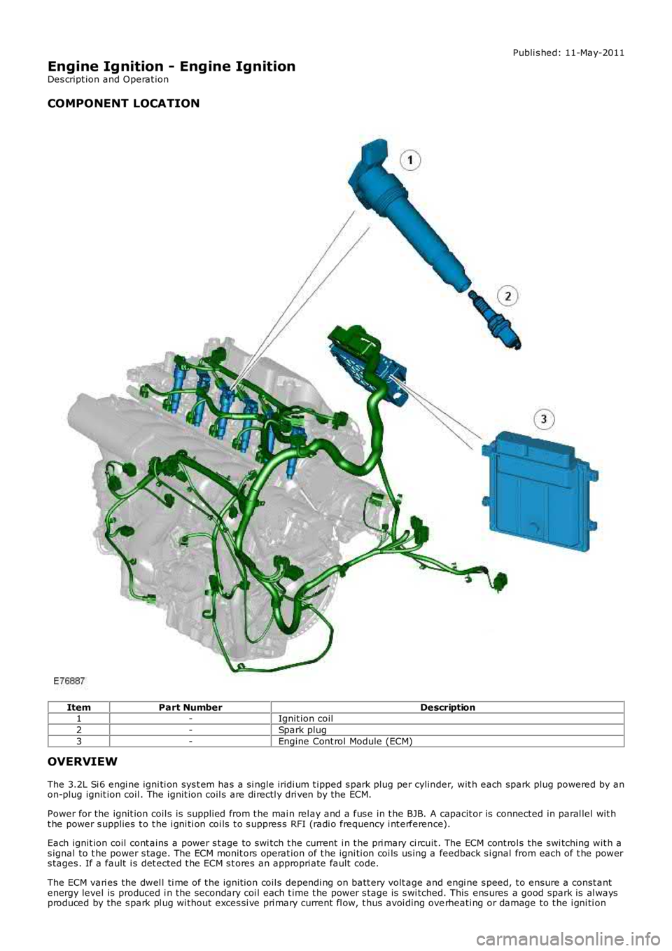
COMPONENT LOCATION
ItemPart NumberDescription1-Ignit ion coil
2-Spark plug
3-Engine Cont rol Module (ECM)
OVERVIEW
The 3.2L Si 6 engi ne igni ti on sys t em has a s i ngl e iridi um t ipped s park plug per cylinder, wit h each spark plug powered by anon-plug ignit ion coil . The ignit ion coil s are di rectl y dri ven by the ECM.
Power for the ignit ion coil s is suppli ed from t he mai n rel ay and a fus e in t he BJB. A capacit or is connected in paral lel wit ht he power s upplies t o t he i gni ti on coi ls t o s uppres s RFI (radi o frequency i nt erference).
Each ignit ion coil cont ains a power s t age to swi tch t he current i n t he pri mary ci rcuit . The ECM cont rol s the swi tching wit h as ignal to t he power s tage. The ECM monit ors operat ion of t he igni ti on coi ls us ing a feedback s i gnal from each of t he powers tages . If a fault i s det ected t he ECM s t ores an appropri ate fault code.
The ECM vari es the dwel l ti me of t he ignit ion coil s dependi ng on batt ery volt age and engi ne s peed, t o ensure a const antenergy level is produced i n the secondary coi l each t ime t he power s t age is s wi tched. This ens ures a good spark is al waysproduced by the s park pl ug wi thout exces si ve pri mary current fl ow, t hus avoi ding overheati ng or damage to t he i gni ti on