gas type LAND ROVER FRELANDER 2 2006 Repair Manual
[x] Cancel search | Manufacturer: LAND ROVER, Model Year: 2006, Model line: FRELANDER 2, Model: LAND ROVER FRELANDER 2 2006Pages: 3229, PDF Size: 78.5 MB
Page 22 of 3229
Do not t ouch t he glas s port ion of t he bulb.On no account s hould headlamps be s wi tched on wi th t he bulb removed from the headlamp.Bulb t es ti ng may only be carri ed out wit h the bul b ins t al led i n t he headl amp.Bulbs mus t be di spos ed of in accordance wit h the local aut horit y bye-laws .
Connectors and harnesses
The engi ne compart ment of a vehi cl e is a part icularl y host il e environment for el ect ri cal component s and connectors. Al waysobserve the foll owing:
Make s ure el ect ri cal ly related it ems are dry and oil free before di sconnect ing/connecti ng t es t equipment .Make s ure t hat dis connect ed mul ti pl ugs and s ens ors are prot ect ed from any pos s ibl e oil , coolant or other li qui dcont aminat ion. Any such contami nat ion could impair performance or l ead to component fail ure.Never force connectors apart or pull on t he wiring harnes s .Always make s ure locki ng t abs are dis engaged before di sconnect ing mul ti plugs etc. and make s ure that correctori ent ati on is achieved before connecti on.Make s ure t hat any protecti on covers, i nsul at ion et c. are replaced if dis t urbed.
Having confirmed t hat a component is fault y, carry out t he fol lowing:
Swit ch off t he ignit ion and di s connect t he batt ery.Remove the component and support t he dis connected harnes s .W hen replaci ng electrical components , keep oily hands away from electrical connect ions and make s ure that lockingt abs on connect ors are ful ly engaged.
Battery Disconnection/Connection
Always refer to the El ect ri cal Secti on of this manual - Bat tery Connecti on/Dis connecti on pri or t o at tempt ing t o connect ordis connect the bat tery.For addit ional informat ion, refer t o: Specificati ons (414-01 Bat t ery, Mount ing and Cables , Speci ficat ions).
Fuel Handling Precautions
The fol lowing informati on li s ts bas ic precauti ons which mus t be obs erved if fuel i s t o be handl ed s afely. It als o outl inesother areas of ris k which mus t not be i gnored. As t his informati on is is sued for basi c gui dance only, consul t your local Fi reDepart ment where any doubt as to personal and envi ronmental s afet y exi s ts - See al so Heal th and Safety Precaut ions .
General precaut ions
Always have t he correct type of fire ext inguis her cont aining Foam, CO2, Gas or powder acces s ible when handl ing ordrai ni ng fuel or dis mantl ing fuel s ys tems . Fire exti ngui shers mus t als o be l ocat ed in areas where fuel i s s tored.
Make s ure t hat sui table warning si gns are exhibit ed.
Keep all s ources of ignit ion wel l away from areas where fuel is bei ng handl ed.
Make s ure t hat any leadlamps are fl ameproof and kept clear of spi ll age.
• W ARNINGS:
Do not di sas s emble or reas s emble fuel sys tem components whils t vehicle is over a pit .
No one should be permi tt ed to repair component s as sociat ed wit h fuel wi thout fi rs t having s peci alis t t rai ni ng.
Always dis connect t he vehi cl e batt ery before carryi ng out dis ass embly, reas s embly or drai ning work on a fuel sys tem.
Fuel t ank and s ys t em drai ning
Drai ning mus t be carried out in accordance wit h t he procedures given in the relevant Fuel Syst em s ecti on of thi s manual .
• W ARNINGS:
Never drain fuel or work on a fuel sys t em whil e t he vehi cl e i s over a pi t. Ext raction or draining of fuel must becarri ed out in a well venti lated area.
Al ways at tach fuel vapor warning l abel s t o fuel t anks i mmediat ely after drai ni ng.
Contai ners us ed for s toring fuel must be cl early marked wit h t he cont ents and pl aced i n a safe s torage area whichmeets the requi rement s of the local authorit y.
CAUTION: Some fuel l ines are now i ns t alled wit h 'quick release' connectors. If a connect or i s damaged, no at t emptmus t be made t o repai r the connect or, a new fuel line and connect or(s ) as s embly must be ins tall ed.
Always release pipe cli ps full y before att empti ng t o dis connect fuel pipes.
Fuel tank repairs
CAUTION: No at tempt s hould be made to repair a pl ast ic fuel tank. If t he s truct ure of t he t ank is damaged, a new
Page 39 of 3229
Health Protection Precautions
Avoi d prol onged and repeat ed cont act wit h oil s, parti cularly us ed engine oi ls .W ear prot ect ive clot hing, including i mpervious gl oves where practi cable.Do not put oily rags i nt o pocket s .Avoi d contami nat ing cl ot hes, parti cularly underpants , wi th oi l.Heavi ly s oil ed clot hi ng and oil -i mpregnated foot wear s hould not be worn. Overall s mus t be cleaned regularly.First Ai d t reatment s hould be obt ained i mmediat el y for open cuts and wounds .Us e barrier creams , appl yi ng t hem before each work peri od, t o help the removal of oil from t he s ki n.W as h wi th soap and wat er to make s ure al l oi l is removed (s kin cl eans ers and nail brushes wi ll help). Preparati onscont aining lanol ine replace the nat ural s ki n oil s which have been removed.Do not us e gasol ine (pet rol ), keros ene (paraffin), di esel fuel (gas oi l), thi nners or s ol vent s for cleaning skin.If skin dis orders develop, obtain medical advice wi thout delay.W here practi cable, degreas e component s pri or t o handling.W here there is a ri s k of eye cont act , eye protecti on s houl d be worn, for exampl e chemical goggles or face s hiel ds ;in addi ti on an eye was h facil it y s houl d be provided.
Environmental Precautions
This s ecti on provides general informati on which can help t o reduce t he environment al i mpact s from the act ivit ies carriedout in workshops .
Emis s ions t o air
Many of the act ivit ies t hat are carried out i n works hops emit gas es and fumes whi ch can contribut e to global warmi ng,depl eti on of the ozone layer and/or the format ion of phot ochemical s mog at ground level. By cons ideri ng how t he works hopact ivi ti es are carried out , thes e gases and fumes can be mi nimi s ed, t hus reduci ng t he impact on t he envi ronment.
Exhaus t fumes
Runni ng car engines i s an es sent ial part of works hop act ivi ti es and exhaust fumes need t o be venti lated to at mos phere.However, the amount of t ime engi nes are runni ng and the pos it ion of t he vehi cle s hould be carefully cons idered at al lt imes , to reduce the releas e of poi s onous gas es and mini mis e t he i nconveni ence t o peopl e l iving nearby.
Solvent s
Some of t he cl eani ng agent s us ed are sol vent based and wil l evaporate rapidl y to atmos phere i f used carel ess l y, or i fcont ainers are l eft unseal ed. Al l contai ners mus t be firmly cl os ed when not requi red and s olvent should be used sparingly.W herever poss i bl e, sol vent s havi ng a l ow t oxi ci ty and flammabi li ty should be sel ect ed. Al ways foll ow t he ins t ructi onss uppl ied by t he s olvent manufact urer. Si mil arl y, many pai nt s are s olvent bas ed and the s pray s houl d be us ed in such away as t o reduce emi ss i ons t o a mini mum.
Refrigerant
It is i ll egal t o rel eas e any refrigerant int o t he atmos phere. Dis charge and repl acement of thes e mat eri al s from aircondi ti oni ng uni ts should onl y be carried out us ing t he appropri at e equipment .
Dis charges to water
Mos t works hops wi ll have t wo s ys t ems for di schargi ng wast e wat er - st orm drai ns and foul drains . Storm drains s houl d onlyreceive clean wat er i.e. rainwat er. Foul drai ns wil l accept many of the normal was t e wat er i .e. was hing wat er, detergent sand domest ic type was te BUT NOT oi l, petrol, s olvent , acids , hydraul ic fluid, anti freeze and si mil ar fl ui ds. If in doubt ,always cons ult the l ocal authori ty or wat er company.
Spill ages
Every precauti on mus t be taken t o prevent s pi ll age of oi l, fuel , sol vent s etc., reachi ng the drains . All handl ing of s uchmat erial s mus t take pl ace wel l away from drai ns and preferably i n an area wit h a s uit able contai ni ng wall t o preventdis charge int o drai ns or watercours es . If a spi llage occurs , it mus t be s oaked up immedi ately us i ng a s pil l ki t whereprovided.
Checkli s t
Spillage prevention:
Store li quids in a s ecure area.
Make s ure t hat taps on l iquid cont ai ners are s ecure and cannot be acci dent ally turned on.
Prot ect bulk st orage t anks from vandal is m by locki ng the val ves .
Trans fer li quids from one cont ai ner t o another i n an area away from open drai ns .
Ensure li ds are replaced s ecurel y on cont ainers .
Have s pi ll kit s availabl e near t o point s of s torage and liquid handl ing areas .
Spill Ki ts
Speci al mat eri als are avai lable to abs orb a number of di fferent subs tances. They can be in granular form, ready t o us e andare suppli ed in sui table cont ai ners . Dis posal of used spi ll absorbing mat eri al i s deal t wit h i n W as t e management .
Land contamination
Oil s , fuels and s olvents etc. can cont aminate any soi l wit h which t hey come int o cont act . Such materials MUST never bedis posed of by pouri ng on t o s oil and every precauti on mus t be t aken t o avoid s pil lage reaching s oil . W as te materials
Page 41 of 3229
Some operat ions may produce high noi se levels whi ch could, i n ti me, damage hearing. In thes e cases , s uit abl e earprot ect ion mus t be worn.
Solder
Solders are mi xtures of met als such t hat t he mel ti ng point of the mixture i s bel ow that of t he const it uent metals (normal lylead and t in). Sol der appli cat ion does not normal ly gi ve ri se to toxic l ead fumes , provided a gas /ai r fl ame i s used.Oxy-acet ylene flames s hould not be us ed, as they are much hot t er and will cause lead fumes to be produced.
Some fumes may be produced by t he appl icati on of any fl ame t o s urfaces coat ed wi th grease, and i nhalat ion of t heses houl d be avoided.
Removal of exces s s older s houl d be undertaken wi th care, t o make sure t hat fine l ead dus t i s not produced, which can givet oxi c effect s if i nhal ed. Res pirat ory protecti on may be necess ary.
Solder spi ll age and fil ings s houl d be coll ect ed and removed promptl y to prevent general air contami nat ion by lead.
High st andards of pers onal hygi ene are necess ary in order t o avoid inges t ion of l ead or i nhal ati on of sol der dus t fromclothi ng.
Solvents
For example acet one, whi te s pirit , t ol uene, xylene, trichloroet hane.
Us ed in cl eani ng and dewaxi ng materials , paint s, pl as t ics , res ins and t hinners .
Some may be highly flammabl e or fl ammable.
Skin contact wil l degreas e t he s kin and may res ult i n irri tat ion and dermati ti s fol lowing repeat ed or prolonged cont act.Some can be abs orbed t hrough the s kin in t oxic or harmful quant it ies .
Splas hes in t he eye may cause severe irri tat ion and coul d l ead to los s of vi s ion.
Bri ef expos ure of high concent rat ions of vapors or mis t s wil l caus e eye and t hroat irri tat ion, drows ines s, di zzines s ,headaches and, i n t he wors t circums t ances , unconscious nes s .
Repeat ed or prolonged expos ure to excess i ve but l ower concent rat ions of vapors or mis t s , for which t here might not beadequat e warni ng indicati ons , can caus e more s eri ous toxic or harmful effect s .
As pi rat ion i nto the l ungs , for example through vomi ti ng, i s the most serious cons equence of s wall owi ng.
Avoi d s plas hes to the s kin, eyes and cl othi ng. W ear prot ecti ve gl oves , goggl es and clothi ng if neces s ary.
Make s ure t here i s good vent il ati on when in us e, avoi d breat hing fumes, vapors and spray mis t s and keep contai nerst ightl y s eal ed. Do not us e i n confined s paces .
W hen s praying materials contai ning s olvents , for example pai nt s , adhes ives , and metal coat ings , use ext racti onvent il ati on or pers onal res piratory prot ect ion i n t he abs ence of adequate general venti lati on.
Do not apply heat or fl ame except under s peci fi c and detail ed manufacturers i ns t ructi ons .
Suspended Loads
CAUTION: Never improvi se lift ing t ackle.
There i s always a danger when loads are lifted or s us pended. Never work under an unsupported, s us pended or rais ed l oad,for example a s us pended engi ne.
Always make s ure that l ift ing equi pment s uch as jacks , hoi st s , axl e s tands and s li ngs are adequat e and s uit abl e for thejob, i n good condit ion and regul arl y maint ained.
Viton
In common wi th many ot her manufact urers vehi cl es, s ome components i nst all ed to Land Rover vehi cl es have seals , 'O 'ri ngs or gas kets whi ch cont ain a material known as 'Vit on'.
Vit on is a fluoroelas tomer, that i s a s ynt heti c rubber type whi ch contai ns Fluori ne. Al though Vit on is the mos t wel l knownfl uoroelas tomer, there are ot hers , including Fl uorel and Tecmofl on.
W hen us ed under des ign condit ions fl uoroelas tomers are perfectl y s afe. If, however, they are expos ed t o t emperatures inexces s of 400°C, t he material wil l not burn, but wi ll decompos e, and one of the products formed is hydrofluori c acid.
This acid is extremely corros ive and may be abs orbed di rectl y, t hrough cont act , int o t he general body s ys tem. WHERECASES OF SKIN CONT ACT OCCUR, SEEK IMMEDIAT E MEDICAL HELP.
O-ri ngs , s eal s or gaskets which have been expos ed to very high t emperat ures wi ll appear charred or as a black s ti ckys ubs t ance.
DO NOT, under any ci rcums tances touch t hem or the at t ached component s.
Enqui ri es should be made t o determine whet her Vi ton or any ot her fluoroel as t omer has been us ed i n the affect ed O-ring,s eal or gas ket . If t hey are of nat ural rubber or ni trile there is no hazard. If in doubt , be caut ious as t he material may beVit on or any fl uoroelas tomer.
If Vi ton or any ot her fluoroel as t omers have been us ed, t he affect ed area should be decontami nated before t he
Page 96 of 3229
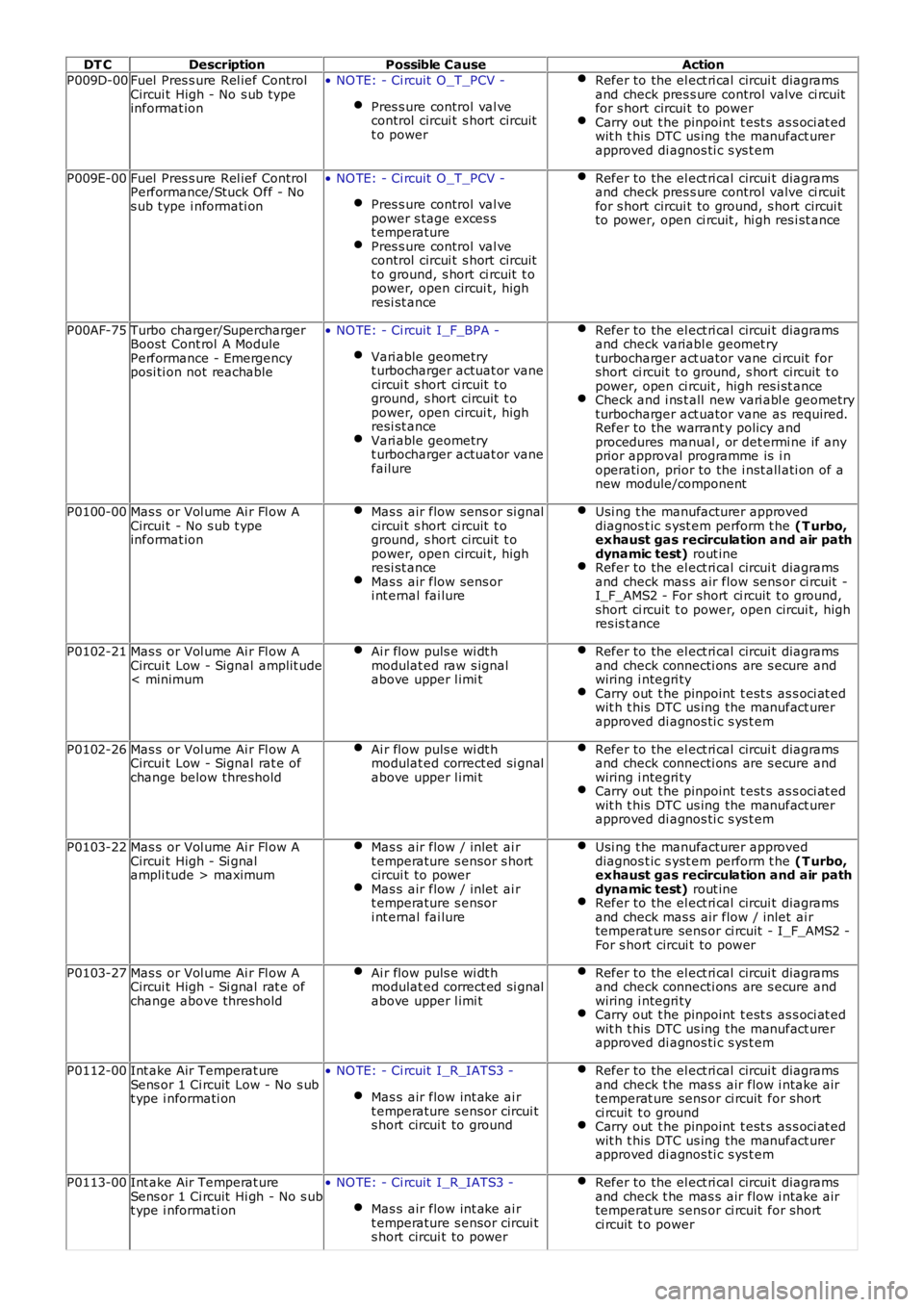
DT CDescriptionPossible CauseAction
P009D-00Fuel Pres s ure Rel ief ControlCircui t High - No s ub typeinformat ion
• NO TE: - Ci rcuit O_T_PCV -
Pres s ure control val vecontrol circui t s hort circuitt o power
Refer to the el ect ri cal circui t diagramsand check pres s ure control valve ci rcuitfor s hort circui t to powerCarry out t he pinpoint t est s as s oci at edwit h t his DTC us ing the manufact urerapproved di agnos ti c s ys t em
P009E-00Fuel Pres s ure Rel ief ControlPerformance/Stuck Off - Nos ub type i nformati on
• NO TE: - Ci rcuit O_T_PCV -
Pres s ure control val vepower s tage exces st emperaturePres s ure control val vecontrol circui t s hort circuitt o ground, s hort ci rcuit t opower, open circui t, highresi st ance
Refer to the el ect ri cal circui t diagramsand check pres s ure control valve ci rcuitfor s hort circui t to ground, s hort circui tto power, open ci rcuit , hi gh res i st ance
P00AF-75Turbo charger/SuperchargerBoost Cont rol A ModulePerformance - Emergencyposi ti on not reachable
• NO TE: - Ci rcuit I_F_BPA -
Vari able geometryt urbocharger actuat or vanecircui t s hort ci rcuit t oground, s hort circuit t opower, open circui t, highresi st anceVari able geometryt urbocharger actuat or vanefailure
Refer to the el ect ri cal circui t diagramsand check variabl e geomet ryturbocharger act uator vane ci rcuit forshort ci rcuit t o ground, s hort circuit t opower, open ci rcuit , high res i st anceCheck and i ns t all new vari abl e geometryturbocharger act uator vane as required.Refer to the warrant y policy andprocedures manual , or det ermi ne if anyprior approval programme is i noperati on, prior to the i nst all ati on of anew module/component
P0100-00Mas s or Vol ume Ai r Fl ow ACircui t - No s ub t ypeinformat ion
Mas s air flow sens or si gnalcircui t s hort ci rcuit t oground, s hort circuit t opower, open circui t, highresi st anceMas s air flow sens ori nt ernal fai lure
Usi ng t he manufacturer approveddiagnos t ic s yst em perform t he (T urbo,exhaust gas recirculation and air pathdynamic test) rout ineRefer to the el ect ri cal circui t diagramsand check mas s air flow sens or ci rcuit -I_F_AMS2 - For short ci rcuit t o ground,short ci rcuit t o power, open circui t, highres is t ance
P0102-21Mas s or Vol ume Ai r Fl ow ACircui t Low - Signal amplit ude< minimum
Ai r flow puls e wi dt hmodulat ed raw s ignalabove upper l imi t
Refer to the el ect ri cal circui t diagramsand check connecti ons are s ecure andwiring i ntegri tyCarry out t he pinpoint t est s as s oci at edwit h t his DTC us ing the manufact urerapproved di agnos ti c s ys t em
P0102-26Mas s or Vol ume Ai r Fl ow ACircui t Low - Signal rat e ofchange below threshold
Ai r flow puls e wi dt hmodulat ed correct ed si gnalabove upper l imi t
Refer to the el ect ri cal circui t diagramsand check connecti ons are s ecure andwiring i ntegri tyCarry out t he pinpoint t est s as s oci at edwit h t his DTC us ing the manufact urerapproved di agnos ti c s ys t em
P0103-22Mas s or Vol ume Ai r Fl ow ACircui t High - Si gnalampli tude > maximum
Mas s air flow / inlet ai rt emperature s ensor s hortcircui t to powerMas s air flow / inlet ai rt emperature s ensori nt ernal fai lure
Usi ng t he manufacturer approveddiagnos t ic s yst em perform t he (T urbo,exhaust gas recirculation and air pathdynamic test) rout ineRefer to the el ect ri cal circui t diagramsand check mas s air flow / inlet ai rtemperat ure sens or ci rcuit - I_F_AMS2 -For s hort circui t to power
P0103-27Mas s or Vol ume Ai r Fl ow ACircui t High - Si gnal rat e ofchange above threshold
Ai r flow puls e wi dt hmodulat ed correct ed si gnalabove upper l imi t
Refer to the el ect ri cal circui t diagramsand check connecti ons are s ecure andwiring i ntegri tyCarry out t he pinpoint t est s as s oci at edwit h t his DTC us ing the manufact urerapproved di agnos ti c s ys t em
P0112-00Int ake Air Temperat ureSens or 1 Ci rcuit Low - No s ubt ype i nformati on
• NO TE: - Ci rcuit I_R_IATS3 -
Mas s air flow int ake ai rt emperature s ensor circui ts hort circui t to ground
Refer to the el ect ri cal circui t diagramsand check t he mas s air flow i ntake airtemperat ure sens or ci rcuit for shortci rcuit t o groundCarry out t he pinpoint t est s as s oci at edwit h t his DTC us ing the manufact urerapproved di agnos ti c s ys t em
P0113-00Int ake Air Temperat ureSens or 1 Ci rcuit Hi gh - No s ubt ype i nformati on
• NO TE: - Ci rcuit I_R_IATS3 -
Mas s air flow int ake ai rt emperature s ensor circui ts hort circui t to power
Refer to the el ect ri cal circui t diagramsand check t he mas s air flow i ntake airtemperat ure sens or ci rcuit for shortci rcuit t o power
Page 416 of 3229
brake boos ter.
5. Operate the engine for a minimum of 10 s econds at a fast i dle. Stop the engine and al low t he vehicle t o s t andfor 10 mi nut es. Then, appl y the brake pedal wi th approxi mately 89 N (20lb) of force. The pedal feel (brakeappli cat ion) s houl d be t he s ame as t hat not ed wit h t he engine runni ng. If the brake pedal feel s hard (no poweras s is t), ins t al l a new valve and t hen repeat t he tes t. If t he brake pedal s t ill feels hard, i ns t all a new brakeboos ter. If t he brake pedal movement feel s s pongy, bleed t he brake s ys t em.REFER t o: Brake Syst em Bl eedi ng (206-00 Brake Syst em - General Informati on, General Procedures ) /Brake Sys t em Pres s ure Bl eedi ng (206-00 Brake Syst em - General Informati on, General Procedures ).
5.
Brake Master Cylinder
Us ual ly, t he fi rs t and s tronges t indicat or of anything wrong i n t he brake s ys t em i s a feeling through t he brake pedal. Indiagnosi ng the condit ion of t he brake mas t er cyli nder, check pedal feel as evidence of a brake concern. Check for brakewarni ng lamp ill uminat ion and t he brake fluid level i n t he brake mas t er cyli nder reservoi r.
Normal Condit ions
The fol lowing condit ions are cons idered normal and are not i ndi cat ions t hat t he brake mast er cyl inder i s i n need of repair.
Modern brake sys tems are des igned t o produce a pedal effort that is not as hard as in the pas t . Compl aint s of lightpedal effort s s houl d be compared t o t he pedal efforts of another vehi cl e of t he s ame model and year.The fl uid l evel wi ll fal l wit h brake pad wear.
Abnormal Condi ti ons
Changes i n t he brake pedal feel or brake pedal travel are indicators t hat s omet hi ng coul d be wrong in the brake sys tem.The diagnost ic procedure and techni ques us e brake pedal feel , warning i ndi cat or il lumi nat ion and l ow brake flui d level asindicat ors t o diagnosi ng brake s yst em concerns . The foll owing condi ti ons are consi dered abnormal and indi cat e t hat t hebrake mas t er cyli nder i s in need of repai r:
• NOTE: Pri or to carrying out any diagnosi s , ens ure the brake sys tem warni ng indicator i s functi onal .
Brake pedal goes down fast . This could be caus ed by an external or int ernal leak.Brake pedal goes down s l owl y. Thi s coul d be caused by an int ernal or external l eak.Brake pedal is l ow or feels spongy. Thi s condit ion may be caus ed by no fl ui d i n the brake mas ter cylinder, reservoi rcap vent holes cl ogged or air i n t he hydraul ic s ys tem.Brake pedal effort is excess ive. This may be caus ed by a bi nd or obs t ructi on in the pedal/li nkage, a faul tynon-ret urn val ve, boost er or ins ufficient boos t er vacuum.Rear brakes lock up during light pedal force. Thi s may be caus ed by damaged brake pads , a parti ally appl ied parkingbrake, a damaged ABS s ens or or bearing fail ure.Brake pedal effort errat ic. This condit ion could be caus ed by the brake boos t er or incorrectl y ins tal led brake pads .Brake warning i ndi cat or is on. This may be caus ed by low fl uid l evel or fl oat as s embly damaged.
Non Pressure Leaks
Any reduced fl uid volume in t he brake mast er cyl inder res ervoi r may be caused by two types of none pres sure externalleaks .
Type 1: An ext ernal leak may occur at the brake mast er cyl inder res ervoir cap because of incorrect posi ti oning of t hegasket and cap. Repos it ion cap and gasket .
Type 2: An ext ernal leak may occur at the brake mast er cyl inder res ervoir mounti ng seal s. Repair s uch a l eak by ins tall ingnew s eals and make s ure that t he brake mas t er cyli nder reservoi r ret ai ning bolt i s correct ly i nst all ed.
Page 422 of 3229
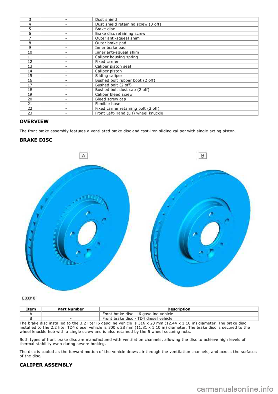
3-Dus t s hiel d
4-Dus t s hiel d ret aining s crew (3 off)
5-Brake dis c6-Brake dis c ret aini ng screw
7-Outer anti -s queal s him
8-Outer brake pad9-Inner brake pad
10-Inner ant i-s queal s him
11-Cal iper hous i ng spring12-Fi xed carri er
13-Cal iper pis ton seal
14-Cal iper pis ton15-Sl idi ng cal iper
16-Bus hed bolt rubber boot (2 off)
17-Bus hed bolt (2 off)18-Bus hed bolt dus t cap (2 off)
19-Cal iper bleed s crew
20-Bleed s crew cap21-Fl exi ble hos e
22-Fi xed carri er retai ni ng bolt (2 off)
23-Front Left-Hand (LH) wheel knuckle
OVERVIEW
The front brake as sembl y feat ures a venti lat ed brake dis c and cast -iron sl idi ng cal iper wit h s ingle act ing pi st on.
BRAKE DISC
ItemPart NumberDescription
A-Front brake dis c - i 6 gas ol ine vehicleB-Front brake dis c - TD4 di esel vehicle
The brake dis c i nst all ed to the 3.2 l it er i 6 gas ol ine vehicle is 316 x 28 mm (12.44 x 1.10 i n) diameter. The brake dis cins t al led t o t he 2.2 li ter TD4 dies el vehi cl e is 300 x 28 mm (11.81 x 1.10 in) diamet er. The brake di sc is s ecured t o thewheel knuckl e hub wi th a s ingle s crew and is al so ret ai ned by t he 5 wheel securi ng nut s .
Both types of front brake dis c are manufact ured wi th vent il at ion channel s , al lowi ng the di s c to achieve hi gh levels oft hermal st abil it y even during s evere braki ng.
The dis c i s cool ed as the forward mot ion of t he vehi cl e draws air t hrough the venti lat ion channel s, and acros s t he s urfacesof the di s c.
CALIPER ASSEMBLY
Page 435 of 3229
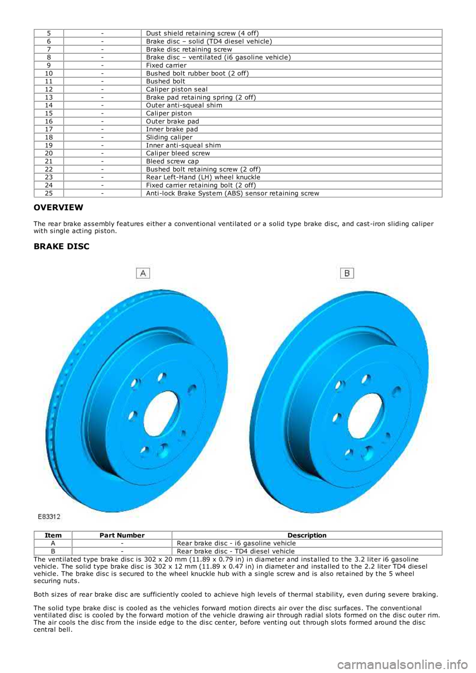
5
-Dus t s hi eld retai ni ng s crew (4 off)
6 -Brake di sc – s olid (TD4 di esel vehi cle)
7 -Brake di sc ret ai ning s crew
8 -Brake di sc – vent il ated (i6 gas oli ne vehi cl e)
9 -Fixed carrier
10 -Bus hed bol t rubber boot (2 off)
11 -Bus hed bol t
12 -Cali per pi st on s eal
13 -Brake pad retai ni ng s pri ng (2 off)
14 -Out er ant i-squeal shi m
15 -Cali per pi st on
16 -Out er brake pad
17 -Inner brake pad
18 -Sli ding cali per
19 -Inner anti -s queal s him
20 -Cali per bl eed screw
21 -Bleed s crew cap
22 -Bus hed bol t ret aining s crew (2 off)
23 -Rear Left-Hand (LH) wheel knuckle
24 -Fixed carrier ret aining bol t (2 off)
25 -Anti -l ock Brake Syst em (ABS) s ens or ret aining s crew
OVERVIEW
The rear brake as s embly feat ures ei ther a convent ional venti lat ed or a s olid type br ake di s c, and cast -iron sl idi ng cal iper
wit h s i ngl e act ing pi s ton.
BRAKE DISC Item
Part Number Description
A -Rear brake dis c - i 6 gas ol ine vehicle
B -Rear brake dis c - TD4 di esel vehicle
The vent il ated t ype brake dis c i s 302 x 20 mm (11.89 x 0.79 in) i n diamet er and ins t al led t o t he 3.2 l it er i6 gas oli ne
vehi cl e. The sol id t ype brake dis c i s 302 x 12 mm (11.89 x 0.47 i n) i n diamet er and ins tal led t o t he 2.2 lit er TD4 dies el
vehi cl e. The brake dis c i s s ecured to t he wheel knuckle hub wi th a s ingle screw and is al s o ret ained by t he 5 wheel
s ecuring nuts .
Both si zes of rear brake dis c are suffi ci ent ly cooled to achieve high level s of t her mal st abil it y, even duri ng s evere braking.
The s olid type brake di sc is cooled as t he vehi cles forward moti on direct s air over the di sc surfaces . The convent ional
vent il ated di sc is cooled by t he forward moti on of the vehicle drawing ai r through r adial s lots formed on t he dis c outer rim.
The air cools t he dis c from the i nsi de edge to the di s c cent er, before vent ing out t hrough s lots formed around t he dis c
cent ral bell .
Page 752 of 3229
Publi s hed: 11-May-2011
Engine - TD4 2.2L Diesel -
Lubricants, Fluids, Sealers and AdhesivesDescriptionDescription and part number.
‘T’ joi nts - ladder frame to engi ne blocks ealantThree bond TB 1215J
Oi l pan to bl ock s ealantThree bond TB 1215J
Cams haft l adder s eal antLocti te 518 (8510302)
Engine Oi lSAE 5W -30 oils conforming to Ford W SS-M2C13B specificat ion or ACEA A1 orB1
C apacities
ItemCapacity (liters/pints/US quarts)
Dry fi ll i ncludi ng fi lt er6.5/11.4/6.7Service fil l5.9/10.4/6.2
Amount of oil required t o bri ng level from t he lower t o t he upper mark on t he dips tick1.5/2.6/1.6
C ylinder Head Gasket Selection
Piston ProtusionT hickness of Compressed GasketNumber of holes at ' a'Number of holes at 'b'0.55 to 0.60 mm1.25 ± 0.04 mm11
0.61 to 0.65 mm1.30 ± 0.04 mm22
0.66 to 0.70 mm1.35 ± 0.04 mm330.71 to 0.75 mm1.40 ± 0.04 mm44
'a' and 'b' = Thi ckness identi fi cat ion
General Specification
ItemSpecificationType2.2 l it re, i nl ine 4, t urbocharged and int ercool ed dies el engine, t win overheadcamshaft , 4 valves per cyl inder
Cyli nder arrangementInl ine 4Cyli nder numberi ngNo.1 from gearbox end
Bore - nominal85.0 mm (3.346 i n)
St roke96.0 mm (3.779 i n)Capaci ty2179 cm³ (132.9 in³)
Firing order1 - 3 - 4 - 2
Compres s ion rati o16.6:1Di recti on of rotat ionClockwi s e viewed at FEAD
Maximum permi s sable cyl inder headwarp0.03mm (0.00118 i n)
Maximum pow er
All markets except Bel gi um118 kW (160 ps ) @ 4000rpmBelgi um s peci fi cat ion110 kW (150 ps ) @ 4000rpm
Maximum t orque400 Nm (295 l b-ft ) @ 2000rpm
Engine oil pressure*:At 1750 rev/min1.6 bar/160 kPa/23 l b/i n²
At 4000 rev/min3.1 bar/310 kPa/45 l b/i n²
Balance shaft to crankshaftclearance**:
Mi ni mum0.01mm
Maximum0.07mm* Prior to checking the engine oil pressure, a road test of 6 miles (10 kilometres) must be carried out. Do notattempt to attain normal engine operating temperature by allowing the engine to idle.
**If the backlash betw een the balance shaft and crankshaft is less than 0.01 mm or greater than 0.07 mm then thebalance shaft assembly must be replaced.
Torque SpecificationsDescriptionNmlb-ft
Acces s ory drive belt i dler bol t4835
Acces s ory drive belt t ensi oner bolt4835Camshaft pulley bolt
St age 12015
St age 260°60°Cams haft t imi ng belt cover bolt s65
Cams haft t imi ng chai n t ens ioner bolt s75
Crankshaft pulley bolt:St age 17052
St age 260°60°
Cranks haft rear s eal retai ner pl at e97Coolant outl et el bow97
Cyli nder head bolt sAA
Di ps t ick t ube bol t107Engine i ns ulat or lower11081
Engine i ns ulat or lower heat s hiel d107
Engine i ns ulat or lower li nk bracket s11081Engine i ns ulat or upper11081
Page 754 of 3229
Publi s hed: 11-May-2011
Engine - TD4 2.2L Diesel - Engine
Des cript ion and Operat ion
EXTERNAL VIEW
OVERVIEW
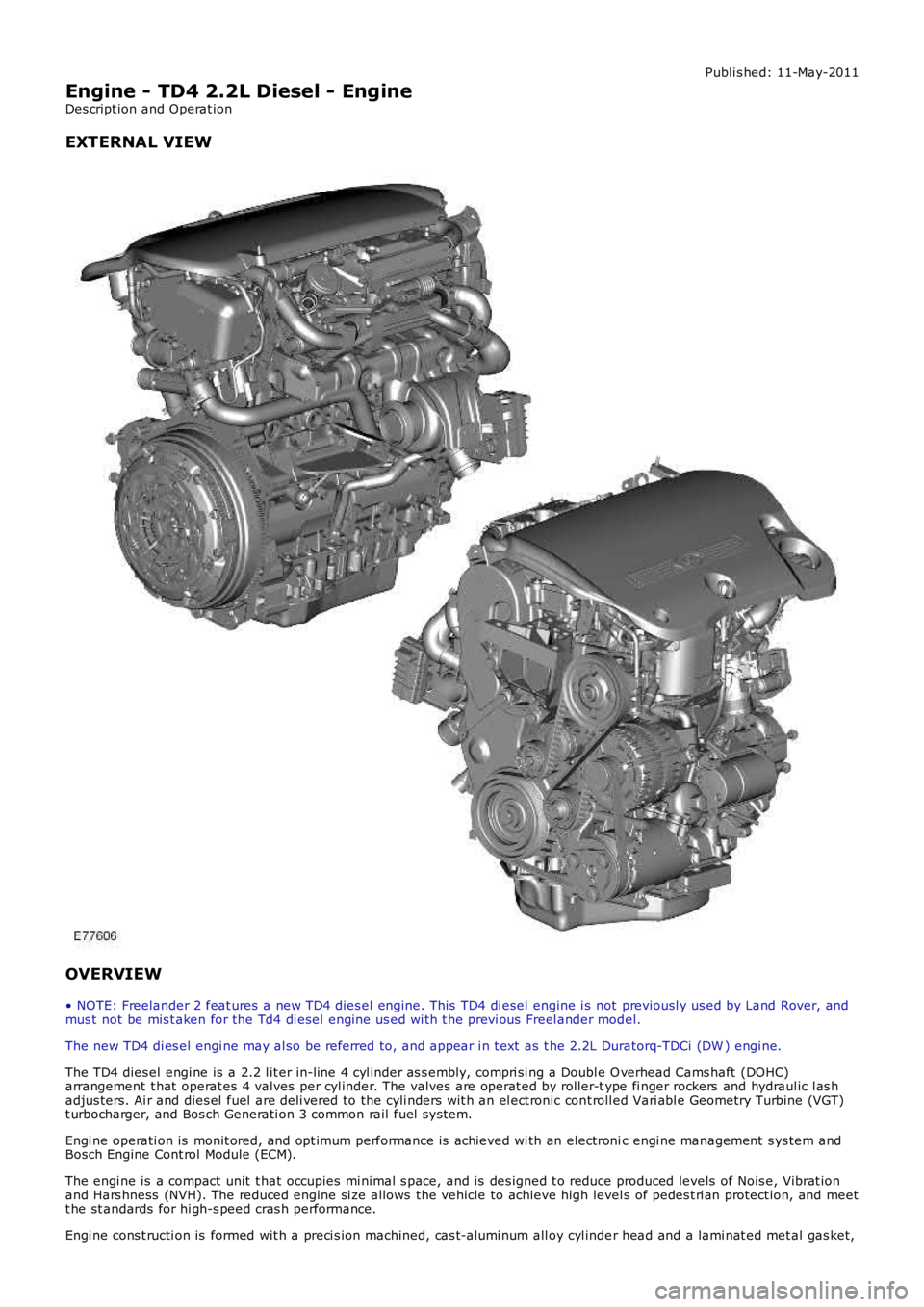
• NOTE: Freelander 2 feat ures a new TD4 dies el engine. This TD4 di esel engine i s not previousl y us ed by Land Rover, andmus t not be mis t aken for the Td4 di esel engine us ed wi th t he previ ous Freel ander model.
The new TD4 di es el engi ne may al so be referred to, and appear i n t ext as t he 2.2L Duratorq-TDCi (DW ) engi ne.
The TD4 dies el engi ne is a 2.2 l it er in-line 4 cyl inder as s embly, compri si ng a Double O verhead Cams haft (DOHC)arrangement t hat operat es 4 valves per cyl inder. The valves are operat ed by roller-type fi nger rockers and hydraul ic l as hadjus ters. Ai r and dies el fuel are deli vered to the cyli nders wit h an el ect ronic cont roll ed Vari abl e Geometry Turbine (VGT)t urbocharger, and Bos ch Generati on 3 common rail fuel s ys tem.
Engi ne operati on is monit ored, and opt imum performance is achieved wi th an electronic engi ne management s ys tem andBosch Engine Cont rol Module (ECM).
The engi ne is a compact unit t hat occupies mi nimal s pace, and is des igned t o reduce produced levels of Nois e, Vibrat ionand Hars hness (NVH). The reduced engine si ze allows the vehicle to achieve high level s of pedes t ri an protect ion, and meett he st andards for hi gh-s peed cras h performance.
Engi ne cons t ructi on is formed wit h a preci s ion machined, cas t-alumi num all oy cyl inder head and a lami nat ed met al gas ket,
Page 766 of 3229
ItemPart NumberDescription
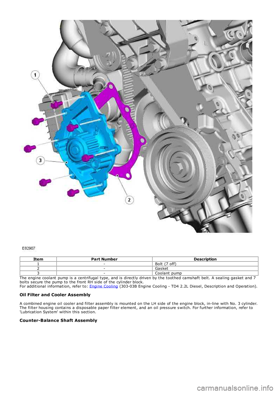
1-Bolt (7 off)2-Gas ket
3-Coolant pump
The engi ne cool ant pump is a cent ri fugal type, and is direct ly driven by t he t oot hed cams haft bel t. A s eal ing gas ket and 7bolt s s ecure the pump to the front RH si de of the cyli nder bl ock.For addit ional informat ion, refer t o: Engi ne Cooling (303-03B Engine Cooli ng - TD4 2.2L Dies el , Descripti on and Operat ion).
Oil Filter and Cooler Assembly
A combined engine oi l cooler and fil ter as sembl y is mount ed on t he LH s ide of t he engine block, in-line wit h No. 3 cylinder.The fi lt er hous ing contai ns a dis pos abl e paper fil ter element , and an oil pres s ure swi tch. For furt her i nformat ion, refer to'Lubri cat ion Sys tem' wi thin thi s s ect ion.
Counter-Balance Shaft Assembly