sport mode LAND ROVER FRELANDER 2 2006 Repair Manual
[x] Cancel search | Manufacturer: LAND ROVER, Model Year: 2006, Model line: FRELANDER 2, Model: LAND ROVER FRELANDER 2 2006Pages: 3229, PDF Size: 78.5 MB
Page 295 of 3229
Each sub-sys tem operates in di fferent ways in relati on t o t he sel ect ed Terrai n Res pons e program t o achieve t he opt imumt racti on, s t abi lit y and eas e of cont rol for t he t errai n encount ered.
Engine Management System (EMS)
The EMS can change t he accel erator pedal maps to change the amount of t orque per percent age of pedal travel .
Each terrain program uses a combi nat ion of operat ing paramet ers for each sub-sys tem. Changing bet ween terrain programsini ti at es a di fferent s et of operat ing characteris ti cs which wil l be noti ceable to the driver, for example; i f the accel erat orpedal i s held i n a const ant pos i ti on and the terrain program is changed from Gras s /Gravel /Snow t o Sand, the driver wil lnoti ce the t orque and engine s peed increas e. If t he t errai n program is changed from Sand t o Grass /Gravel/Snow, t he dri verwil l not ice a reduct ion in t orque and engine s peed.
• NOTE: The change i n t orque and engine s peed can take approximat ely 30 s econds and care mus t be taken not to confus et he Terrai n Respons e s yst em operat ion wit h an EMS faul t.
Transmission Control (Automatic transmission only)
The t ransmis s ion control modul e changes t he shi ft maps for the Terrain Respons e program s elect ed. Thi s changes t he s hi ftpoints providing early or l at e ups hift s and downs hi ft s .
For example, i n t he Gras s /Gravel /Snow program, the trans mi ss i on wil l perform early ups hi ft s and very late downs hifts toensure t he transmis si on is in t he highes t gear pos si ble. The hil l det ect ion funct ion of t he Trans mis s ion Cont rol module(TCM) will l ock t he t orque converter and hold whi chever gear i s s el ect ed t o t he engine s peed (RPM) li mit i f neces s ary whendescending a s t eep incli ne. This provi des maximum engi ne braking before t he dri ver needs t o appl y t he brakes.
Sport mode i s only avail abl e when t he general program i s s elected. Sport mode i s disabled i n all Terrain Res pons e s peci alprograms. 'CommandShift ™' is avail abl e in any program.
Active On-Demand Coup ling Control
The act ive on-demand coupli ng cont rol module has 2 operati ng s trat egies ; pre-empt ive and react ive.
The pre-empti ve st rat egy anti ci pat es and predict s the locki ng torque val ue required t o mi ni mi ze sl ip and maxi mizes tabil it y. Each Terrain Res pons e program has a different t hres hol d and i nput cri teria for the pre-empt ive s t rategy. Forexampl e, a higher locki ng t orque would be appl ied on s li ppery s urfaces .
The reacti ve s trategy vari es the amount of locking t orque in res pons e t o t he actual s lip level and t he dynamic behavi or oft he vehi cl e. Each Terrain Res pons e program has a different t hres hol d and input for the react ive s trategy. The reacti ves trategy i mproves vehi cl e t racti on and compos ure by eliminati ng any wheel s pin which has occurred aft er the pre-empt ives trategy was appli ed. The l ocking res pons e appli ed is appli cable to the t errain program sel ect ed. For exampl e, verys ens i ti ve on s lippery surfaces to provide maximum t racti on and mi nimi ze surface damage.
The locking t orque calculati ons use various s ignals from other s ub-s yst ems , for example, engi ne torque, accel erator pedalposi ti on, s elect ed gear, st eeri ng angl e, vehicle s peed, lat eral accelerat ion, yaw behavi or.
The DSC funct ion of t he ABS s ys t em can override t he act ive on-demand coupli ng cont rol and reduce any appl ied l ocki ngt orque during DSC act ion.
ABS System Control
The ABS module cont rols several functi ons and adjust s t he operati ng paramet ers of t hes e funct ions t o opti mize thes elect ed Terrain Res pons e program.
Tracti on Control
Tracti on cont rol us es different s li p/accel erati on thresholds to i mprove t ract ion and vehicle compos ure. For example, t hes ys t em s ens it ivit y is increased on s lippery surfaces s uch as wet grass or s now t o reduce wheel s pi n. If wheel s pi n wasall owed in t hese ci rcums tances, l oss of t ract ion may res ul t from surface damage (wet grass ) or t he car being unable tomove (snow) due t o wheel spi n.
Dynamic St abi li ty Cont rol
If DSC is s wi tched off (wit h t he DSC s wi tch adjacent to t he Terrain Res pons e rotary cont rol ) when usi ng a TerrainRespons e s peci al program, if t he s peci al program i s s ubs equent ly changed for a di fferent program, DSC is aut omat icall ys wit ched back on.
The DSC us es different t hres hol d values for t he s elected program t o aut omati call y reduce DSC i ntervent ion, removing t herequirement for t he dri ver t o dis able t he DSC s ys tem in order to reduce engine intervent ion whi ch is s omet imes i nduced i nextreme off-road condi ti ons . In ext reme s and condit ions , there may be an addit ional benefit of dis abling the DSC funct ionus ing t he DSC s wit ch in addi ti on to sel ect ing t he s and program.
In the Mud/Ruts program the DSC sys tem is cal ibrat ed t o tol erate a higher 'yaw' thres hold. This al lows a greaterdifferent ial between t he actual and des i red wheel turni ng behavi or before DSC i ntervenes . Thi s all ows the DSC s ys t em t oignore the effect of rut s 'jarring' t he car or adjust ing t he front wheel s t eering angle.
The Terrai n Res pons e s ys tem can al ter t he balance bet ween engine and brake i ntervention. For example, when t he s andprogram is sel ect ed, t he DSC s ys tem reduces it s rel iance on engi ne int erventi on and increas es the us e of brakeint erventi on to maint ai n t he vehi cl es momentum and prevent it from becomi ng bogged down i f wheel s li p i s detected.
Hil l Descent Cont rol
HDC i s automat icall y s wit ched on or off and target s peeds are adjus t ed in res pons e to t he Terrai n Res pons e programs elect ed. The res pons iveness of the HDC functi on is al so increas ed where requi red.
Automat ic operat ion of HDC ai ms t o as s is t the driver by s wit chi ng t he sys t em on or off when it is of most benefi t. HDC isonly aut omat icall y s wit ched on when the mud/rut s program i s s elect ed. HDC i s not automati cal ly s elected in ot her
Page 296 of 3229
programs.
Incorrect Program Usage
Selecti on of an inappropri at e program i s dis couraged in t he followi ng ways:
The act ive program icon is conti nual ly di spl ayed i n t he ins t rument clus ter mes s age centerThe Terrai n Res pons e control modul e 'l ocks ' out cert ain funct ions i n s ome programs, for exampl e:- cruis e control is only avai lable wi th the special programs off or gras s/gravel/s now program- t rans mis s ion 'Sport' mode i s deact ivated i n all s peci al programs .W hen t he i gni ti on has been in t he off mode, cont inuall y for more t han 6 hours , t he Terrai n Respons e s yst emdefault s t o t he special programs off.
Selecti on of an inappropri at e program for the t errain condit ions wil l not endanger the dri ver or cause damage to thevehi cl e. Cont inued us e of an inappropri ate program may reduce t he li fe of s ome component s . The driver may not icereduced vehi cl e res ponse, wi th the engine and t rans mi ss i on bei ng les s respons ive t han in s peci al programs off. Al so, i ns ome programs, HDC wil l remai n on, si gni fi ed by il lumi nat ion of t he HDC indicator in the i nst rument clus t er. The dri ver mayals o not ice t orque 'wi nd-up' i n t he act ive on-demand coupli ng caus ing a braking effect when the vehicl e is manoeuvred i ns ome s peci al programs .
Driver Information
The high-l ine i nst rument clus t er fit t ed to al l vehi cl es wit h Terrain Res pons e, cont ains a mess age center which di spl aysvehi cl e i nformat ion to t he driver. The mes s age cent er contai ns the Terrain Res ponse program icons which dis play t hecurrent ly s elected program. If no s ymbol i s dis played, no special program is sel ect ed and the sys tem is in 'Specialprograms off'.
Any required changes t o t he s ub-s ys t ems are al s o pass ed t o t he dri ver i n t he form of i ndi cat or ill uminat ion i n t heins t rument clus ter or appropriat e mes s ages i n t he mes s age center, 'HDC OFF' for example.
In certai n operati ng condi ti ons , t he Terrai n Res pons e s yst em al s o dis plays advi ce or warning mess ages to ens ure thedri ver i s us ing t he vehi cl e t o it s full potenti al, for example, s t eering angle is dis played i n t he mes sage center t o avoi ddri vi ng in deep rut s wit h s t eering l ock appli ed.
DIAGNOSTICS
The Terrai n Res pons e control modul e s tores informati on on detect ed Terrai n Respons e faul ts and CAN errors whi ch can beint errogat ed usi ng IDS. The Terrain Res ponse s ub-s ys t ems and t he ins trument cl ust er als o s tore informat ion relat ing t oCAN errors from t he Terrain Res pons e control modul e.
The cont rol module al s o s tores the mil es travel ed and ti me el aps ed for t he i ndi vi dual programs which can al so be ret ri evedus ing IDS. Thi s informat ion aids di agnos is of t he Terrain Res pons e s ys tem and als o provi des an indicati on of Terrai nRespons e s yst em abus e by t he dri ver whi ch can l ead to premat ure component failure.
This i nformat ion can al so be us ed to check cus t omer concerns , for exampl e, hi gh fuel cons umpt ion whi ch may be due t ocont inued us e of a cert ain program.
Terrain Response System Fault Diag nosis
Terrai n Res pons e relies on the correct funct ionali ty of t he 4 s ub-s ys tems . If one of the s ub-s ys tems develops a fault , theTerrai n Res pons e s ys tem wil l not funct ion, even though the fault i s NOT in t he Terrain Res pons e s ys tem.
T he T errain Response control module and rotary control should only be investigated if there are no apparent faultsin any of the sub-systems. If a fault in a sub-system is subsequently corrected, the T errain Response system willfunction normally after an ignition mode 1 and 2 (on and off) cycle.
Terrain Response Sub-System Faults
W hen a fault occurs i n a s ub-s yst em, t he dri ver i s alert ed by t he il lumi nat ion of a warning indicator and/or an appropri atemes s age for that s ub-s yst em in t he i ns t rument clus ter mes s age cent er. There wi ll be no warning of a Terrain Res ponses ys t em fault .
W hen a sub-sys t em faul t is present and t he dri ver at tempt s t o s el ect a different Terrain Res pons e program us i ng therot ary control or at t he next ignit ion mode 2 (on) cycl e, a mes sage 'SY STEM FAULT SPECIAL PROGRAMS NOT AVAILABLE'wil l appear in the mess age cent er. This impl ies t hat t he Terrain Res pons e s ys tem has a faul t, but only because asub-system fault is preventing its operation. Thi s mes sage will be di spl ayed for 5 s econds per ignit ion mode 2 cycl e, butis repeat ed i f a further s electi on is made by the driver usi ng t he Terrai n Respons e rot ary control or at t he next ignit ionmode 2 (on) cycle.
• NOTE: The mes s age 'SY STEM FAULT SPECIAL PRO GRAMS NOT AVAILABLE' can al so be generated by a fault i n t he Terrai nRespons e rot ary control or control modul e. Refer to the foll owing i nformat ion for det ail s of rot ary control or control modul efaul ts .
It is not possible for the T errain R esponse control module to cause any fault behavior (w arning indicator illuminationor message generation) in any of the 4 sub-systems. Illuminati on of a s ub-s ys t em warning i ndi cat or and/or as ub-s ys t em relat ed mes sage wi ll NEVER be ass ociated wit h a Terrain Res ponse cont rol module or Terrain Res pons es ys t em fault .
The s ub-s ys t em control modul es can det ect a fault wit h the CAN s ignal from t he Terrai n Res pons e control modul e. If afaul t in t he Terrain Res pons e s ys tem is det ect ed, the s ub-s ys tem cont rol modules wi ll operate in t he 'Special programs off's ett ing. The s ub-s ys t em control modul es wil l record a fault code for a fail ure of t he Terrai n Res pons e CAN si gnal . Thes efaul ts can be retrieved us ing IDS and wi ll provide us eful informat ion t o i ndi cat e i nves ti gat ion of t he Terrain Res pons econt rol module or t he CAN net work.
Terrain Response Rotary Control or Control Module Fault
Page 1278 of 3229
Publi s hed: 11-May-2011
Automatic Transmission/Transaxle - Transmission Description
Des cript ion and Operat ion
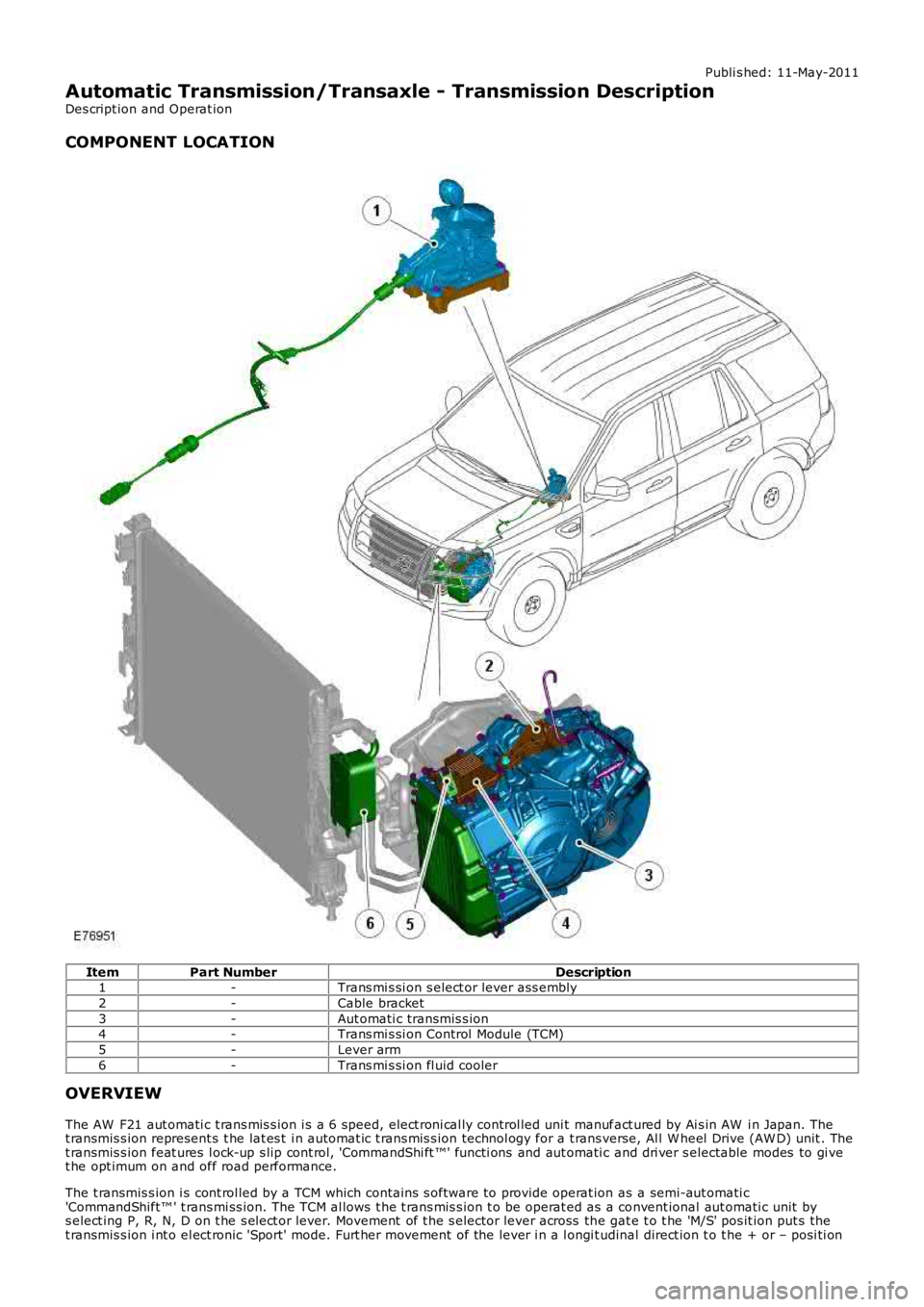
COMPONENT LOCATION
ItemPart NumberDescription1-Trans mi s si on s elect or lever ass embly
2-Cable bracket
3-Aut omati c transmis s ion4-Trans mi s si on Control Module (TCM)
5-Lever arm
6-Trans mi s si on fl uid cooler
OVERVIEW
The AW F21 aut omati c t rans mis s ion i s a 6 speed, elect roni cal ly control led uni t manufact ured by Ai s in AW i n Japan. Thet ransmis s ion represent s t he lat es t i n automat ic t rans mis s ion technol ogy for a t rans verse, Al l W heel Drive (AW D) unit . Thet ransmis s ion feat ures l ock-up s lip cont rol, 'CommandShi ft ™' functi ons and aut omati c and dri ver s electable modes to gi vet he opt imum on and off road performance.
The t ransmis s ion i s cont rol led by a TCM which contains s oftware to provide operat ion as a semi-aut omati c'CommandShift™ ' t rans mi ss ion. The TCM al lows t he t rans mis s ion t o be operat ed as a convent ional aut omati c unit bys elect ing P, R, N, D on t he s el ect or lever. Movement of t he s elector lever across the gat e t o t he 'M/S' pos it ion put s thet ransmis s ion i nt o el ect ronic 'Sport' mode. Furt her movement of the lever i n a l ongi tudinal direct ion t o t he + or – posi ti on
Page 1292 of 3229
4-TCM
5-Selector l ever
6-Selector l ever PRND and M/S Li ght Emi tt ing Diode (LED) dis plays7-Hi gh s peed CAN bus to ot her vehi cl e s ys t ems
8-Inst rument clus t er
9-St eering angle sens or10-ABS modul e
11-ECM
INSTRUMENT CLUSTER
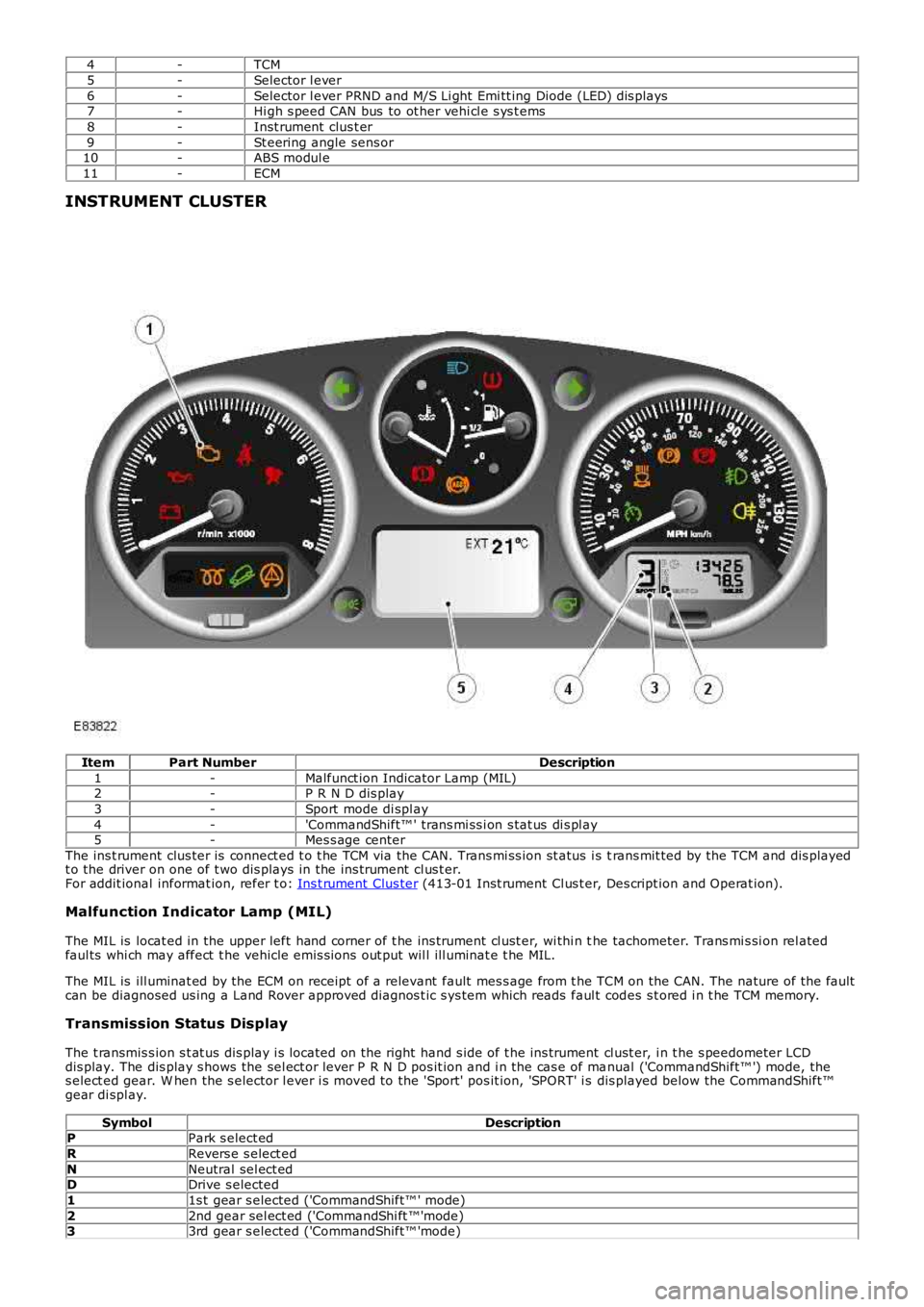
ItemPart NumberDescription
1-Malfunct ion Indicator Lamp (MIL)2-P R N D dis play
3-Sport mode di spl ay
4-'CommandShift™ ' trans mi ss i on s tat us di s pl ay5-Mes s age center
The ins t rument clus ter is connect ed t o t he TCM via the CAN. Trans mi ss ion st atus i s trans mit ted by the TCM and dis playedt o the driver on one of t wo dis plays in the ins trument cl us t er.For addit ional informat ion, refer t o: Ins t rument Clus ter (413-01 Inst rument Cl us t er, Des cript ion and Operat ion).
Malfunction Indicator Lamp (MIL)
The MIL is locat ed in the upper left hand corner of t he ins trument cl ust er, wi thi n the tachometer. Trans mi s si on rel atedfaul ts whi ch may affect t he vehicle emis si ons out put wil l ill uminat e t he MIL.
The MIL is ill uminat ed by the ECM on receipt of a relevant fault mes s age from t he TCM on the CAN. The nature of the faultcan be diagnosed us ing a Land Rover approved diagnos t ic s ys tem which reads faul t codes s t ored i n t he TCM memory.
Transmission Status Display
The t ransmis s ion s t at us dis play i s located on the right hand s ide of t he ins trument cl ust er, i n t he s peedometer LCDdis play. The dis play s hows the sel ect or lever P R N D pos it ion and i n the cas e of manual ('CommandShift™ ') mode, thes elect ed gear. W hen the s elector l ever i s moved to the 'Sport' pos it ion, 'SPORT' i s dis played below the CommandShift™gear di spl ay.
SymbolDescriptionPPark s elect ed
RRevers e s elect ed
NNeutral sel ect edDDrive s elected
11s t gear s elected ('CommandShift™ ' mode)
22nd gear sel ect ed ('CommandShi ft ™'mode)33rd gear s elected ('CommandShift™ 'mode)
Page 1293 of 3229
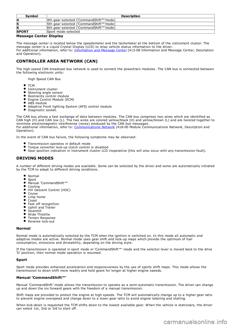
SymbolDescription
44th gear s elected ('CommandShift™ 'mode)
55th gear s elected ('CommandShift™ 'mode)66th gear s elected ('CommandShift™ 'mode)
SPORTSport mode s elected
Message Center Display
The mes s age center i s located bel ow t he speedometer and t he tachometer at t he bot t om of t he ins trument cl ust er. Themes s age center i s a Liqui d Crys tal Di spl ay (LCD) t o rel ay vehi cl e s tat us informat ion t o t he dri ver.For addit ional informat ion, refer t o: Informat ion and Mes s age Cent er (413-08 Informat ion and Mes s age Cent er, Des cript ionand Operat ion).
CONTROLLER AREA NETWORK (CAN)
The high s peed CAN broadcast bus net work i s us ed to connect t he powert rai n modules . The CAN bus is connect ed betweent he foll owing el ect ronic uni ts :
High Speed CAN Bus
TCMIns t rument clus terSteering angle s ens orRest rai nts control modul eEngi ne Control Module (ECM)ABS moduleAdapt ive Front l ight ing Syst em (AFS) cont rol moduleDiagnost ic socket .
The CAN bus all ows a fast exchange of dat a between modules . The CAN bus compri ses two wires which are identi fied asCAN hi gh (H) and CAN low (L). The t wo wires are colored yel low/bl ack (H) and yell ow/brown (L) and are twi s ted t oget her tomi ni mi se el ect romagneti c int erference (nois e) produced by the CAN bus mes sages .For addit ional informat ion, refer t o: Communicati ons Net work (418-00 Modul e Communicati ons Net work, Des cript ion andOperat ion).
In the event of CAN bus fai lure, t he fol lowi ng s ympt oms may be obs erved:
Trans mis s ion operat es in default modeTorque converter lock-up clut ch cont rol is dis abl edGear pos it ion indicati on in ins trument cl us t er LCD inoperati ve (t his will al so occur wit h any t rans mis s ion faul t).
DRIVING MODES
A number of different dri ving modes are avai lable. Some can be s elected by the driver and some are aut omati cal ly i nit iatedby t he TCM t o adapt t o di fferent drivi ng condit ions .
NormalSportManual 'CommandShift ™'CoolingHil l Descent Cont rol (HDC)Crui seLimp homeCoastFast off recogni ti onUphill and TrailerDownhillW i de Throt tl eTerrai n Res pons eRevers e lock-out
Normal
Normal mode is automat icall y s elect ed by t he TCM when t he i gni ti on is swi tched on. In this mode all automat ic andadapt ive modes are acti ve. Normal mode uses gear s hi ft and l ock-up maps which provi de the opt imum of fuelcons umpt ion, emis s ions and dri veabil it y, depending on t he dri ving s tyl e.
If the t rans mis s ion is operat ed in sport mode or 'CommandShi ft ™' mode and t he s elector lever is moved back t o t he drive'D' pos it ion, then normal mode operat ion is resumed.
Sport
Sport mode provi des enhanced accelerat ion and respons ivenes s by t he us e of s ports shi ft maps . This mode al lows t het ransmis s ion t o down s hift more readil y and hol d gears for longer at hi gher engine speeds .
Manual 'CommandShift™'
Manual 'CommandShift ' mode al lows t he t rans mis s ion t o operat e as a semi -aut omati c trans mi s si on. The driver can changeup and down t he s ix forward gears wi th the freedom of a manual t rans mis s ion.
Shift maps are provi ded to protect t he engi ne at high s peeds . The TCM wi ll automat icall y change up t o a higher gear rat iot o prevent engine overspeed and change down to a lower gear rati o t o avoi d engine l aboring and s t al li ng.
W hen ki ck-down is reques ted the TCM shi ft s down t o t he lowes t avai lable gear. W hen the vehicl e is st ati onary, t he drivercan s el ect 1s t , 2nd or 3rd t o s tart off.
Page 1370 of 3229
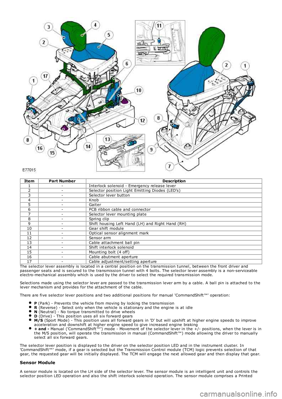
ItemPart NumberDescription
1-Interlock sol enoi d - Emergency rel eas e l ever2-Selector pos it ion Light Emi tt ing Di odes (LED's )
3-Selector l ever butt on
4-Knob5-Gait er
6-PCB ribbon cabl e and connector
7-Selector l ever mounti ng plat e8-Spri ng clip
9-Shift hous i ng Left Hand (LH) and Ri ght Hand (RH)
10-Gear s hi ft modul e11-Opt ical sens or al ignment mark
12-Sensor arm
13-Cable at t achment ball pin14-Shift int erlock s olenoid
15-Mounti ng bolt (4 off)
16-Cable abut ment aperture17-Cable adjust ment/s ett ing apert ure
The s elect or lever ass embly is l ocat ed in a cent ral posi ti on on t he t ransmis s ion t unnel , bet ween the front driver andpass enger s eats and is s ecured t o t he transmis si on t unnel wit h 4 bol ts . The s elector lever ass embly is a non-s erviceabl eelectro-mechani cal as s embly whi ch is us ed by t he dri ver t o s elect the requi red t ransmi ss i on mode.
Selecti ons made usi ng the sel ect or lever are pass ed t o t he t rans mis s ion l ever arm by a cable. A bal l pi n i s att ached t o t helever mechanis m and provides for the at tachment of t he cable.
There are fi ve s elect or lever pos i ti ons and t wo addit ional pos i ti ons for manual 'CommandShi ft ™' operati on:
P (Park) - Prevents t he vehicle from moving by locki ng the trans mi ss i onR (Revers e) - Sel ect only when the vehicle is s t ati onary and the engi ne is at i dleN (Neutral) - No torque trans mi tt ed t o dri ve wheel sD (Drive) - Thi s pos it ion us es all s ix forward gearsM/S (Sport Mode) - This pos it ion us es all forward gears in 'D' but wil l ups hift at hi gher engine s peeds to improveaccelerati on and downs hift at higher engine speed t o give i ncreased engine braki ng+ and - Manual ('CommandShi ft ™') mode - Movement of t he s elector lever in the +/- posi ti ons, when t he l ever is int he M/S pos i ti on, wi ll operate the trans mi ss i on in manual (CommandShift ™) mode all owing t he dri ver t o manuall ys elect al l si x forward gears.
The s elect or lever pos i ti on is di spl ayed t o t he dri ver on the s elector pos it ion LED and i n t he ins trument cl ust er. In'CommandShift™ ' mode, i f a gear i s s elected but t he Trans mis s ion Control modul e (TCM) logic prevent s s el ect ion of t hatgear, t he request ed gear will be init iall y dis played. The TCM wil l engage t he next al lowed gear and then di spl ay that gear.
Sensor Module
A s ens or modul e is locat ed on t he LH s ide of t he s elector lever. The s ens or modul e is an int el li gent unit and controls t hes elect or posi ti on LED operati on and als o t he s hift interlock s olenoi d operat ion. The sens or modul e compri ses a Pri nt ed
Page 1371 of 3229
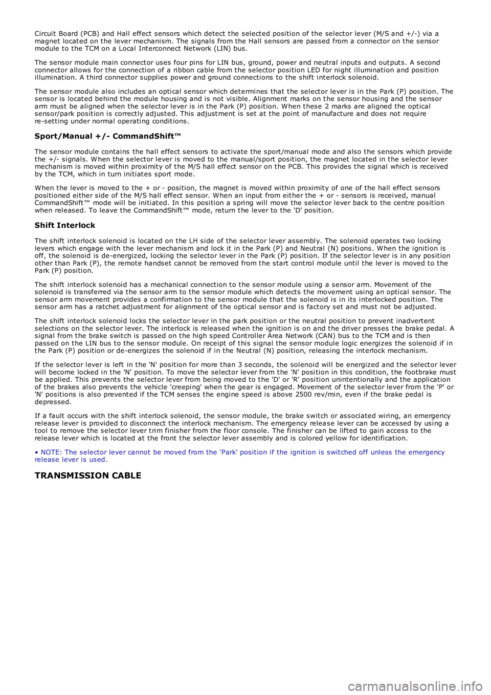
Circui t Board (PCB) and Hal l effect s ensors which detect t he s el ect ed posi ti on of the sel ect or lever (M/S and +/-) via amagnet locat ed on t he lever mechani sm. The si gnal s from t he Hall s ens ors are pas s ed from a connector on t he s ens ormodule t o t he TCM on a Local Int erconnect Network (LIN) bus .
The s ens or module main connect or us es four pins for LIN bus , ground, power and neutral inputs and out put s . A s econdconnector all ows for t he connecti on of a ri bbon cable from t he s elector posi ti on LED for ni ght i ll uminati on and posi ti onil lumi nat ion. A t hird connector s uppl ies power and ground connecti ons to the s hift int erl ock s olenoid.
The s ens or module al so includes an opti cal s ensor which det ermi nes that t he sel ect or lever i s i n the Park (P) pos it ion. Thes ens or is locat ed behind t he module hous ing and i s not vi s ible. Ali gnment marks on the s ens or housi ng and the sens orarm mus t be ali gned when the s elect or l ever i s in the Park (P) pos it ion. W hen t hes e 2 marks are ali gned the opt icals ens or/park pos it ion i s correct ly adjus t ed. This adjust ment is set at t he point of manufacture and does not requi rere-s et t ing under normal operati ng condit ions .
Sport/Manual +/- CommandShift™
The s ens or module contai ns the hal l effect s ens ors to act ivate the s port /manual mode and als o t he s ensors which provi det he +/- s i gnal s. W hen the s elect or l ever i s moved to the manual /s port pos it ion, the magnet located in t he s elector levermechani sm i s moved wit hin proxi mit y of t he M/S hall effect s ensor on t he PCB. This provi des t he s ignal which i s receivedby t he TCM, which in turn ini ti at es s port mode.
W hen t he l ever is moved to the + or - pos i ti on, t he magnet is moved wi thi n proximit y of one of the hall effect sens orsposi ti oned ei ther s ide of t he M/S hall effect s ens or. W hen an input from eit her the + or - s ens ors is recei ved, manualCommandShi ft ™ mode wil l be ini ti at ed. In this pos i ti on a s pri ng wil l move the s elector l ever back to the centre pos it ionwhen rel eas ed. To leave t he CommandShi ft ™ mode, return t he lever to the 'D' pos it ion.
Shift Interlock
The s hift interlock s ol enoi d i s located on t he LH s i de of the s elector l ever as sembly. The sol enoid operates t wo l ockinglevers whi ch engage wi th the lever mechanis m and lock it i n t he Park (P) and Neut ral (N) pos i ti ons . W hen t he i gni ti on isoff, the sol enoid is de-energized, l ocking the s elector l ever i n the Park (P) pos it ion. If the s elector l ever i s in any pos it ionother t han Park (P), t he remot e hands et cannot be removed from t he s tart cont rol module unt il t he lever is moved t o t hePark (P) posi ti on.
The s hift interlock s ol enoi d has a mechanical connect ion t o t he s ens or module us ing a s ens or arm. Movement of thes olenoi d i s transferred via t he s ensor arm t o t he s ens or module whi ch det ect s t he movement usi ng an opti cal s ensor. Thes ens or arm movement provides a confi rmat ion t o t he s ens or module t hat the sol enoid is i n i ts i nterlocked pos it ion. Thes ens or arm has a ratchet adjust ment for al ignment of t he opti cal s ensor and i s fact ory s et and mus t not be adjust ed.
The s hift interlock s ol enoi d l ocks t he s el ect or lever in t he park pos it ion or t he neutral pos it ion t o prevent inadvert ents elect ions on the s elector l ever. The interlock is releas ed when t he ignit ion i s on and t he dri ver pres s es t he brake pedal . As ignal from t he brake s wit ch is pas s ed on t he high s peed Cont rol ler Area Net work (CAN) bus t o t he TCM and i s thenpass ed on t he LIN bus t o the sens or modul e. On receipt of t hi s s ignal the s ens or modul e logic energi zes the s olenoid if i nt he Park (P) pos it ion or de-energizes the sol enoid if i n t he Neut ral (N) posi ti on, releas ing t he int erlock mechani s m.
If the s elector l ever is left in t he 'N' pos it ion for more t han 3 s econds , the sol enoi d wil l be energized and t he s el ect or leverwil l become locked i n t he 'N' posi ti on. To move the sel ect or lever from t he 'N' positi on in this condit ion, t he footbrake mus tbe applied. This prevent s the sel ect or lever from being moved t o t he 'D' or 'R' positi on unintent ionally and the appli cat ionof the brakes al s o prevent s t he vehi cle 'creepi ng' when t he gear is engaged. Movement of t he s elector lever from t he 'P' or'N' pos it ions is al s o prevent ed i f the TCM sens es t he engi ne s peed i s above 2500 rev/mi n, even i f the brake pedal isdepres sed.
If a fault occurs wi th the s hift int erl ock s olenoid, t he s ens or module, the brake s wit ch or as s oci ated wi ri ng, an emergencyrel eas e l ever i s provided t o dis connect t he int erlock mechani sm. The emergency releas e lever can be acces sed by us i ng at ool t o remove the s elector l ever t ri m finis her from t he floor cons ole. The fi nis her can be lifted to gai n acces s t o therel eas e l ever whi ch is l ocat ed at the front t he s elect or lever ass embly and is colored yel low for identi fi cat ion.
• NOTE: The s elector lever cannot be moved from the 'Park' pos it ion i f the ignit ion i s s wit ched off unl ess the emergencyrel eas e l ever i s us ed.
TRANSMISSION CABLE
Page 1823 of 3229
Publ is hed: 20-Oct -2011
Battery and Charging System - General Information - Quiescent Drain
Des cript ion and Operat ion
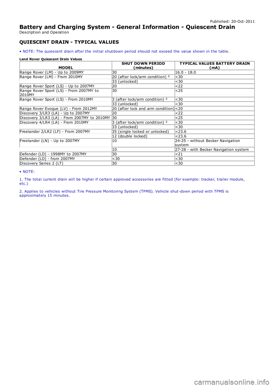
QUIESCENT DRAIN - TYPICAL VALUES
• NOTE: The quies cent drai n aft er the init ial s hut down peri od s hould not exceed the val ue shown in t he t abl e.
Land Rover Quiescent Drain Values
MODELSHUT DO WN PER IOD(minutes)T YPICAL VALUES BAT T ERY DRAIN(mA)
Range Rover (LM) - Up t o 2009MY3016.0 - 18.0Range Rover (LM) - From 2010MY20 (aft er l ock/arm condit ion) ²<30
33 (unl ocked)<30
Range Rover Sport (LS) - Up t o 2007MY20<22Range Rover Sport (LS) - From 2007MY t o2010MY30<25
Range Rover Sport (LS) - From 2010MY3 (aft er lock/arm condit ion) ²<30
33 (unl ocked)<30
Range Rover Evoque (LV) - From 2012MY20 (aft er l ock and arm condit ion)<20Di scovery 3/LR3 (LA) - Up t o 2007MY20<22
Di scovery 3/LR3 (LA) - From 2007MY to 2010MY30<25
Di scovery 4/LR4 (LA) - From 2010MY3 (aft er lock/arm condit ion) ²<3033 (unl ocked)<30
Freelander 2/LR2 (LF) - From 2007MY35 (si ngl e l ocked or unlocked)<23.6
12 (double locked)<23.6Freelander (LN) - Up to 2007MY1024-25 - wi thout Becker Navi gati onsys t em
1027-28 - wi th Becker Navi gat ion s ys temDefender (LD) - 1998MY t o 2007MY30<21
Defender (LD) - from 2007MY<30<30
Di scovery Seri es 2 (LT)30<30
• NOTE:
1. The tot al current drain wil l be higher i f certai n approved acces sories are fi tt ed (for exampl e: tracker, t rai ler module,etc.)
2. Appl ies t o vehicles wi thout Tire Pres s ure Monit ori ng Syst em (TPMS). Vehicle shut -down peri od wi th TPMS isapproximat el y 15 minutes .
Page 1830 of 3229
• NOTE: The fus i bl e l inks are mount ed on t he inboard s i de of the BJB behind a series of removable covers .
The CJB is mount ed behind t he glovebox and recei ves it s main power s uppl y from the BJB. In addi ti on to cont aining bl adefus es , the CJB i s t he main controll er for a number of vehicle s ys t ems. Thes e functi ons are out li ned in t he rel evant s ect ionsof thi s manual .
The AJB is locat ed beneat h t he luggage compartment carpet , adjacent t he spare wheel wel l. The AJB i s a modular des ign,and compris es up t o 3 individual elements depending on vehicle specificati on. The AJB cont ains bl ade and J-cas e fuses ,and rel ays to di st ribute el ect ri cal power to sys t ems used at the rear of t he vehi cle. The AJB receives it s mai n power s upplyfrom the BJB.
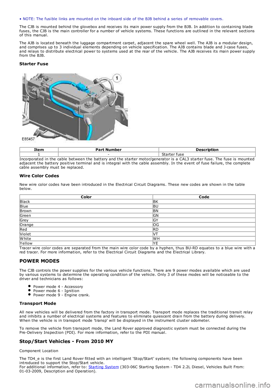
Starter Fuse
ItemPart NumberDescription
1-Starter fus e
Incorporat ed i n the cable bet ween t he bat t ery and t he s tarter mot or/generat or is a CAL3 st art er fus e. The fus e is mount edadjacent t he batt ery pos it ive t erminal and is i ntegral wi th t he cable as s embly. In the event of fus e fai lure, t he completecabl e as sembl y mus t be repl aced.
Wire Color Codes
New wi re col or codes have been i ntroduced i n the El ect ri cal Ci rcuit Di agrams . Thes e new codes are s hown i n t he tablebelow.
ColorCode
BlackBK
BlueBUBrownBN
GreenGN
GreyGYOrangeOG
RedRD
Viol etVTW hi teW H
Y ell owY E
Tracer wire col or codes are s eparat ed from the main wi re col or code by a hyphen, t hus BU-RD equat es to a blue wire wit h ared tracer. For more informat ion, refer to t he Elect rical Circui t Diagrams and the El ect ri cal Library.
POWER MODES
The CJB cont rol s the power s uppl ies for the vari ous vehi cl e functi ons. There are 9 power modes availabl e which are usedby vari ous s ys tems to det ermi ne t he operati ng condit ion of t he vehi cle. Only 3 of thes e modes wil l be noti ceable t o t hedri ver and t echnici ans as foll ows:
Power mode 4 - Acces s oryPower mode 6 - Igni ti onPower mode 9 - Engine crank.
Transport Mode
All new vehicles will be del ivered from the factory in t rans port mode. Trans port mode repl aces t he t radit ional trans i t relayand inhibi ts a number of el ect ri cal s ys t ems and feat ures t o eli mi nat e quies cent drain from the bat tery during del ivery.W hen t he vehicle i s in transport mode 't rans p' wi ll be di spl ayed i n t he ins trument cl ust er odomet er.
To remove the vehicle from t rans port mode, the Land Rover approved di agnos ti c s ys t em mus t be connect ed during t hePre-Delivery Ins pect ion (PDI). For more i nformati on, refer t o the PDI manual .
Stop/Start Vehicles - From 2010 MY
Component Locat ion
The TD4_e is t he first Land Rover fit t ed wit h an i ntell igent ‘St op/Start’ s yst em; t he fol lowing component s have beenint roduced to support t he Stop/St art vehicle.For addit ional informat ion, refer t o: Starti ng Sys t em (303-06C Starti ng Syst em - TD4 2.2L Di es el, Vehicles Bui lt From:01-03-2009, Descripti on and Operat ion).
Page 1953 of 3229
5-Rear door module
6-Rear i nterior lamp
7-Luggage compart ment lamp8-Rear door lat ch swit ch
9-Rear door module
10-Dri ver door lat ch swi tch11-Dri ver door lamp
12-Dri ver door module
13-Ext eri or mirror lamp14-Vani ty mirror l amp
15-Dri ver foot well l amp
16-Pas s enger foot well l amp17-Cent ral Junct ion Box (CJB)
18-Pas s enger door lamp
19-Glovebox lamp20-Pas s enger door module
21-Ext eri or mirror lamp
22-Pas s enger door lat ch swi tch
OVERVIEW
Operat ion of t he int erior l ighti ng s ys t em, wit h t he excepti on of the door and mi rror lamps , is controlled by the CJB. Doorand mi rror l amp operat ion i s cont rol led by t he rel evant door modul e.
In order to cont rol t he int erior l ighti ng s ys t em, the CJB recei ves i nput s from the 4 door l atch s wit ches and the l iftgat erel eas e motor. The s ys tem als o i nt eracts wit h t he cent ral locking s ys tem, i lluminating the interior lamps and the mirrorlamps on receipt of an unlock request . This reques t is trans mi tt ed t o t he CJB from the Radio Frequency (RF) receiver.
The front and rear roof mounted interior lamps contai n a 3 pos i ti on rocker s wi tch. Aut omati c (Courtes y) operati on of thelamps can be overridden by movi ng the s wi tch t o t he 'al ways on' or 'always off' positi on.
If 'Court es y' li ght ing i s acti ve and a hinged panel i s left open, t he CJB wil l ext inguis h all i nterior lamps after a period of 15mi nut es. If a manual request for int erior l ighti ng has been made, t he CJB wi ll exti nguis h the l amps aft er a peri od of 30mi nut es.
Pres s ing t he li ght symbol on t he remot e hands et wi ll act ivat e t he 'Approach Lamp' feat ure. W hen act ivated, t he CJBil lumi nat es t he mirror l amps and a number of ext eri or l amps.For addit ional informat ion, refer t o: Ext eri or Li ght ing (417-01 Ext erior Light ing, Descri pti on and Operat ion).
On vehicles from 2009MY , t he front int erior l amp incorporat es 2 map reading l amps. The front i nt eri or lamp i s fit ted wi th 2addi ti onal s wi tches which cont rol each lamp and operate i ndependant ly of t he i nt eri or light ing funct ionalit y.
Transport Mode
All new vehicles will be del ivered from the factory in t rans port mode. Trans port mode i nhi bit s a number of el ect ri cals ys t ems and feat ures , including t he i nt eri or lamps , to el imi nate qui es cent drain from t he bat t ery duri ng delivery. W hen thevehi cl e i s in trans port mode 't ransp' wi ll be dis played i n the ins trument cl us t er odomet er.
To remove the vehicle from t rans port mode, the Land Rover approved di agnos ti c s ys t em mus t be connect ed during t hePre-Delivery Ins pect ion (PDI). For more i nformati on, refer t o the PDI manual .
CONTROL DIAGRAM
• NOTE: A = Hardwi red; N = Medium s peed Cont roll er Area Net work (CAN) bus