four wheel drive LAND ROVER FRELANDER 2 2006 Repair Manual
[x] Cancel search | Manufacturer: LAND ROVER, Model Year: 2006, Model line: FRELANDER 2, Model: LAND ROVER FRELANDER 2 2006Pages: 3229, PDF Size: 78.5 MB
Page 165 of 3229
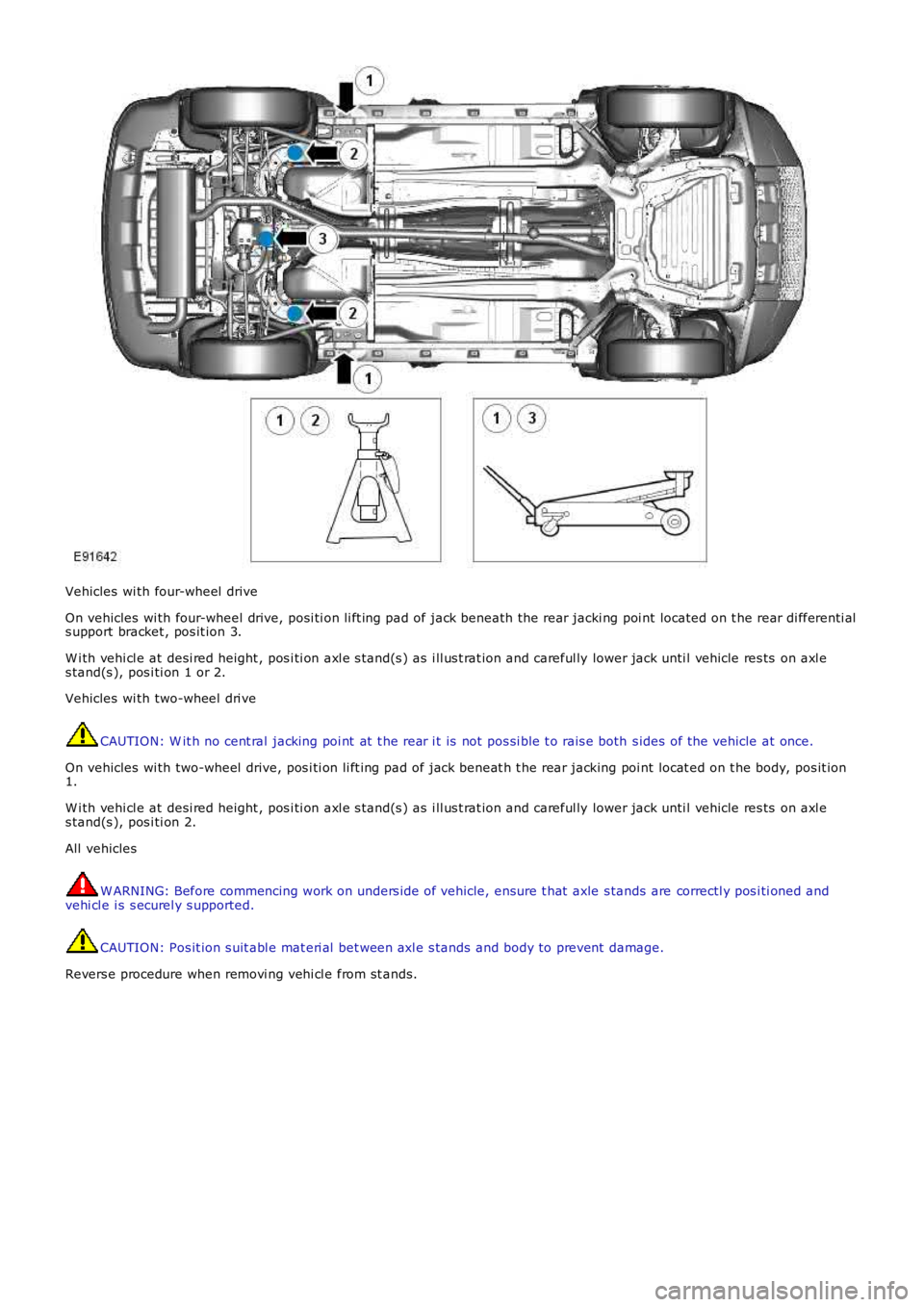
Vehicles wi th four-wheel drive
On vehicles wi th four-wheel drive, posi ti on li ft ing pad of jack beneath the rear jacki ng poi nt located on t he rear di fferenti als upport bracket , pos it ion 3.
W i th vehi cl e at desi red height , pos i ti on axl e s tand(s ) as i ll us t rat ion and careful ly lower jack unti l vehicle res ts on axl es tand(s ), pos i ti on 1 or 2.
Vehicles wi th two-wheel dri ve
CAUTION: W it h no cent ral jacking poi nt at t he rear i t is not pos si ble t o rais e both s ides of the vehicle at once.
On vehicles wi th two-wheel drive, pos i ti on li ft ing pad of jack beneat h t he rear jacking poi nt locat ed on t he body, pos it ion1.
W i th vehi cl e at desi red height , pos i ti on axl e s tand(s ) as i ll us t rat ion and careful ly lower jack unti l vehicle res ts on axl es tand(s ), pos i ti on 2.
All vehicles
W ARNING: Before commencing work on unders ide of vehicle, ensure t hat axle s tands are correctl y pos i ti oned andvehi cl e i s s ecurel y s upported.
CAUTION: Pos it ion s uit abl e mat eri al bet ween axl e s tands and body to prevent damage.
Revers e procedure when removi ng vehi cl e from st ands.
Page 166 of 3229
Publi s hed: 11-May-2011
Jacking and Lifting - Lifting
Des cript ion and Operat ion
Two-Post Lift
W ARNING: Make sure t hat t he vehicle i s s table before commencing work.
CAUTION: If the drive s haft (s ) are to be removed, rel eas e t he parking brake and s el ect NEUTRAL 'N' i n t het ransmis s ion i n order t hat t he s haft (s ) can be rot ated when the vehicle is rais ed to the des ired height.
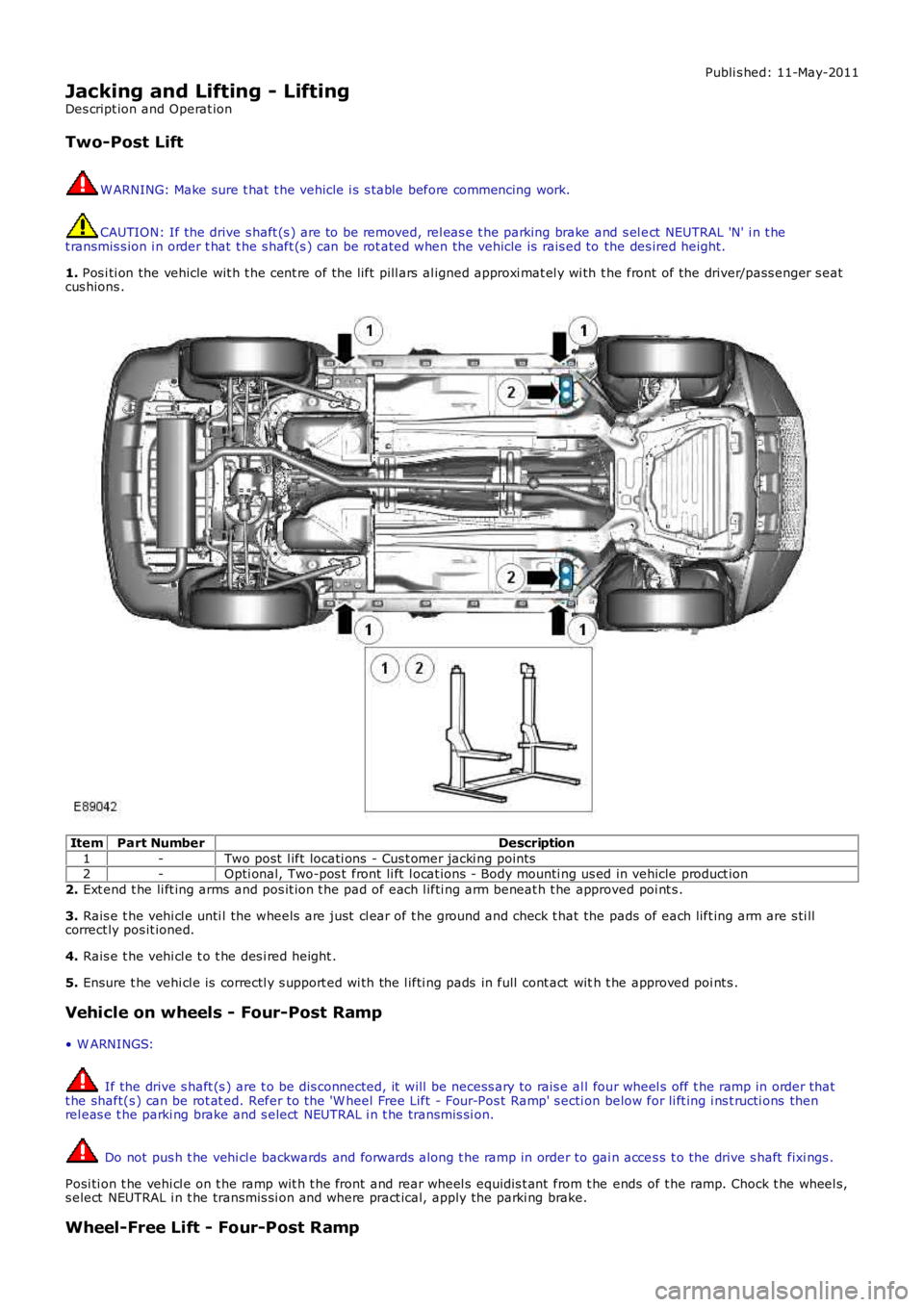
1. Pos i ti on the vehicle wit h t he cent re of the l ift pill ars al igned approxi mat el y wi th t he front of the driver/pass enger s eatcus hions .
ItemPart NumberDescription
1-Two post l ift locati ons - Cus t omer jacki ng points2-Opti onal, Two-pos t front li ft l ocat ions - Body mounti ng us ed in vehicle product ion
2. Ext end t he li ft ing arms and pos it ion t he pad of each l ifti ng arm beneat h t he approved poi nt s .
3. Rais e t he vehi cl e unti l the wheels are just cl ear of t he ground and check t hat the pads of each lift ing arm are s ti llcorrect ly pos it ioned.
4. Rais e t he vehi cl e t o t he des i red height .
5. Ensure t he vehi cl e is correctl y s upport ed wi th the l ifti ng pads in full cont act with t he approved poi nt s .
Vehicle on wheels - Four-Post Ramp
• W ARNINGS:
If the drive s haft (s ) are t o be dis connected, it will be necess ary to rais e al l four wheel s off t he ramp in order thatt he shaft(s ) can be rot at ed. Refer to the 'W heel Free Lift - Four-Pos t Ramp' s ecti on below for li ft ing i ns t ructi ons thenrel eas e t he parki ng brake and s elect NEUTRAL i n t he transmis si on.
Do not pus h t he vehi cl e backwards and forwards along t he ramp in order to gai n acces s t o the drive s haft fixi ngs .
Posi ti on t he vehi cl e on t he ramp wit h t he front and rear wheel s equidis t ant from t he ends of t he ramp. Chock t he wheel s,s elect NEUTRAL i n t he transmis si on and where pract ical, apply the parki ng brake.
Wheel-Free Lift - Four-Post Ramp
Page 195 of 3229
Publi s hed: 11-May-2011
Suspension System - General Information - Suspension System
Diagnosi s and Tes ti ng
Principles of Operation
For a detail ed descripti on of the sus pens i on sys t em, refer t o t he rel evant Des cript ion and Operat ion s ecti on in theworks hop manual . REFER to:
Front Sus pensi on (204-01 Front Sus pensi on, Des cri pti on and Operati on),Rear Sus pens ion (204-02 Rear Suspens ion, Descri pti on and Operat ion),Ride and Handli ng Opti mizati on (204-06 Ride and Handli ng Opti mizat ion, Descri pti on and Operat ion).
Inspection and Verification
1. Verify t he cus t omer concern.1.
2. Vis ually ins pect for obvious s igns of damage.2.
Visual InspectionMechanical
Damaged t iresW heel bearing(s)Loose or damaged front or rear s uspens ion component sLoose, damaged or mis s ing s us pens ion fas tener(s )Incorrect spring(s ) i ns t alledDamaged or s aggi ng spring(s )Damaged or leaking s hock abs orber(s )Damaged or leaking s t rut (s )W orn or damaged s us pensi on bushi ng(s )Loose, worn or damaged s t eering sys tem componentsDamaged axle component s
3. If an obvious cause for an obs erved or report ed concern is found, correct t he caus e (if pos s ible) beforeproceeding t o t he next s t ep.3.
4. If t he caus e is not vis ually evi dent , verify t he sympt om and refer t o t he Sympt om Chart.4.
Symptom Chart
SymptomPossible CauseAction
CrabbingIncorrect rear thrus t angleFront or rear s uspens ioncomponent sDrive axle damaged
CHECK t he rear toe adjust ment.REFER to: Speci fi cat ions (204-00 Suspens ion Syst em - GeneralInformat ion, Specificati ons) /Four-W heel Al ignment (204-00 Sus pens i on Sys t em - GeneralInformat ion, General Procedures ).INSPECT t he front and rear s us pensi on s yst ems . REPAIR orINSTALL new s us pens ion component s as neces s ary. INSTALL a newrear dri ve axl e/di fferenti al as necess ary
Drift/Pul lUnequal t ire pres s ureIncorrect wheel ali gnmentTiresUnevenl y loaded oroverloaded vehi cleDamaged s teeri ngcomponent sBrake drag
CHECK and ADJUST the t ire pres s ures . INSPECT t he ti re forexces si ve wear.REFER to: Speci fi cat ions (204-04 W heels and Ti res , Specificati ons ).CHECK and ADJUST the wheel ali gnment .REFER to: Four-W heel Al ignment (204-00 Sus pensi on Syst em -General Informat ion, General Procedures ).CHECK and ADJUST the t ire pres s ures . INSPECT t he ti re forexces si ve wear.REFER to: Speci fi cat ions (204-04 W heels and Ti res , Specificati ons ).NOTIFY the cus tomer of incorrect vehicle l oadi ng. CHECK thes teeri ng s ys t em.REFER to: St eering Sys tem (211-00 St eeri ng Sys t em - GeneralInformat ion, Diagnosi s and Test ing).CHECK t he brakes .REFER to: Brake Sys tem (206-00 Brake Syst em - GeneralInformat ion, Diagnosi s and Test ing).Front Bott omi ng orRidi ng LowCoil s pri ngsCHECK t he ri de hei ght. INSTALL new springs as neces s ary.REFER to: Spri ng (204-01 Front Sus pensi on, Removal andIns t al lat ion) /Rear Shock Absorber (204-02 Rear Sus pensi on, Removal andIns t al lat ion).
Incorrect Ti re W earIncorrect ti re press ure(rapid center rib or i nnerand outer edge wear)Exces s ive front or rear toe(rapid inner or out er edgewear)Exces s ive negat ive orposi ti ve camber (rapi dinner or out er edge wear)Tires out of bal ance (ti rescupped or dis hed)
CHECK and ADJUST the t ire pres s ure. INSPECT t he t ire forexces si ve wear.REFER to: Speci fi cat ions (204-04 W heels and Ti res , Specificati ons ).CHECK and ADJUST the wheel ali gnment .REFER to: Four-W heel Al ignment (204-00 Sus pensi on Syst em -General Informat ion, General Procedures ).BALANCE the wheels /ti res
Page 277 of 3229
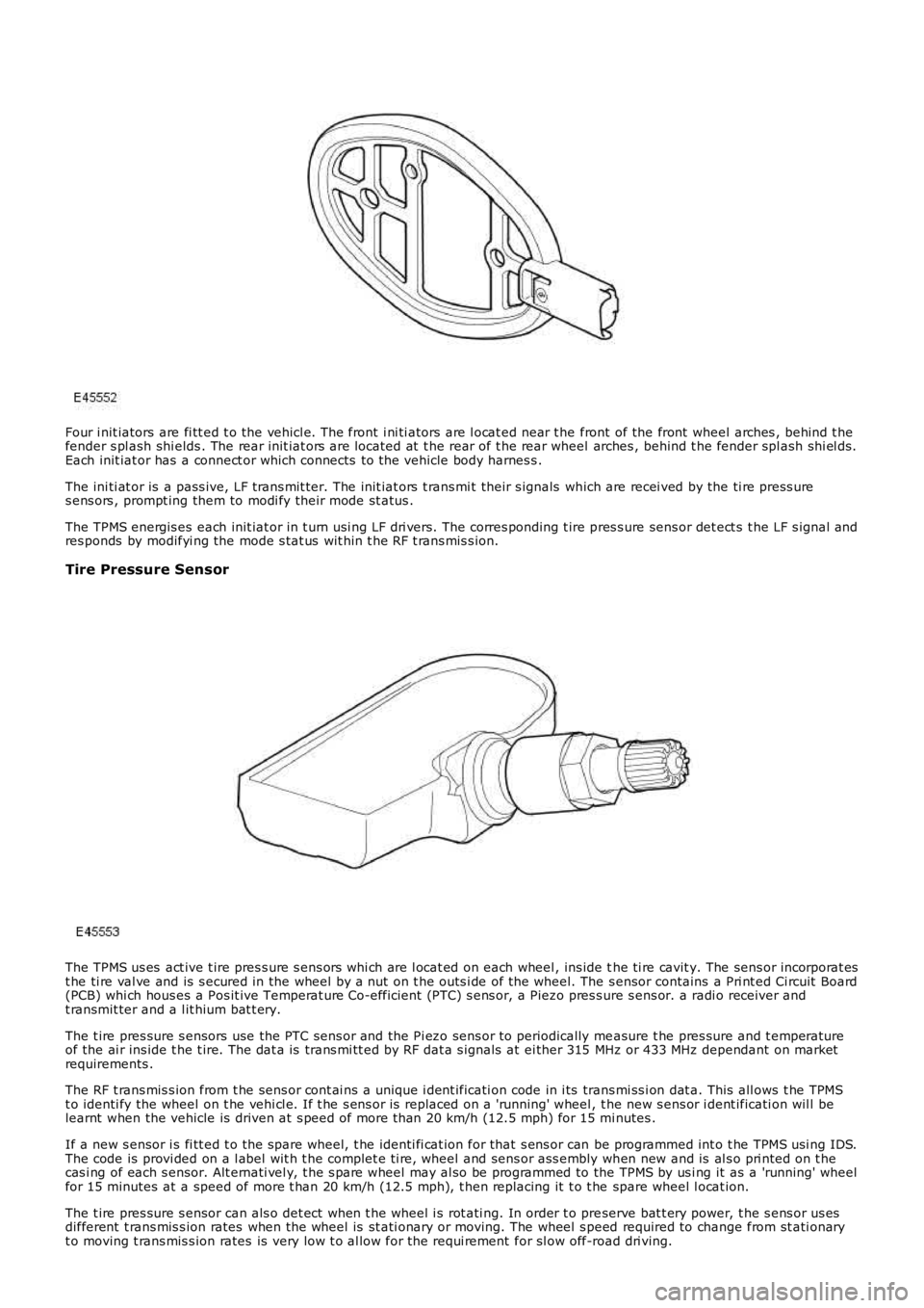
Four i nit iators are fi tt ed t o the vehicl e. The front i ni ti ators are l ocat ed near t he front of the front wheel arches , behind t hefender s pl ash shi elds . The rear init iat ors are located at t he rear of t he rear wheel arches , behind t he fender spl ash shi el ds.Each init iat or has a connect or which connects to the vehicle body harnes s .
The ini ti at or is a pass ive, LF t rans mit ter. The init iat ors t rans mi t their s ignals which are recei ved by the ti re press ures ens ors , prompt ing them to modi fy their mode st atus .
The TPMS energis es each init iat or in t urn usi ng LF dri vers. The corres ponding t ire pres s ure sens or det ect s t he LF s ignal andres ponds by modifyi ng the mode s tat us wit hin t he RF t rans mis s ion.
Tire Pressure Sensor
The TPMS us es act ive t ire pres s ure s ens ors whi ch are l ocat ed on each wheel , ins ide the ti re cavit y. The sens or incorporat est he ti re val ve and is s ecured in the wheel by a nut on t he outs i de of the wheel. The s ensor contains a Pri nt ed Ci rcuit Board(PCB) whi ch hous es a Pos it ive Temperat ure Co-efficient (PTC) s ens or, a Piezo pres s ure s ens or. a radi o receiver andt ransmit ter and a l it hium bat t ery.
The t ire pres sure s ensors use the PTC sens or and the Pi ezo sens or to periodically measure t he pres sure and t emperatureof the ai r ins ide t he t ire. The dat a is trans mi tt ed by RF dat a s ignals at ei ther 315 MHz or 433 MHz dependant on marketrequirements .
The RF t rans mis s ion from t he sens or cont ai ns a unique i dent ificati on code in i ts trans mi ss i on dat a. This all ows t he TPMSt o identi fy the wheel on t he vehi cl e. If t he s ens or is replaced on a 'running' wheel, t he new s ens or i dent ificati on wil l belearnt when the vehicle is driven at s peed of more t han 20 km/h (12.5 mph) for 15 minutes .
If a new s ensor i s fi tt ed t o t he spare wheel, t he identi fi cat ion for that s ens or can be programmed int o t he TPMS usi ng IDS.The code is provi ded on a l abel wit h t he complet e ti re, wheel and sens or ass embly when new and is al s o pri nted on t hecas i ng of each s ensor. Alt ernati vel y, t he s pare wheel may al so be programmed to the TPMS by us i ng it as a 'running' wheelfor 15 minutes at a speed of more t han 20 km/h (12.5 mph), t hen replacing it t o t he spare wheel l ocat ion.
The t ire pres sure s ensor can als o det ect when t he wheel i s rot ati ng. In order t o preserve bat t ery power, t he s ens or us esdifferent t rans mis s ion rates when the wheel is st ati onary or moving. The wheel s peed required to change from st ati onaryt o moving t rans mis s ion rates is very low t o al low for the requi rement for sl ow off-road dri ving.
Page 302 of 3229
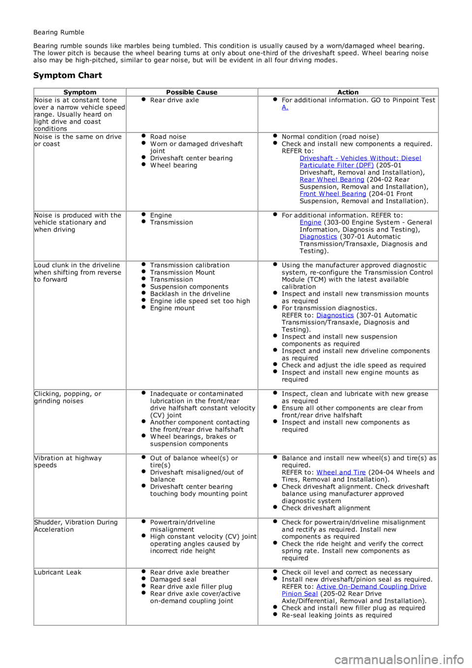
Bearing Rumbl e
Bearing rumble s ounds l ike marbl es being t umbled. Thi s condi ti on is us uall y caus ed by a worn/damaged wheel bearing.The lower pit ch is because the wheel bearing turns at onl y about one-t hird of the drives haft s peed. W heel bearing nois eals o may be high-pi tched, s imil ar t o gear noi s e, but wi ll be evident in al l four drivi ng modes.
Symptom Chart
SymptomPossible CauseActionNois e i s at cons t ant t oneover a narrow vehi cl e s peedrange. Us ual ly heard onl ight drive and coas tcondi ti ons
Rear drive axl eFor addi ti onal i nformat ion. GO to Pi npoi nt Tes tA.
Nois e i s t he s ame on driveor coas tRoad nois eW orn or damaged dri ves haftjoi ntDriveshaft cent er beari ngW heel bearing
Normal condit ion (road noi se)Check and ins tal l new components a required.REFER t o:Driveshaft - Vehi cl es W i thout: Di eselPart iculat e Fil ter (DPF) (205-01Driveshaft, Removal and Ins tall ati on),Rear W heel Bearing (204-02 RearSus pens ion, Removal and Inst all at ion),Front W heel Bearing (204-01 FrontSus pens ion, Removal and Inst all at ion).
Nois e i s produced wit h t hevehicle s t ati onary andwhen driving
EngineTrans mi ss ionFor addi ti onal i nformat ion. REFER to:Engine (303-00 Engine Syst em - GeneralInformat ion, Di agnos is and Tes ti ng),Di agnos ti cs (307-01 Aut omati cTrans mi ss ion/Transaxle, Di agnos is andTes ti ng).
Loud clunk in the driveli newhen s hifti ng from revers et o forward
Trans mi ss ion cal ibrat ionTrans mi ss ion MountTrans mi ss ionSus pens ion component sBackl ash in t he dri vel ineEngine i dl e s peed s et t oo highEngine mount
Us i ng the manufact urer approved diagnos t ics ys tem, re-configure t he Transmis s ion ControlModule (TCM) wi th the l ates t avai lablecali brati onIns pect and ins t al l new t ransmis s ion mount sas requi redFor t ransmis s ion diagnos ti cs .REFER t o: Diagnos t ics (307-01 Automat icTrans mi s si on/Trans axl e, Diagnos is andTes ti ng).Ins pect and ins t al l new s uspens ioncomponent s as requi redIns pect and ins t al l new dri vel ine component sas requi redCheck and adjus t the i dle s peed as requi redIns pect and ins t al l new engi ne mounts asrequi red
Cli cki ng, popping, orgri nding nois esInadequate or contami nat edl ubricati on in the front /reardri ve halfshaft cons tant veloci ty(CV) jointAnother component cont act ingt he front/rear dri ve hal fs haftW heel bearings , brakes ors uspens ion component s
Ins pect, cl ean and lubri cat e wit h new greaseas requi redEns ure al l ot her components are clear fromfront /rear drive halfs haftIns pect and ins t al l new components asrequi red
Vibrati on at highways peedsOut of balance wheel (s ) ort ire(s )Driveshaft mis ali gned/out ofbalanceDriveshaft cent er beari ngt ouching body mount ing point
Bal ance and i ns t all new wheel(s ) and ti re(s) asrequi red.REFER t o: W heel and Ti re (204-04 W heel s andTi res , Removal and Ins t allat ion).Check dri ves haft ali gnment . Check drives haftbalance us ing manufact urer approveddi agnos ti c s ys t emCheck dri ves haft ali gnment
Shudder, Vibrat ion DuringAccel erati onPowert rai n/dri vel inemi s al ignmentHi gh cons tant velocit y (CV) jointoperat ing angles caus ed byi ncorrect ride hei ght
Check for powert rai n/dri vel ine mis alignmentand rect ify as requi red. Ins t al l newcomponent s as requi redCheck the ri de hei ght and verify the corrects pri ng rat e. Ins t al l new components asrequi red
Lubricant LeakRear drive axl e breatherDamaged s ealRear drive axl e fi ll er pl ugRear drive axl e cover/acti veon-demand coupl ing joint
Check oil level and correct as neces s aryIns tall new drives haft/pinion seal as required.REFER t o: Act ive On-Demand Coupl ing DrivePi ni on Seal (205-02 Rear Dri veAxle/Different ial , Removal and Ins t al lat ion).Check and ins tal l new fi ll er pl ug as requiredRe-seal leaking joint s as required
Page 528 of 3229
Publi s hed: 11-May-2011
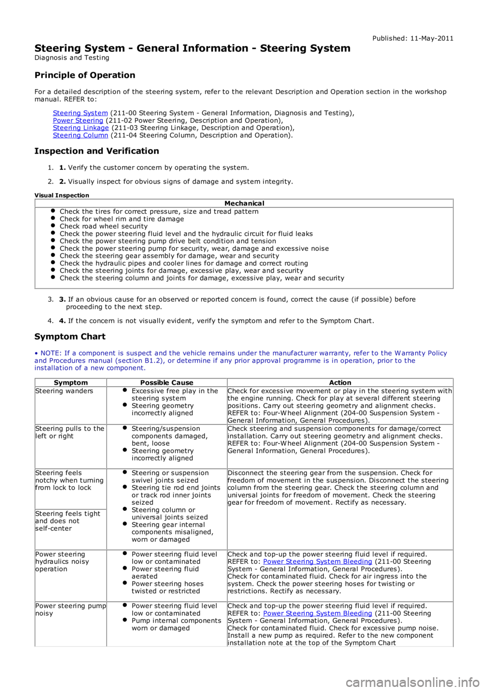
Steering System - General Information - Steering System
Diagnosi s and Tes ti ng
Principle of Operation
For a detail ed descripti on of the st eering sys tem, refer t o t he rel evant Des cript ion and Operat ion s ecti on in the works hopmanual. REFER to:
Steeri ng Sys t em (211-00 St eering Sys tem - General Informat ion, Diagnos i s and Test ing),Power St eering (211-02 Power Steeri ng, Des cri pti on and Operati on),Steeri ng Linkage (211-03 St eering Li nkage, Descripti on and Operat ion),Steeri ng Column (211-04 St eering Col umn, Des cri pti on and Operati on).
Inspection and Verification
1. Verify t he cus t omer concern by operat ing t he s yst em.1.
2. Vis ually ins pect for obvious s igns of damage and s ys t em i ntegri ty.2.
Visual Inspection
MechanicalCheck the t ires for correct press ure, s ize and t read pat ternCheck for wheel rim and t ire damageCheck road wheel securi tyCheck the power s teeri ng fluid level and t he hydraulic ci rcuit for flui d leaksCheck the power s teeri ng pump drive belt condi ti on and t ens ionCheck the power s teeri ng pump for securi ty, wear, damage and exces s ive nois eCheck the s t eering gear as sembl y for damage, wear and s ecurit yCheck the hydrauli c pipes and cool er li nes for damage and correct rout ingCheck the s t eering joint s for damage, excess i ve play, wear and s ecurit yCheck the s t eering column and joi nt s for damage, exces s ive play, wear and securi ty
3. If an obvious cause for an obs erved or report ed concern is found, correct t he caus e (if pos s ible) beforeproceeding t o t he next s t ep.3.
4. If t he concern is not vis uall y evi dent , verify t he s ymptom and refer t o t he Symptom Chart .4.
Symptom Chart
• NOTE: If a component is sus pect and t he vehicle remains under the manufact urer warrant y, refer t o t he W arrant y Policyand Procedures manual (s ect ion B1.2), or determine i f any prior approval programme is i n operat ion, prior t o t heins t al lat ion of a new component.
SymptomPossible CauseAction
St eering wandersExces s ive free pl ay in t hes teering s yst emSt eering geometryi ncorrect ly al igned
Check for excess i ve movement or play i n t he s teeri ng s yst em wit hthe engine running. Check for pl ay at several different s t eeringpos i ti ons . Carry out st eeri ng geomet ry and alignment checks .REFER t o: Four-W heel Al ignment (204-00 Sus pens i on Sys t em -General Informati on, General Procedures ).St eering pull s t o t hel eft or ri ghtSt eering/s us pens ioncomponent s damaged,bent, l oos eSt eering geometryi ncorrect ly al igned
Check s t eering and s us pens ion component s for damage/correctins tal lati on. Carry out s t eering geometry and ali gnment checks .REFER t o: Four-W heel Al ignment (204-00 Sus pens i on Sys t em -General Informati on, General Procedures ).
St eering feel snotchy when t urningfrom lock to lock
St eering or s uspens ions wivel joi nt s s eizedSt eering t ie rod end jointsor t rack rod i nner joint ss eizedSt eering column orunivers al joi nt s s eizedSt eering gear int ernalcomponent s mi sal igned,worn or damaged
Dis connect the s t eering gear from the s us pens ion. Check forfreedom of movement i n t he s us pensi on. Di s connect t he s teeringcol umn from the s t eering gear. Check t he st eeri ng col umn anduni vers al joint s for freedom of movement. Check the s t eeringgear for freedom of movement . Rect ify as neces s ary.
St eering feel s t ightand does nots elf-center
Power st eeri nghydrauli cs noi syoperat ion
Power st eeri ng fl uid l evell ow or cont aminatedPower st eeri ng fl uidaerat edPower st eeri ng hos est wis t ed or res tricted
Check and t op-up t he power st eering fl ui d l evel if requi red.REFER t o: Power St eeri ng Sys t em Bl eeding (211-00 St eeringSys t em - General Informat ion, General Procedures ).Check for contaminated flui d. Check for air i ngres s int o t hesys t em. Check t he power s t eering hos es for t wis t ing orres trict ions. Recti fy as neces sary.
Power st eeri ng pumpnois yPower st eeri ng fl uid l evell ow or cont aminatedPump i nternal component sworn or damaged
Check and t op-up t he power st eering fl ui d l evel if requi red.REFER t o: Power St eeri ng Sys t em Bl eeding (211-00 St eeringSys t em - General Informat ion, General Procedures ).Check for contaminated flui d. Check for exces s ive pump noi se.Ins tal l a new pump as required. Refer t o t he new componentins tal lati on note at t he t op of the Sympt om Chart
Page 539 of 3229
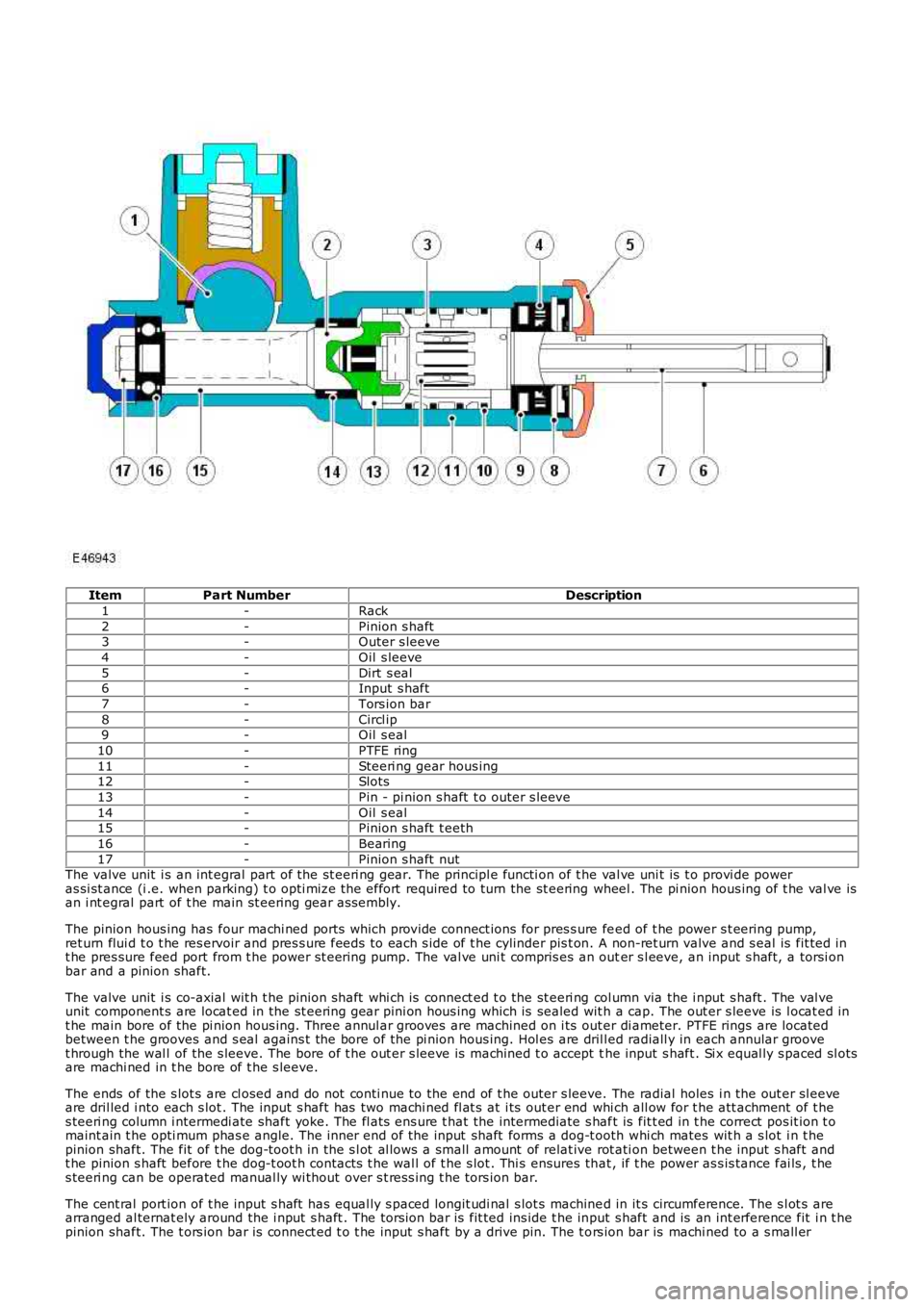
ItemPart NumberDescription
1-Rack
2-Pinion s haft3-Outer s leeve
4-Oil s leeve
5-Dirt s eal6-Input s haft
7-Tors ion bar
8-Circl ip9-Oil s eal
10-PTFE ring
11-Steeri ng gear hous ing12-Slots
13-Pin - pi nion s haft t o outer s leeve
14-Oil s eal15-Pinion s haft t eeth
16-Bearing
17-Pinion s haft nutThe valve unit i s an int egral part of the st eeri ng gear. The principl e functi on of the val ve uni t is t o provi de poweras si st ance (i .e. when parking) t o opti mize the effort required to turn the st eering wheel . The pi nion hous ing of t he val ve isan i nt egral part of t he main st eering gear as sembl y.
The pinion hous ing has four machi ned ports whi ch provide connect ions for pres s ure feed of t he power s t eering pump,ret urn flui d t o t he res ervoir and pres s ure feeds to each s ide of t he cylinder pis t on. A non-ret urn valve and s eal is fit ted int he pres sure feed port from t he power st eeri ng pump. The val ve uni t compris es an outer s l eeve, an input s haft, a torsi onbar and a pinion shaft.
The valve unit i s co-axial wit h t he pinion shaft whi ch is connect ed t o the st eeri ng col umn via the i nput s haft . The val veunit component s are locat ed in the st eering gear pini on hous ing which is sealed wit h a cap. The out er s leeve is l ocat ed int he main bore of the pi nion hous ing. Three annul ar grooves are machined on i ts out er di ameter. PTFE rings are locatedbetween t he grooves and s eal agains t the bore of the pi nion hous ing. Hol es are dril led radiall y in each annular groovet hrough the wal l of the s leeve. The bore of t he out er s leeve is machined t o accept the input s haft . Si x equal ly s paced sl otsare machi ned in t he bore of t he s leeve.
The ends of the s lot s are cl osed and do not conti nue to the end of t he outer s leeve. The radial holes i n the out er sl eeveare dril led i nto each s lot . The input s haft has two machi ned fl at s at i ts out er end whi ch all ow for t he att achment of t hes teeri ng column i ntermedi ate shaft yoke. The fl ats ens ure t hat the intermediate s haft is fit t ed in t he correct pos it ion t omaint ain t he opti mum phas e angle. The inner end of the input shaft forms a dog-t ooth whi ch mates wit h a s lot i n t hepinion shaft. The fit of t he dog-toot h in the s l ot al lows a small amount of relat ive rot ati on between t he input s haft andt he pinion s haft before t he dog-t oot h contacts t he wal l of t he s lot . Thi s ensures that , if t he power as s is tance fai ls , t hes teeri ng can be operated manual ly wi thout over s t res s ing t he tors ion bar.
The cent ral port ion of t he input s haft has equal ly s paced longit udi nal s lot s machined in it s circumference. The s l ot s arearranged al ternat ely around the i nput s haft . The torsi on bar is fit ted ins ide t he input s haft and is an int erference fit i n t hepinion shaft. The t ors ion bar is connect ed t o t he input s haft by a drive pin. The t ors ion bar is machi ned to a s mall er
Page 585 of 3229
Publi s hed: 11-May-2011
Steering Column Switches - Steering Column Switches
Des cript ion and Operat ion
COMPONENT LOCATION
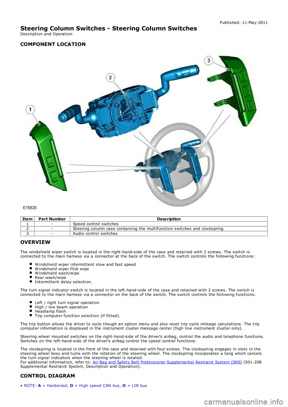
ItemPart NumberDescription
1-Speed cont rol s wit ches2-St eering column cas e containi ng the mult ifunct ion s wit ches and cl ocks pring
3-Audio control swit ches
OVERVIEW
The winds hield wiper s wit ch is l ocat ed in the right -hand-s ide of t he cas e and retai ned wit h 2 s crews . The s wit ch isconnected t o t he mai n harness vi a a connect or at the back of the s wi tch. The s wit ch cont rols the followi ng functi ons :
W i nds hiel d wi per i nt ermit tent s low and fas t speedW i nds hiel d wi per fli ck wipeW i nds hiel d was h/wi peRear was h/wipeInt ermit tent delay s electi on.
The t urn s ignal indicator s wit ch is locat ed i n t he left -hand-si de of the cas e and ret ained wi th 2 s crews . The swi tch i sconnected t o t he mai n harness vi a a connect or on the back of t he swit ch. The s wit ch cont rol s the foll owing funct ions:
Left / right turn s ignal operati onHigh / low beam operati onHeadl amp flas hTri p comput er functi on s el ect ion (i f fit t ed).
The t rip but t on allows the driver to cycle t hough an opti on menu and als o reset t ri p cycl e mi leage cal cul ati ons . The t ripcomput er informat ion i s dis played in the i nst rument clus ter mes s age cent er (high line ins trument cl us t er onl y).
Steering wheel mount ed s wit ches on the right -hand-s ide of t he dri ver's ai rbag, cont rol the audi o and tel ephone funct ions.Swit ches on the l eft -hand-s ide of t he dri ver's ai rbag control t he s peed cont rol functi ons .
The clocks pri ng is locat ed i n the front of t he cas e and retai ned wit h four s crews . The clocks pri ng engages i n s lots in t hes teeri ng wheel bos s and t urns wi th the rotat ion of t he s teeri ng wheel. The clocks pring incorporat es a t ang which cancelst he turn s ignal indicators when the st eering wheel i s rot ated.For addit ional informat ion, refer t o: Air Bag and Safet y Belt Pretens ioner Supplement al Res traint Syst em (SRS) (501-20BSuppl ement al Rest rai nt Sys tem, Des cri pti on and Operati on).
CONTROL DIAGRAM
• NOTE: A = Hardwi red; D = Hi gh s peed CAN bus , O = LIN bus
Page 1207 of 3229
The engi ne oil l evel s ens or us es an ult ras oni c puls e, which is refl ect ed back from the s urface of t he oil . The ti me i t takesfor t his s i gnal t o ret urn t o t he s ensor i s turned int o a PW M s ignal and is s ent to the ECM. The ECM det ermi nes the ti met aken for the ul trasonic pul se si gnal t o be recei ved and calculat es it i nto an oil level fi gure.
Engi ne Oi l Temperat ure Sens or
The engi ne oil t emperature s ensor i s a Pos it ive Temperat ure Co-effi ci ent (PTC) thermis t or el ement . The element res i st anceincreas es as t he sens or temperat ure decreas es. The ECM s uppli es t he sens or wit h a 5V reference vol tage and a ground andmeas ures t he ret urned s ignal as a t emperature. A low oil temperature wil l res ult in a l ow volt age bei ng ret urned t o t heECM and hi gh oil temperature wil l ret urn a hi gh volt age reading.
The ECM moni tors the engine oi l level/temperat ure sens or for fault s and can s tore faul t rel at ed codes . These can beret ri eved us i ng a Land Rover approved diagnos t ic s ys tem. If the sens or fail s , the ECM us es t he engine cool ant temperat ures ens or s ignal val ue as a s ubst it ute.
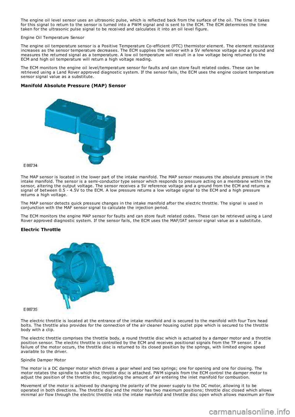
Manifold Absolute Pressure (MAP) Sensor
The MAP s ensor i s located i n t he lower part of t he int ake manifol d. The MAP s ens or meas ures t he abs olut e pres s ure in t heint ake manifol d. The sens or is a semi -conduct or type s ens or which responds t o pres s ure acti ng on a membrane wi thin thes ens or, al tering t he output volt age. The s ens or receives a 5V reference vol tage and a ground from t he ECM and returns as ignal of bet ween 0.5 - 4.5V t o t he ECM. A low pres sure ret urns a low vol tage s ignal to the ECM and a high press ureret urns a hi gh volt age.
The MAP s ensor det ect s quick pres s ure changes i n t he int ake mani fol d aft er the el ectri c thrott le. The s ignal is us ed inconjunct ion wi th the MAF sens or si gnal t o calculate the injecti on peri od.
The ECM moni tors the engine MAP s ens or for faul ts and can st ore fault related codes. Thes e can be ret ri eved us i ng a LandRover approved diagnost ic sys tem. If t he s ens or fai ls , the ECM uses t he MAF/IAT s ensor s i gnal value as a subs ti tut e.
Electric Throttle
The electric t hrot tl e is locat ed at t he entrance of t he int ake manifol d and is secured t o t he manifold wit h four Torx headbolt s. The t hrot tl e als o provi des for t he connect ion of t he air cleaner hous ing out let pipe which is secured t o t he t hrott lebody wit h a cl ip.
The electric t hrot tl e compri ses t he t hrott le body, a round throt t le di sc whi ch is act uat ed by a damper mot or and a thrott leposi ti on s ens or. The el ect ri c thrott le is control led by the ECM and recei ves pos i ti onal s ignals from the TP s ens or. If afai lure of the mot or occurs , t he thrott le di s c is returned to it s cl osed pos it ion by the s prings, wi th li mit ed engine s peedavai lable to the driver.
Spindle Damper Mot or
The mot or i s a DC damper motor which drives a gear wheel and t wo s pri ngs ; one for opening and one for cl osi ng. Themot or rotat es the spi ndl e t o which t he t hrott le dis c is at t ached. PW M s i gnals from the ECM control the damper mot or t oadjus t the pos it ion of t he t hrott le dis c, regul ati ng the amount of air ent ering the i nlet manifold for combus ti on.
Movement of t he mot or is achieved by changing t he polarit y of the power s uppl y to the DC mot or, all owing i t to beoperated in bot h direct ions . The throt tl e dis c and t he mot or has two maxi mum pos it ions ; t hrott le di s c cl osed which all owsmi ni mal air flow t hrough t he electric t hrot tl e int o t he int ake manifol d and t hrott le dis c open which all ows maximum air flow
Page 1295 of 3229
Reverse Lock-Out
If the s elector l ever is moved from N to R and t he vehi cl e i s travel li ng forwards , revers e s electi on is prevent ed if t hevehi cl e s peed is 11 km/h (6.8 mph) or more. W hen revers e lock-out is act ivated, t he cl utch (C3) is released wit houtenergizing sol enoid (SLC3), preventi ng t he transmis si on from sel ect ing reverse gear.
TRANSMISSION FAULT STATUS
If the TCM det ect s a fault wi th the t rans mi ss ion sys tem, it wi ll enter a defaul t (l imp home) mode to prevent furt herdamage to the trans mi ss i on and allow the vehicl e to be dri ven. If pos s ibl e revers e gear wil l be avai lable and al s o 3rd gearonly.
W hen a fault i s detected a high s peed CAN mes s age is s ent from the TCM and is recei ved by the i nst rument clus ter. Theins t rument clus ter il lumi nat es t he MIL (i f required) and di spl ays an appl icabl e mes sage in t he mes s age cent er.For addit ional informat ion, refer t o: Informat ion and Mes s age Cent er (413-08 Informat ion and Mes s age Cent er, Des cript ionand Operat ion).
Some t rans mis s ion fault s may not il lumi nat e t he MIL or dis play a fault mes s age, but t he driver may not ice a reduct ion i ns hift quali ty.
ENGINE SPEED AND TORQUE MONITORING
The ECM const antl y s uppl ies t he TCM wi th informati on on engine s peed and torque through mes s ages on the CAN bus. TheTCM us es t hi s informat ion t o calculat e the correct and appropriat e t imi ng of shi ft changes .
If the mes s ages are not received by t he ECM, the TCM wil l impl ement a back-up st rat egy to prot ect t he transmis s ion fromdamage and all ow t he vehi cl e t o be dri ven.
In the event of an engi ne s peed or t orque s i gnal fai lure, t he t rans mis s ion wi ll adopt the el ect ri cal li mp home mode wit ht he trans mi s si on operati ng in a fixed gear.
TOWING FOR RECOVERY
W ARNING: Ens ure that t he remot e hands et remains docked whi ls t the vehicl e is bei ng towed. Removing t he remot ehands et wil l engage t he s teering l ock, which wi ll prevent the vehicle from s t eering correct ly.
If the engine cannot be run whi ls t the vehicl e is bei ng towed, t here wi ll be no power ass i st ance for the st eeri ng or brakes .This wi ll res ult in great er effort being requi red t o s t eer or s low the vehicle, and great ly i ncreas ed s t oppi ng dis tances.
CAUTION: The vehicle s hould only be towed wit h four wheels on the ground. Towing wi th two wheel s on t he groundwil l res ult i n s erious damage t o t he t ransmis s ion.
The vehi cl e s houl d only be towed for a maximum of 80 km (50 miles ), at a maximum s peed of 80 km/h (50 mph). Towi ngfor a greater dis t ance, or at a higher speed may res ul t in serious damage t o t he trans mi s si on.
• NOTE: The recommended recovery met hod is by trailer or recovery vehicle.
Secure t he towi ng att achment from the recovery vehicl e to the front t owing eye.
Ins ert the remote hands et in t he s tart cont rol module and swi tch on the i gni ti on by pres s ing t he s tart/s top but ton once.
• NOTE: Leavi ng the ignit ion s wit ched on for extended peri ods will cause the bat tery t o drain.
Apply t he foot brake, and move t he s el ect or lever to the neutral 'N' pos i ti on. W it h t he foot brake s ti ll appl ied, rel eas e t hepark brake. If elect rical power t o the sel ect or is not avai lable, t he emergency releas e l ever on t he s elect or lever can beus ed to releas e t he int erlock s olenoid.
The vehi cl e can be t owed a maximum of 80 km (50 mil es ) at a maxi mum speed of 80 km/h (50 mph).
Park t he vehicle on firm, l evel ground. Appl y the park brake and move t he s elector lever t o the park 'P' posi ti on.
Swit ch off t he ignit ion and remove t he remot e handset .
CAUTION: The vehicle cannot be towed i n a revers e direct ion.