LEXUS LS430 2003 Factory Repair Manual
LS430 2003
LEXUS
LEXUS
https://www.carmanualsonline.info/img/36/57050/w960_57050-0.png
LEXUS LS430 2003 Factory Repair Manual
Page 3318 of 4500
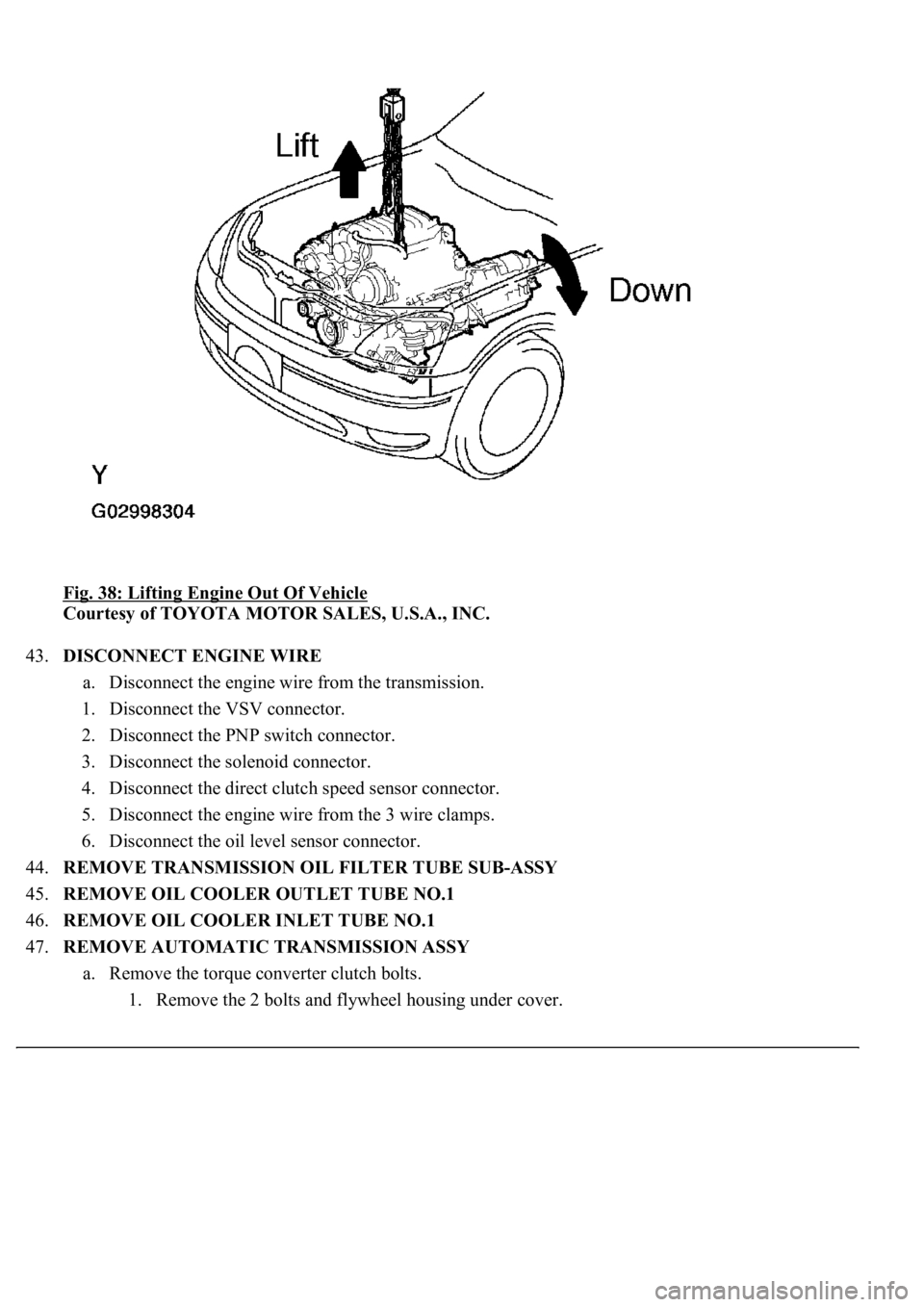
Fig. 38: Lifting Engine Out Of Vehicle
Courtesy of TOYOTA MOTOR SALES, U.S.A., INC.
43.DISCONNECT ENGINE WIRE
a. Disconnect the engine wire from the transmission.
1. Disconnect the VSV connector.
2. Disconnect the PNP switch connector.
3. Disconnect the solenoid connector.
4. Disconnect the direct clutch speed sensor connector.
5. Disconnect the engine wire from the 3 wire clamps.
6. Disconnect the oil level sensor connector.
44.REMOVE TRANSMISSION OIL FILTER TUBE SUB-ASSY
45.REMOVE OIL COOLER OUTLET TUBE NO.1
46.REMOVE OIL COOLER INLET TUBE NO.1
47.REMOVE AUTOMATIC TRANSMISSION ASSY
a. Remove the torque converter clutch bolts.
1. Remove the 2 bolts and fl
ywheel housing under cover.
Page 3319 of 4500
2. Turn the crankshaft damper bolt to gain access to each bolt.
3. Hold the crankshaft damper bolt with a wrench, and remove the 6 bolts.
b. Remove the 10 bolts and ground strap.
c. Remove the transmission together with the torque converter clutch from the engine.
Fig. 39: Removing Flywheel Housing Under Cover
Courtesy of TOYOTA MOTOR SALES, U.S.A., INC.
48.REMOVE DRIVE PLATE & RING GEAR SUB-ASSY
a. Remove the 8 bolts, rear spacer, ring gear and front spacer.
49.INSTALL ENGINE STAND
50.REMOVE THROTTLE BODY ASSY (See REPLACEMENT
)
51.REMOVE INTAKE MANIFOLD ASSY
a. Disconnect the VSV connector for EVAP.
b. Disconnect the EVAP hose from the VSV for EVAP.
c. Remove the bolt, disconnect the VSV for EVAP from the upper intake manifold.
d. Remove the bolt and V-bank cover bracket No. 2.
e. Remove the bolt and V-
bank cover bracket No. 3.
Page 3351 of 4500
Fig. 71: Installing Automatic Transmission Assy
Courtesy of TOYOTA MOTOR SALES, U.S.A., INC.
d. Install the torque converter clutch bolts.
1. Apply adhesive to 2 or 3 threads of the bolt end.
Adhesive:
Part No. 08833-00070, THREE BOND 1324 or equivalent
2. Hold the crankshaft pulley bolt with a wrench, and install the 6 bolts evenly.
Torque: 48 N.m (490 kgf.cm, 35 ft.lbf)
HINT:
First install the black colored bolt, and then install the other bolts.
3. Install the flywheel housing undercover with the 2 bolts.
Torque: 18 N.m (184 kgf.cm, 13 ft.lbf)
Page 3361 of 4500
140.INSTALL ENGINE UNDER COVER NO.2
141.INSTALL ENGINE UNDER COVER NO.1
142.INSTALL FRONT WHEEL
143.INSTALL AIR CLEANER ASSY
144.INSTALL INTAKE AIR CONNECTOR PIPE
145.INSTALL AIR CLEANER INLET NO.1
146.INSTALL V-BANK COVER
147.INSTALL HOOD SUB-ASSY (See ADJUSTMENT
and OVERHAUL )
148.CONNECT BATTERY NEGATIVE TERMINAL
149.ADD AUTOMATIC TRANSMISSION FLUID
150.ADD ENGINE COOLANT (See REPLACEMENT
)
151.ADD ENGINE OIL (See ON
-VEHICLE INSPECTION )
152.ADD POWER STEERING FLUID
153.BLEED POWER STEERING FLUID
154.INSPECT AUTOMATIC TRANSMISSION FLUID (See ADJUSTMENT
)
155.INSPECT ENGINE OIL LEAKS
156.CHECK FOR ENGINE COOLANT LEAKS
157.INSPECT FOR FUEL LEAKS
158.CHECK FOR EXHAUST GAS LEAKS
159.INSPECT AND ADJUST FRONT WHEEL ALIGNMENT
160.INSPECT IGNITION TIMING
161.INSPECT ENGINE IDLE SPEED
162.INSPECT CO/HC
163.ADJUST ENGINE (See INSPECTION
)
164.CHECK ABS SPEED SENSOR SIGNAL (See TEST MODE PROCEDURE
)
OVERHAUL
1.REMOVE SPARK PLUG
2.REMOVE OIL FILLER CAP SUB-ASSY
3.REMOVE CYLINDER HEAD COVER SUB-ASSY LH
a. Remove the 9 bolts, 9 seal washers, cylinder head cover and gasket.
4.REMOVE CYLINDER HEAD COVER SUB-ASSY
a. Remove the 9 bolts, 9 seal washers, c
ylinder head cover and gasket.
Page 3877 of 4500
Fig. 88: Removing And Installing Wheel Opening Molding
Courtesy of TOYOTA MOTOR SALES, U.S.A., INC.
REPLACEMENT
HINT:
The installation procedures are the removal procedures in reverse order.
Use the same procedures for the RH side and LH side.
The procedures listed below are for the LH side.
1.REMOVE FRONT FENDER WHEEL OPENING MOLDING LH
a. Remove the 4 screws and molding.
Page 3878 of 4500
Fig. 89: Removing Front Fender Wheel Opening Molding LH
Courtesy of TOYOTA MOTOR SALES, U.S.A., INC.
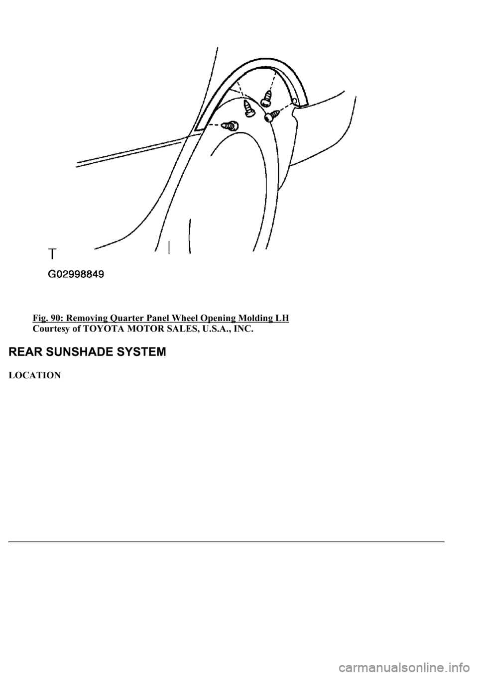
2.REMOVE QUARTER PANEL WHEEL OPENING MOLDING LH
a. Remove the 4 screws and molding.
Page 3879 of 4500
Fig. 90: Removing Quarter Panel Wheel Opening Molding LH
Courtesy of TOYOTA MOTOR SALES, U.S.A., INC.
LOCATION
Page 3999 of 4500
Fig. 7: Measuring Vehicle Height
Courtesy of TOYOTA MOTOR SALES, U.S.A., INC.
Except air suspension:
EXCEPT AIR SUSPENSION
Air suspension:
AIR SUSPENSION
Measuring points:
A.Ground clearance of lower suspension arm No. 1 bushing set bolt center
B.Ground clearance of front wheel center
C.Ground clearance of rear suspension arm No. 2 set bolt center
D.Ground clearance of rear wheel center
Tire SizeFront B-ARear D-C
P225/55R17105 mm (4.13 in.)91 mm (3.58 in.)
245/45R18104 mm (4.09 in.)89 mm (3.50 in.)
Front B-ARear D-C
115 mm (4.53 in.)109 mm (4.29 in.)
Page 4002 of 4500
g. Perform the zero point calibration of yaw rate and deceleration sensor (see CALIBRATION ).
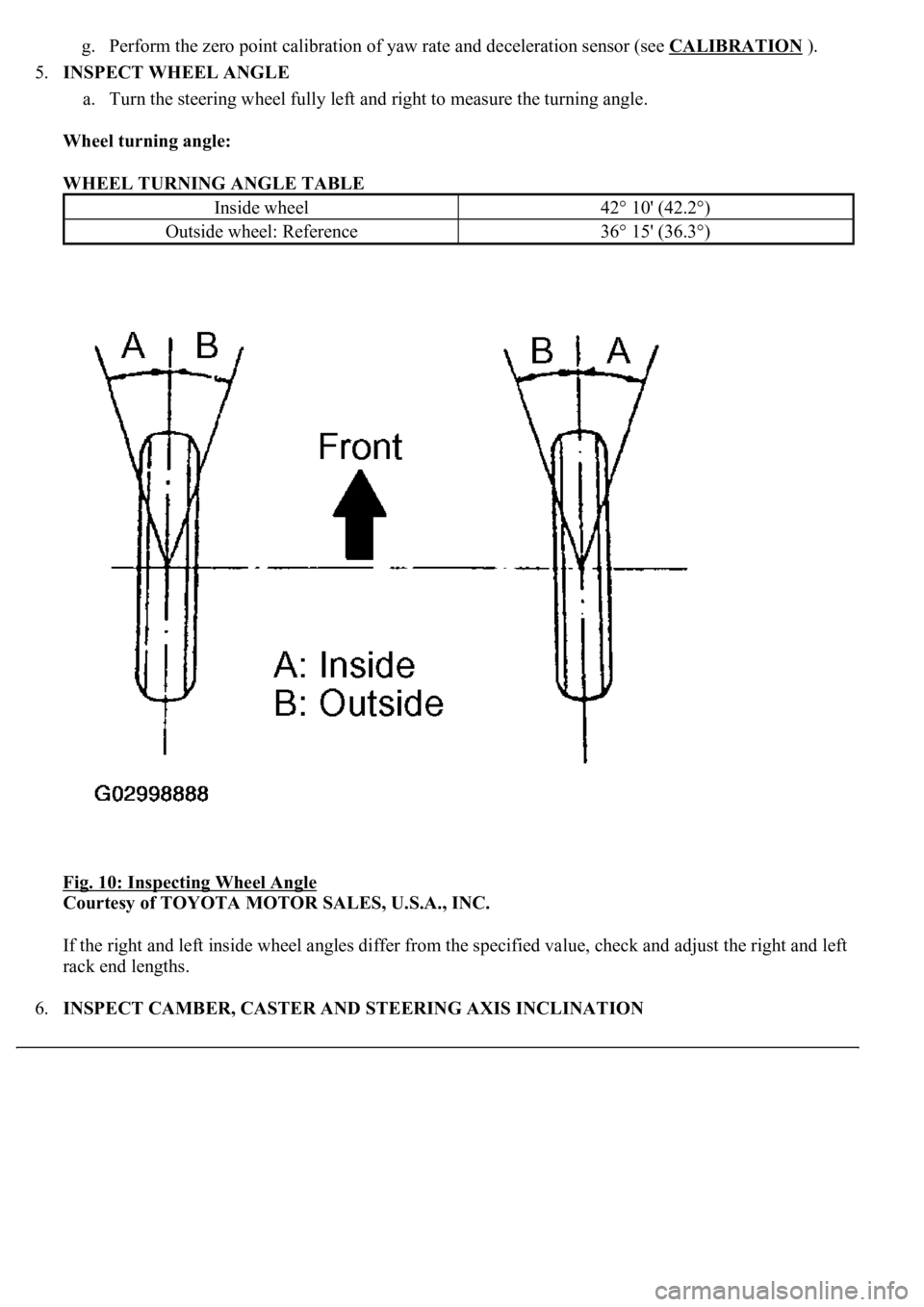
5.INSPECT WHEEL ANGLE
a. Turn the steering wheel fully left and right to measure the turning angle.
Wheel turning angle:
WHEEL TURNING ANGLE TABLE
Fig. 10: Inspecting Wheel Angle
Courtesy of TOYOTA MOTOR SALES, U.S.A., INC.
If the right and left inside wheel angles differ from the specified value, check and adjust the right and left
rack end lengths.
6.INSPECT CAMBER, CASTER AND STEERING AXIS INCLINATION
Inside wheel42° 10' (42.2°)
Outside wheel: Reference36° 15' (36.3°)
Page 4003 of 4500
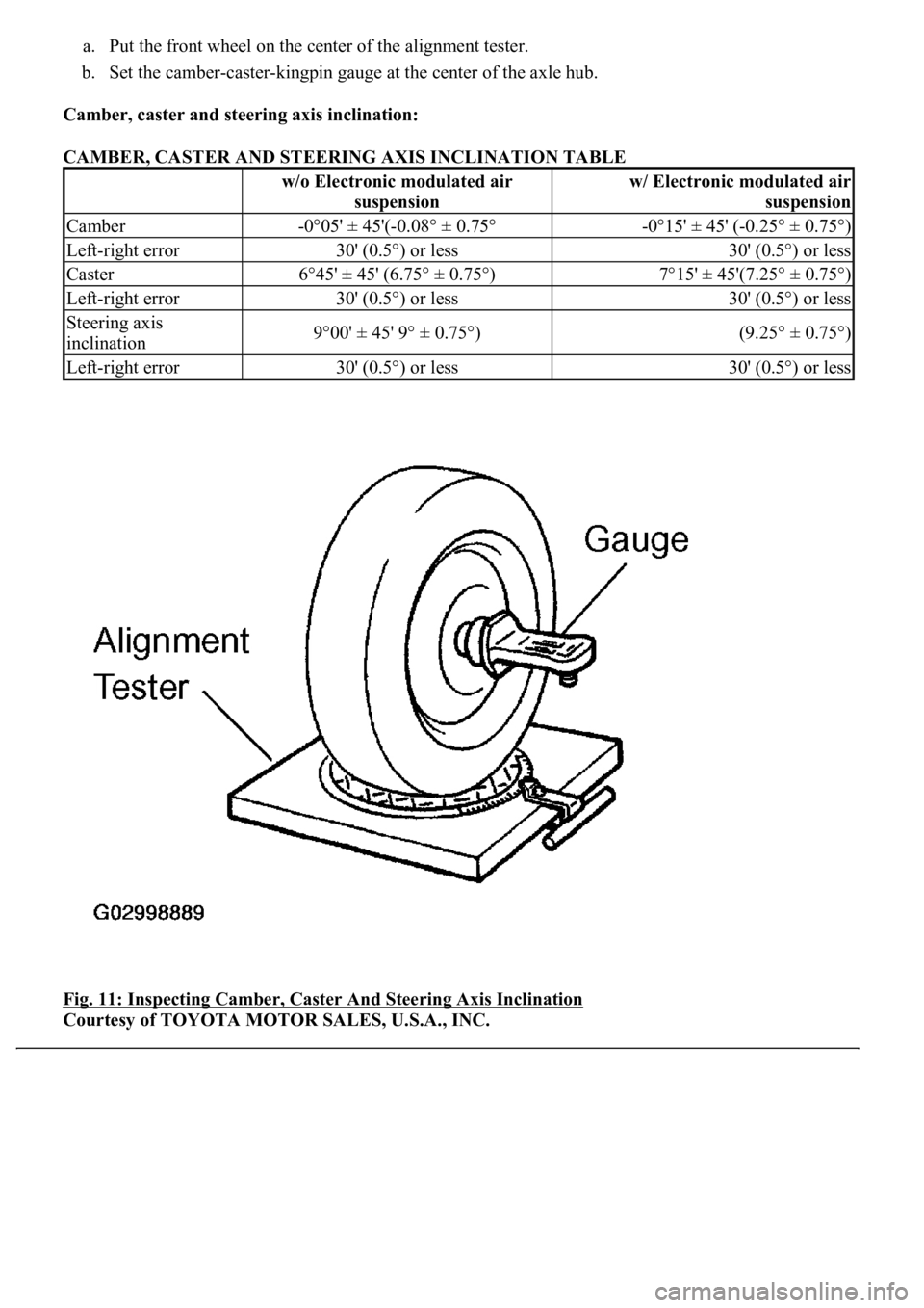
a. Put the front wheel on the center of the alignment tester.
b. Set the camber-caster-kingpin gauge at the center of the axle hub.
Camber, caster and steering axis inclination:
CAMBER, CASTER AND STEERING AXIS INCLINATION TABLE
Fig. 11: Inspecting Camber, Caster And Steering Axis Inclination
Courtesy of TOYOTA MOTOR SALES, U.S.A., INC.
w/o Electronic modulated air
suspensionw/ Electronic modulated air
suspension
Camber-0°05' ± 45'(-0.08° ± 0.75°-0°15' ± 45' (-0.25° ± 0.75°)
Left-right error30' (0.5°) or less30' (0.5°) or less
Caster6°45' ± 45' (6.75° ± 0.75°)7°15' ± 45'(7.25° ± 0.75°)
Left-right error30' (0.5°) or less30' (0.5°) or less
Steering axis
inclination9°00' ± 45' 9° ± 0.75°)(9.25° ± 0.75°)
Left-right error30' (0.5°) or less30' (0.5°) or less