wheel LEXUS LS430 2003 Factory Manual PDF
[x] Cancel search | Manufacturer: LEXUS, Model Year: 2003, Model line: LS430, Model: LEXUS LS430 2003Pages: 4500, PDF Size: 87.45 MB
Page 1150 of 4500
Use the same procedures for the parking brake cable assy No.2 and No.3.
The procedures listed below are for the parking brake cable assy No.3.
1.REMOVE REAR WHEEL
2.SEPARATE REAR DISC BRAKE CALIPER ASSY LH
a. Remove the 2 bolts and separate the rear disc brake caliper assy LH.
HINT:
Do not disconnect the flexible hose from the rear disc brake caliper assy LH.
Do not twist or bend the rear brake caliper assy LH.
b. Hang the rear brake caliper assy LH with a piece of wire.
Fig. 175: Removing Bolts And Separate Rear Disc Brake Caliper Assy LH
Courtesy of TOYOTA MOTOR SALES, U.S.A., INC.
3.REMOVE REAR DISC
a. Place matchmarks on the disc and rear axle hub.
Page 1151 of 4500

b. Remove the disc.
HINT:
If the disc cannot be removed easily, turn the shoe adjuster until the wheel turns smoothly.
Fig. 176: Identifying Matchmarks On Disc And Rear Axle Hub
Courtesy of TOYOTA MOTOR SALES, U.S.A., INC.
4.REMOVE PARKING BRAKE SHOE RETURN TENSION SPRING
a. Using SST, remove the brake shoe return tension spring.
SST 09703-30010
Page 1168 of 4500
j.INSTALL REAR WHEEL
Torque: 103 N.m (1,050 kgf.cm, 76 ft.lbf)
k.INSTALL FRONT FLOOR HEAT INSULATOR NO.1 (SEE REPLACEMENT
)
l.INSTALL EXHAUST PIPE ASSY (SEE REPLACEMENT
)
m.INSTALL OXYGEN SENSOR (SEE REPLACEMENT
)
n.SETTLING PARKING BRAKE SHOES AND DISC
a. Drive the vehicle at approximately 50 km/h (31 mph) on a safe, level and dry road.
b. Depress the parking brake pedal with a force of 150 N (15 kgf.cm, 34 lbf).
c. Drive the vehicle for approximately 400 meters (0.25 mile) in this condition.
d. Repeat this procedure 2 or 3 times.
o.CHECK PARKING BRAKE PEDAL TRAVEL (SEE ADJUSTMENT
)
p.ADJUST PARKING BRAKE PEDAL TRAVEL (SEE ADJUSTMENT
)
COMPONENTS
Page 1170 of 4500
Use the same procedures for the RH side and LH side.
The procedures listed below are for the LH side.
1.REMOVE REAR WHEEL
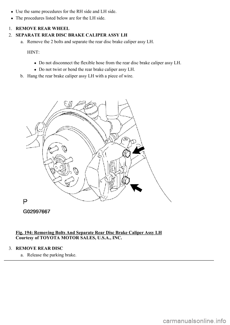
2.SEPARATE REAR DISC BRAKE CALIPER ASSY LH
a. Remove the 2 bolts and separate the rear disc brake caliper assy LH.
HINT:
Do not disconnect the flexible hose from the rear disc brake caliper assy LH.
Do not twist or bend the rear brake caliper assy LH.
b. Hang the rear brake caliper assy LH with a piece of wire.
Fig. 194: Removing Bolts And Separate Rear Disc Brake Caliper Assy LH
Courtesy of TOYOTA MOTOR SALES, U.S.A., INC.
3.REMOVE REAR DISC
a. Release the parkin
g brake.
Page 1171 of 4500

b. Place matchmarks on the disc and rear axle hub.
c. Remove the disc.
HINT:
If the disc cannot be removed easily, turn the shoe adjuster until the wheel turns smoothly.
Fig. 195: Identifying Matchmarks On Disc And Rear Axle Hub
Courtesy of TOYOTA MOTOR SALES, U.S.A., INC.
4.MEASURE BRAKE DISC INSIDE DIAMETER
Using a brake drum gauge or equivalent, measure the inside diameter of the disc.
Standard inside diameter: 190 mm (7.48 in.)
Maximum inside diameter: 191 mm (7.52 in.)
Replace the disc if the inside diameter is at the maximum value or more. Replace the disc or grind it with
a lathe if the disc is scored or worn unevenly.
Page 1190 of 4500

23.INSTALL REAR WHEEL
Torque: 103 N.m (1,050 kgf.cm, 76 ft.lbf)
24.SETTLING PARKING BRAKE SHOES AND DISC
a. Drive the vehicle at approximately 50 km/h (31 mph) on a safe, level and dry road.
b. Depress the parking brake pedal with a force of 150 N (15 kgf, 34 lbf).
c. Drive the vehicle for approximately 400 meters (0.25 mile) in this condition.
d. Repeat this procedure 2 or 3 times.
25.CHECK PARKING BRAKE PEDAL TRAVEL (SEE ADJUSTMENT
)
26.ADJUST PARKING BRAKE PEDAL TRAVEL (SEE ADJUSTMENT
)
Page 1743 of 4500
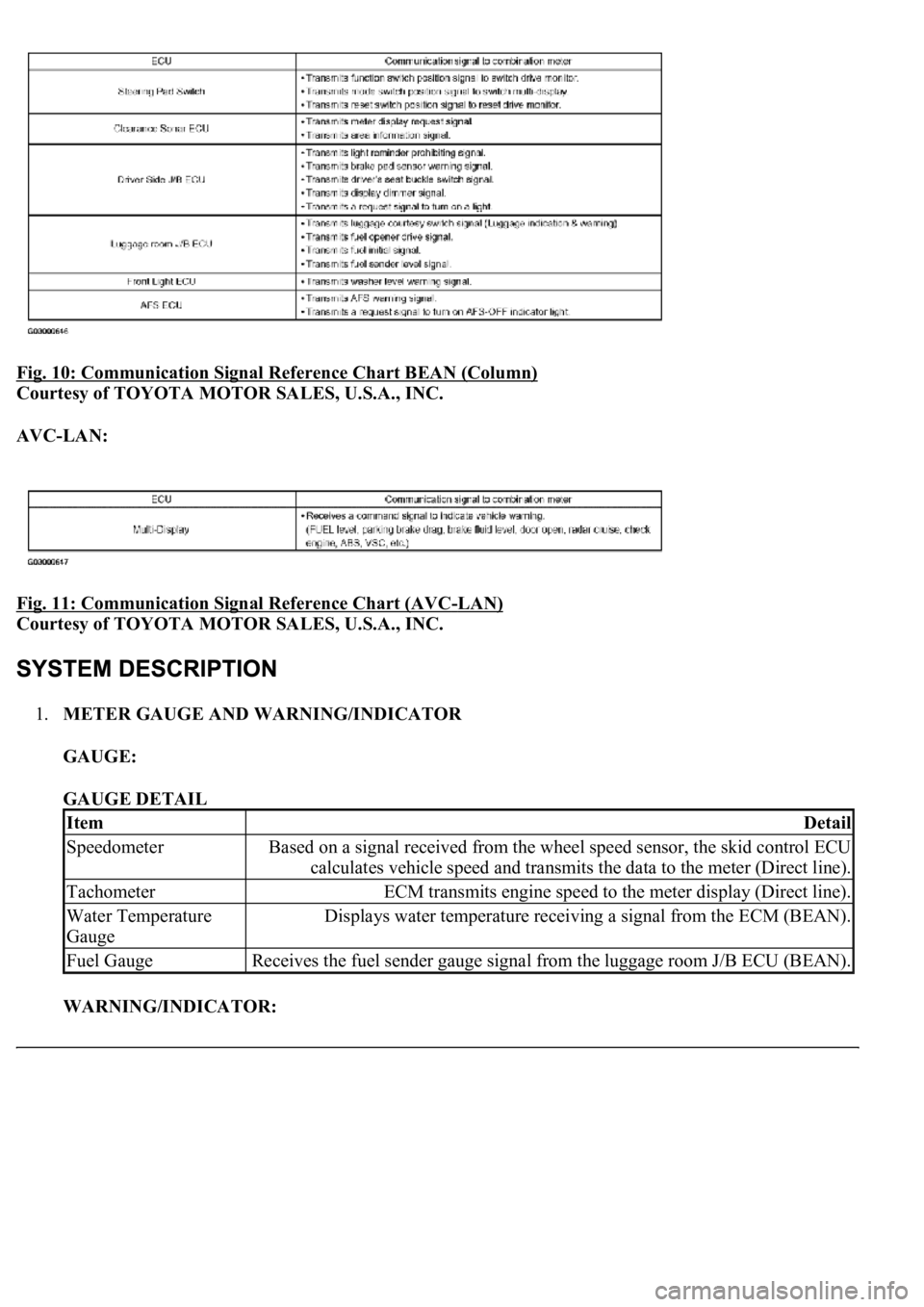
Fig. 10: Communication Signal Reference Chart BEAN (Column)
Courtesy of TOYOTA MOTOR SALES, U.S.A., INC.
AVC-LAN:
Fig. 11: Communication Signal Reference Chart (AVC
-LAN)
Courtesy of TOYOTA MOTOR SALES, U.S.A., INC.
1.METER GAUGE AND WARNING/INDICATOR
GAUGE:
GAUGE DETAIL
WARNING/INDICATOR:
ItemDetail
SpeedometerBased on a signal received from the wheel speed sensor, the skid control ECU
calculates vehicle speed and transmits the data to the meter (Direct line).
TachometerECM transmits engine speed to the meter display (Direct line).
Water Temperature
GaugeDisplays water temperature receiving a signal from the ECM (BEAN).
Fuel GaugeReceives the fuel sender gauge signal from the luggage room J/B ECU (BEAN).
Page 1763 of 4500
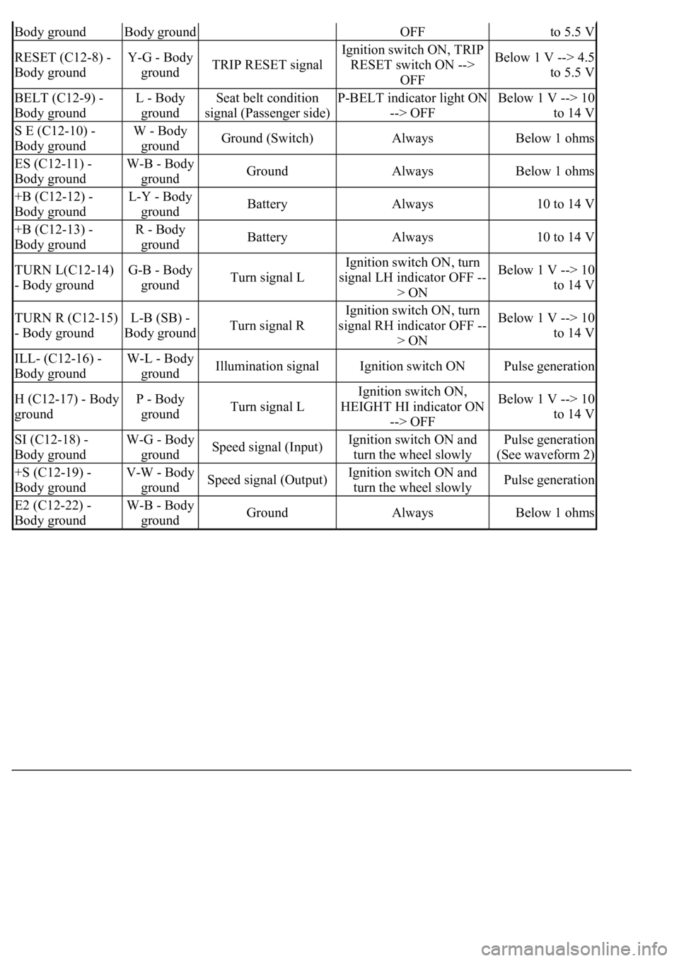
Body groundBody groundOFFto 5.5 V
RESET (C12-8) -
Body groundY-G - Body
groundTRIP RESET signal
Ignition switch ON, TRIP
RESET switch ON -->
OFFBelow 1 V --> 4.5
to 5.5 V
BELT (C12-9) -
Body groundL - Body
groundSeat belt condition
signal (Passenger side)P-BELT indicator light ON
--> OFFBelow 1 V --> 10
to 14 V
S E (C12-10) -
Body groundW - Body
groundGround (Switch)AlwaysBelow 1 ohms
ES (C12-11) -
Body groundW-B - Body
groundGroundAlwaysBelow 1 ohms
+B (C12-12) -
Body groundL-Y - Body
groundBatteryAlways10 to 14 V
+B (C12-13) -
Body groundR - Body
groundBatteryAlways10 to 14 V
TURN L(C12-14)
- Body groundG-B - Body
groundTurn signal L
Ignition switch ON, turn
signal LH indicator OFF --
> ONBelow 1 V --> 10
to 14 V
TURN R (C12-15)
- Body groundL-B (SB) -
Body groundTurn signal R
Ignition switch ON, turn
signal RH indicator OFF --
> ONBelow 1 V --> 10
to 14 V
ILL- (C12-16) -
Body groundW-L - Body
groundIllumination signalIgnition switch ONPulse generation
H (C12-17) - Body
groundP - Body
groundTurn signal L
Ignition switch ON,
HEIGHT HI indicator ON
--> OFFBelow 1 V --> 10
to 14 V
SI (C12-18) -
Body groundW-G - Body
groundSpeed signal (Input)Ignition switch ON and
turn the wheel slowlyPulse generation
(See waveform 2)
+S (C12-19) -
Body groundV-W - Body
groundSpeed signal (Output)Ignition switch ON and
turn the wheel slowlyPulse generation
E2 (C12-22) -
Body groundW-B - Body
groundGroundAlwaysBelow 1 ohms
Page 1948 of 4500
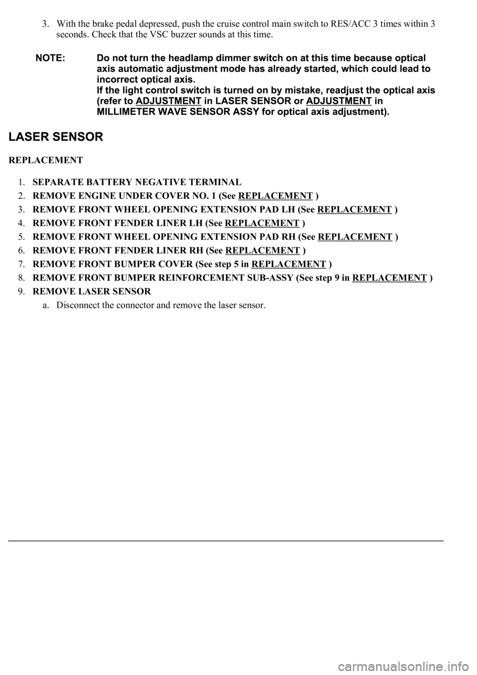
3. With the brake pedal depressed, push the cruise control main switch to RES/ACC 3 times within 3
seconds. Check that the VSC buzzer sounds at this time.
REPLACEMENT
1.SEPARATE BATTERY NEGATIVE TERMINAL
2.REMOVE ENGINE UNDER COVER NO. 1 (See REPLACEMENT
)
3.REMOVE FRONT WHEEL OPENING EXTENSION PAD LH (See REPLACEMENT
)
4.REMOVE FRONT FENDER LINER LH (See REPLACEMENT
)
5.REMOVE FRONT WHEEL OPENING EXTENSION PAD RH (See REPLACEMENT
)
6.REMOVE FRONT FENDER LINER RH (See REPLACEMENT
)
7.REMOVE FRONT BUMPER COVER (See step 5 in REPLACEMENT
)
8.REMOVE FRONT BUMPER REINFORCEMENT SUB-ASSY (See step 9 in REPLACEMENT
)
9.REMOVE LASER SENSOR
a. Disconnect the connector and remove the laser sensor.
Page 1986 of 4500
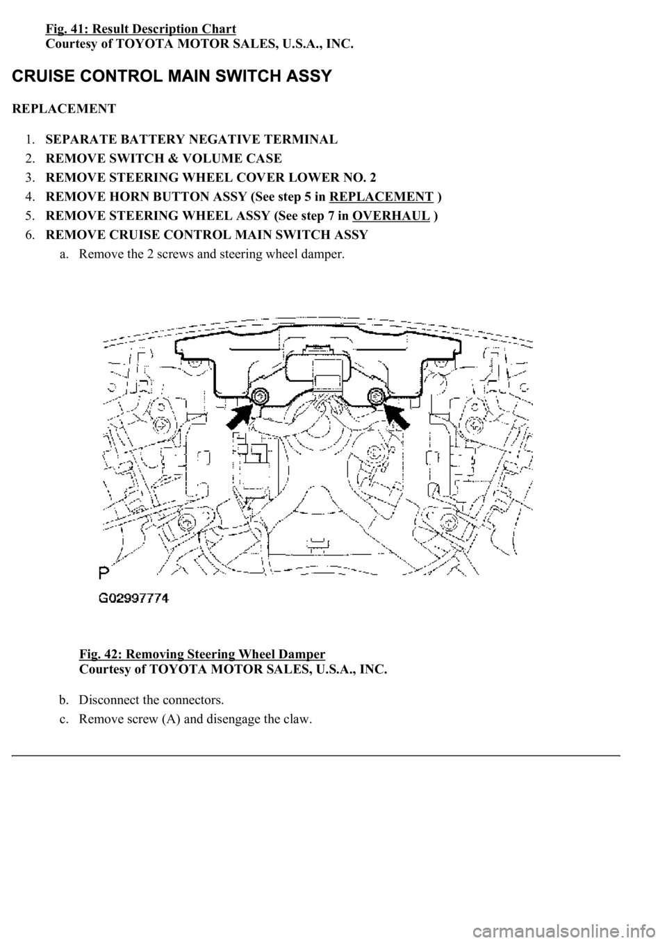
Fig. 41: Result Description Chart
Courtesy of TOYOTA MOTOR SALES, U.S.A., INC.
REPLACEMENT
1.SEPARATE BATTERY NEGATIVE TERMINAL
2.REMOVE SWITCH & VOLUME CASE
3.REMOVE STEERING WHEEL COVER LOWER NO. 2
4.REMOVE HORN BUTTON ASSY (See step 5 in REPLACEMENT
)
5.REMOVE STEERING WHEEL ASSY (See step 7 in OVERHAUL
)
6.REMOVE CRUISE CONTROL MAIN SWITCH ASSY
a. Remove the 2 screws and steering wheel damper.
Fig. 42: Removing Steering Wheel Damper
Courtesy of TOYOTA MOTOR SALES, U.S.A., INC.
b. Disconnect the connectors.
c. Remove screw (A) and disengage the claw.