park LEXUS LS430 2003 Factory Repair Manual
[x] Cancel search | Manufacturer: LEXUS, Model Year: 2003, Model line: LS430, Model: LEXUS LS430 2003Pages: 4500, PDF Size: 87.45 MB
Page 2729 of 4500
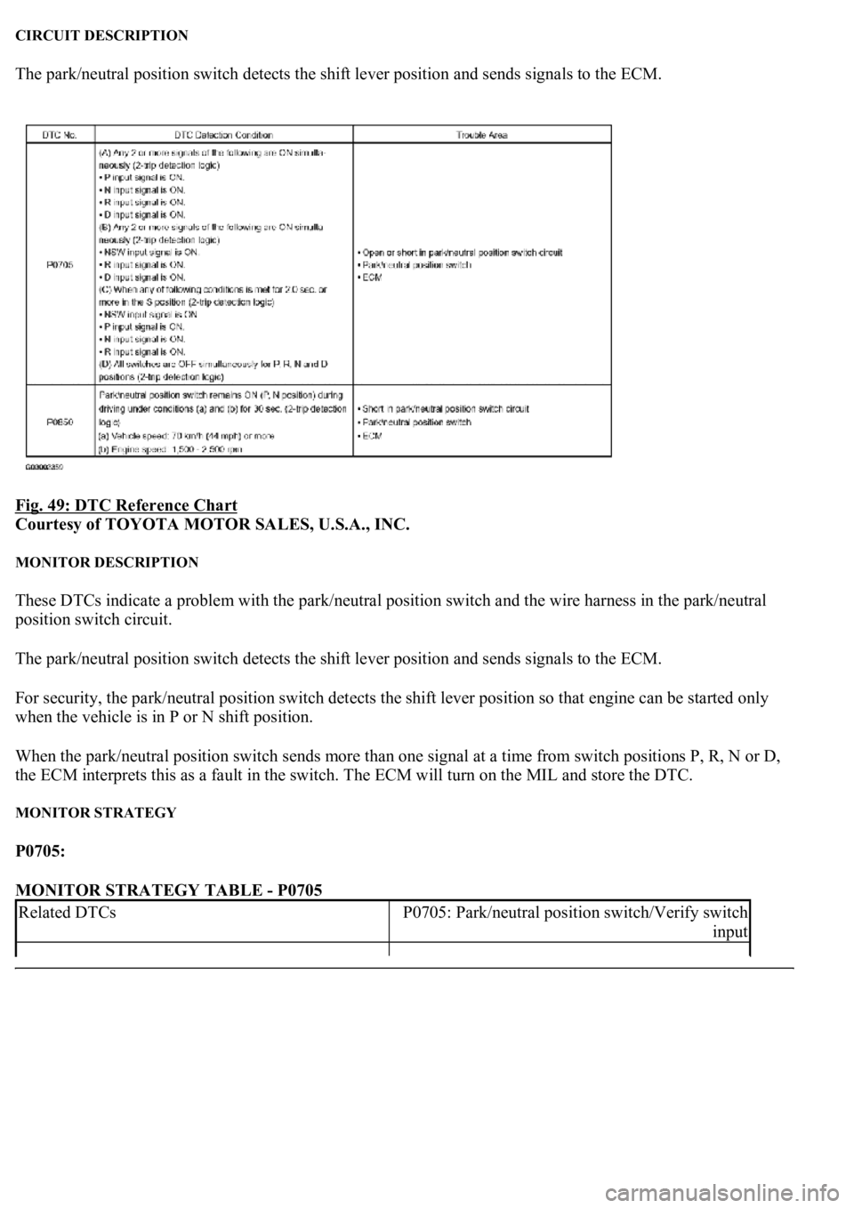
CIRCUIT DESCRIPTION
The park/neutral position switch detects the shift lever position and sends signals to the ECM.
Fig. 49: DTC Reference Chart
Courtesy of TOYOTA MOTOR SALES, U.S.A., INC.
MONITOR DESCRIPTION
These DTCs indicate a problem with the park/neutral position switch and the wire harness in the park/neutral
position switch circuit.
The park/neutral position switch detects the shift lever position and sends signals to the ECM.
For security, the park/neutral position switch detects the shift lever position so that engine can be started only
when the vehicle is in P or N shift position.
When the park/neutral position switch sends more than one signal at a time from switch positions P, R, N or D,
the ECM interprets this as a fault in the switch. The ECM will turn on the MIL and store the DTC.
MONITOR STRATEGY
P0705:
MONITOR STRATEGY TABLE - P0705
Related DTCsP0705: Park/neutral position switch/Verify switch
input
Page 2730 of 4500
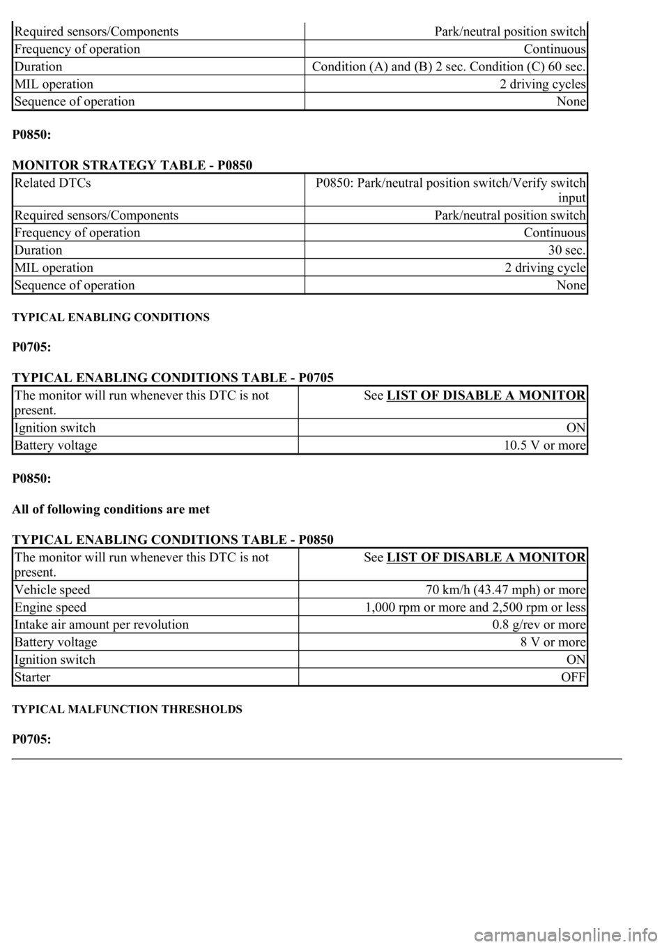
P0850:
MONITOR STRATEGY TABLE - P0850
TYPICAL ENABLING CONDITIONS
P0705:
TYPICAL ENABLING CONDITIONS TABLE - P0705
P0850:
All of following conditions are met
TYPICAL ENABLING CONDITIONS TABLE - P0850
TYPICAL MALFUNCTION THRESHOLDS
P0705:
Required sensors/ComponentsPark/neutral position switch
Frequency of operationContinuous
DurationCondition (A) and (B) 2 sec. Condition (C) 60 sec.
MIL operation2 driving cycles
Sequence of operationNone
Related DTCsP0850: Park/neutral position switch/Verify switch
input
Required sensors/ComponentsPark/neutral position switch
Frequency of operationContinuous
Duration30 sec.
MIL operation2 driving cycle
Sequence of operationNone
The monitor will run whenever this DTC is not
present.See LIST OF DISABLE A MONITOR
Ignition switchON
Battery voltage10.5 V or more
The monitor will run whenever this DTC is not
present.See LIST OF DISABLE A MONITOR
Vehicle speed70 km/h (43.47 mph) or more
Engine speed1,000 rpm or more and 2,500 rpm or less
Intake air amount per revolution0.8 g/rev or more
Battery voltage8 V or more
Ignition switchON
StarterOFF
Page 2731 of 4500
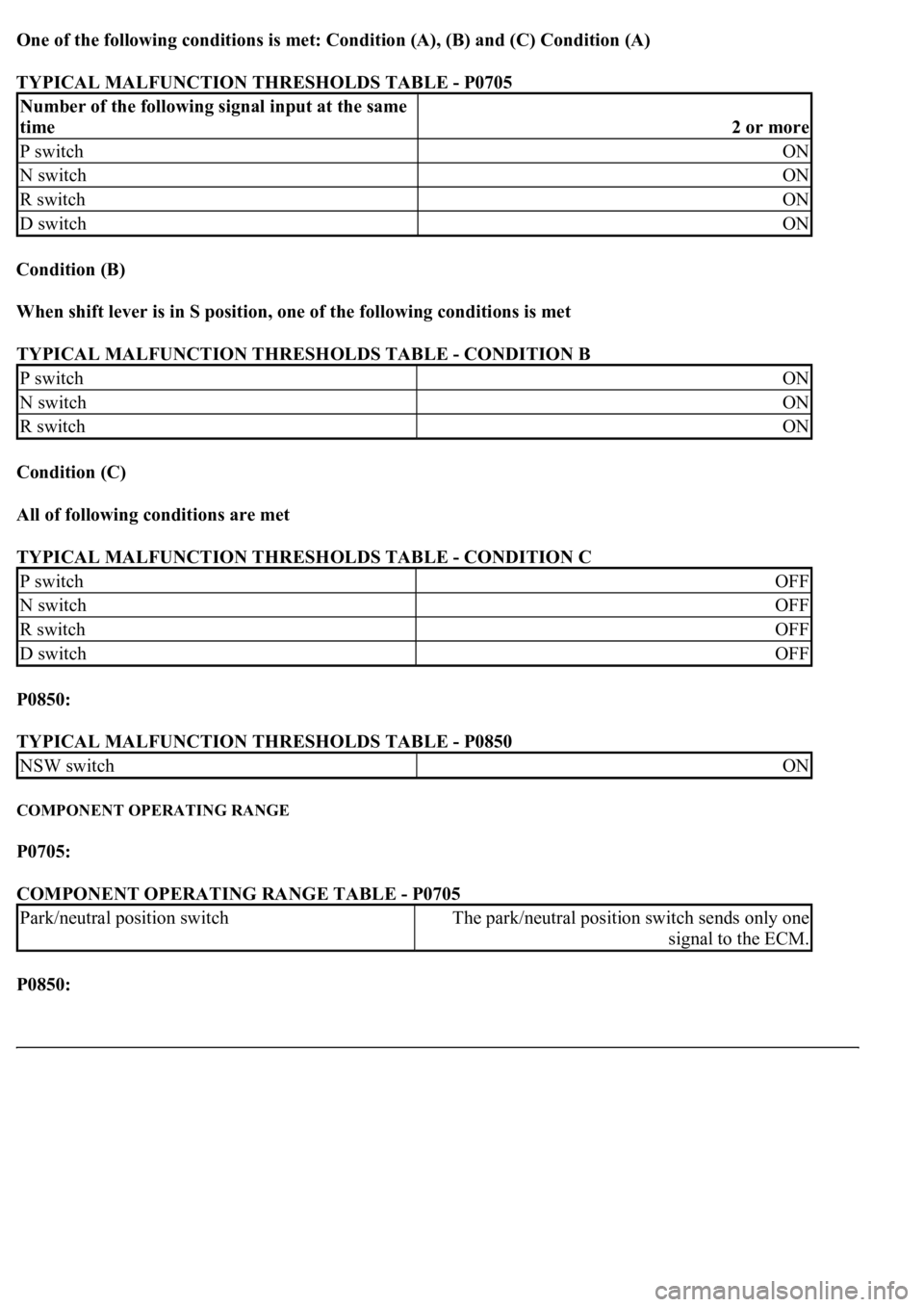
One of the following conditions is met: Condition (A), (B) and (C) Condition (A)
TYPICAL MALFUNCTION THRESHOLDS TABLE - P0705
Condition (B)
When shift lever is in S position, one of the following conditions is met
TYPICAL MALFUNCTION THRESHOLDS TABLE - CONDITION B
Condition (C)
All of following conditions are met
TYPICAL MALFUNCTION THRESHOLDS TABLE - CONDITION C
P0850:
TYPICAL MALFUNCTION THRESHOLDS TABLE - P0850
COMPONENT OPERATING RANGE
P0705:
COMPONENT OPERATING RANGE TABLE - P0705
P0850:
Number of the following signal input at the same
time
2 or more
P switchON
N switchON
R switchON
D switchON
P switchON
N switchON
R switchON
P switchOFF
N switchOFF
R switchOFF
D switchOFF
NSW switchON
Park/neutral position switchThe park/neutral position switch sends only one
signal to the ECM.
Page 2732 of 4500

COMPONENT OPERATING RANGE TABLE - P0850
WIRING DIAGRAM
Park/neutral position switchThe park/neutral position switch is OFF when
vehicle speed is 70 km/h or more and engine speed
is between 1,000 rpm or more and 2,500 rpm or
less.
Page 2734 of 4500

According to the DATA LIST displayed by the hand-held tester, you can read the value of the switch, sensor,
actuator and so on without parts removal. Reading the DATA LIST as the first step of troubleshooting is one
method to shorten labor time.
a. Turn the ignition switch off.
b. Connect the hand-held tester together with the CAN VIM (controller area network vehicle interface
module) to the DLC3.
c. Turn the ignition switch to the ON position.
d. Push the "ON" button of the OBD II scan tool or the hand-held tester.
e. Select the item "DIAGNOSIS/ENHANCED OBD II/DATA LIST".
f. According to the display on tester, read the "DATA LIST".
Fig. 51: Test Item Reference Chart
Courtesy of TOYOTA MOTOR SALES, U.S.A., INC.
1.INSPECT PARK/NEUTRAL POSITION SWITCH ASSY
a. Disconnect the park/neutral position switch connector.
b. Measure resistance according to the value(s) in the table below when the shift lever is moved to
each position.
Page 2735 of 4500
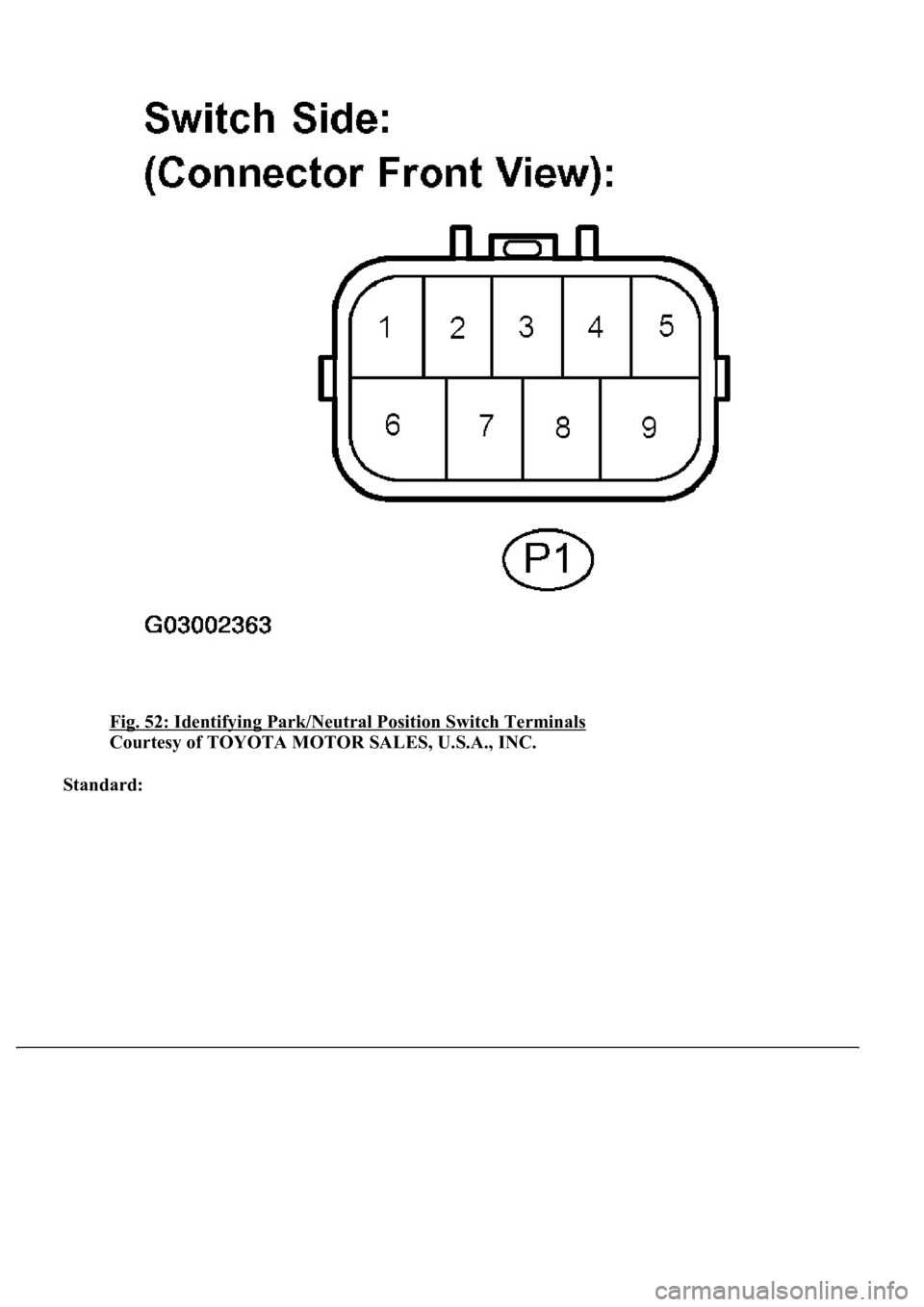
Fig. 52: Identifying Park/Neutral Position Switch Terminals
Courtesy of TOYOTA MOTOR SALES, U.S.A., INC.
Standard:
Page 2736 of 4500
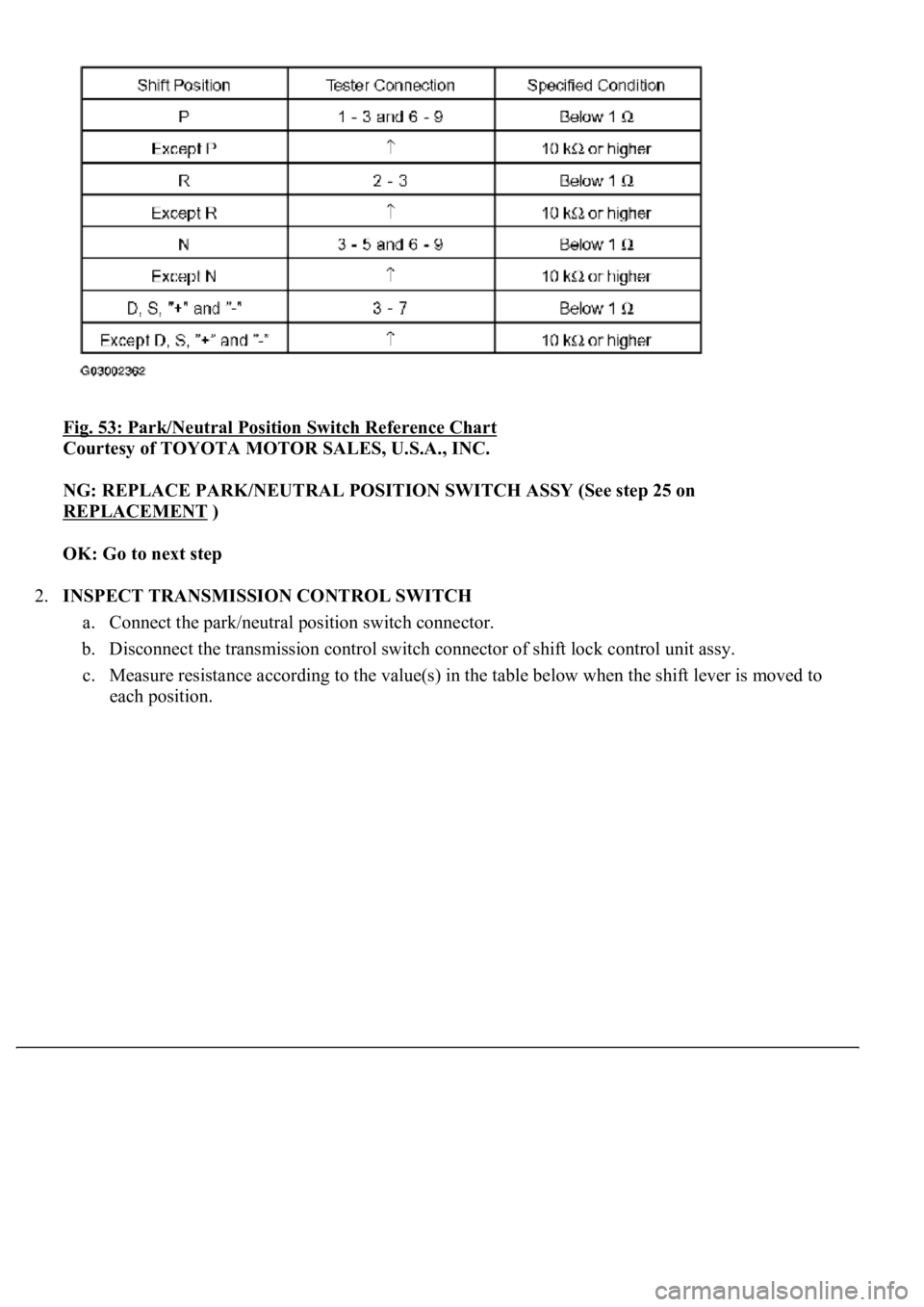
Fig. 53: Park/Neutral Position Switch Reference Chart
Courtesy of TOYOTA MOTOR SALES, U.S.A., INC.
NG: REPLACE PARK/NEUTRAL POSITION SWITCH ASSY (See step 25 on
REPLACEMENT
)
OK: Go to next step
2.INSPECT TRANSMISSION CONTROL SWITCH
a. Connect the park/neutral position switch connector.
b. Disconnect the transmission control switch connector of shift lock control unit assy.
c. Measure resistance according to the value(s) in the table below when the shift lever is moved to
each position.
Page 2738 of 4500
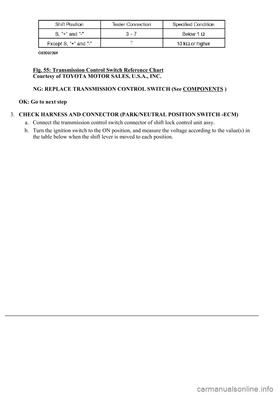
Fig. 55: Transmission Control Switch Reference Chart
Courtesy of TOYOTA MOTOR SALES, U.S.A., INC.
NG: REPLACE TRANSMISSION CONTROL SWITCH (See COMPONENTS
)
OK: Go to next step
3.CHECK HARNESS AND CONNECTOR (PARK/NEUTRAL POSITION SWITCH -ECM)
a. Connect the transmission control switch connector of shift lock control unit assy.
b. Turn the ignition switch to the ON position, and measure the voltage according to the value(s) in
the table below when the shift lever is moved to each position.
Page 2766 of 4500
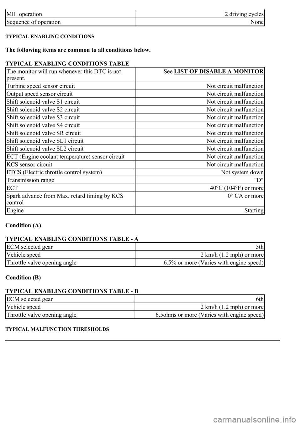
TYPICAL ENABLING CONDITIONS
The following items are common to all conditions below.
TYPICAL ENABLING CONDITIONS TABLE
Condition (A)
TYPICAL ENABLING CONDITIONS TABLE - A
Condition (B)
TYPICAL ENABLING CONDITIONS TABLE - B
TYPICAL MALFUNCTION THRESHOLDS
MIL operation2 driving cycles
Sequence of operationNone
The monitor will run whenever this DTC is not
present.See LIST OF DISABLE A MONITOR
Turbine speed sensor circuitNot circuit malfunction
Output speed sensor circuitNot circuit malfunction
Shift solenoid valve S1 circuitNot circuit malfunction
Shift solenoid valve S2 circuitNot circuit malfunction
Shift solenoid valve S3 circuitNot circuit malfunction
Shift solenoid valve S4 circuitNot circuit malfunction
Shift solenoid valve SR circuitNot circuit malfunction
Shift solenoid valve SL1 circuitNot circuit malfunction
Shift solenoid valve SL2 circuitNot circuit malfunction
ECT (Engine coolant temperature) sensor circuitNot circuit malfunction
KCS sensor circuitNot circuit malfunction
ETCS (Electric throttle control system)Not system down
Transmission range"D"
ECT40°C (104°F) or more
Spark advance from Max. retard timing by KCS
control0° CA or more
EngineStarting
ECM selected gear5th
Vehicle speed2 km/h (1.2 mph) or more
Throttle valve opening angle6.5% or more (Varies with engine speed)
ECM selected gear6th
Vehicle speed2 km/h (1.2 mph) or more
Throttle valve opening angle6.5ohms or more (Varies with engine speed)
Page 2778 of 4500
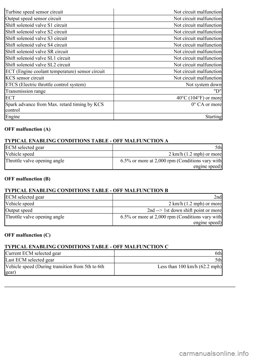
OFF malfunction (A)
TYPICAL ENABLING CONDITIONS TABLE - OFF MALFUNCTION A
OFF malfunction (B)
TYPICAL ENABLING CONDITIONS TABLE - OFF MALFUNCTION B
OFF malfunction (C)
TYPICAL ENABLING CONDITIONS TABLE - OFF MALFUNCTION C
Turbine speed sensor circuitNot circuit malfunction
Output speed sensor circuitNot circuit malfunction
Shift solenoid valve S1 circuitNot circuit malfunction
Shift solenoid valve S2 circuitNot circuit malfunction
Shift solenoid valve S3 circuitNot circuit malfunction
Shift solenoid valve S4 circuitNot circuit malfunction
Shift solenoid valve SR circuitNot circuit malfunction
Shift solenoid valve SL1 circuitNot circuit malfunction
Shift solenoid valve SL2 circuitNot circuit malfunction
ECT (Engine coolant temperature) sensor circuitNot circuit malfunction
KCS sensor circuitNot circuit malfunction
ETCS (Electric throttle control system)Not system down
Transmission range"D"
ECT40°C (104°F) or more
Spark advance from Max. retard timing by KCS
control0° CA or more
EngineStarting
ECM selected gear5th
Vehicle speed2 km/h (1.2 mph) or more
Throttle valve opening angle6.5% or more at 2,000 rpm (Conditions vary with
engine speed)
ECM selected gear2nd
Vehicle speed2 km/h (1.2 mph) or more
Output speed2nd --> 1st down shift point or more
Throttle valve opening angle6.5% or more at 2,000 rpm (Conditions vary with
engine speed)
Current ECM selected gear6th
Last ECM selected gear5th
Vehicle speed (During transition from 5th to 6th
gear)Less than 100 km/h (62.2 mph)