LEXUS LS430 2003 Factory User Guide
LS430 2003
LEXUS
LEXUS
https://www.carmanualsonline.info/img/36/57050/w960_57050-0.png
LEXUS LS430 2003 Factory User Guide
Page 356 of 4500
Courtesy of TOYOTA MOTOR SALES, U.S.A., INC.
NG: REPAIR OR REPLACE HARNESS OR CONNECTOR
OK: REPLACE AIR CONDITIONING AMPLIFIER (SEE REPLACEMENT
)
CIRCUIT DESCRIPTION
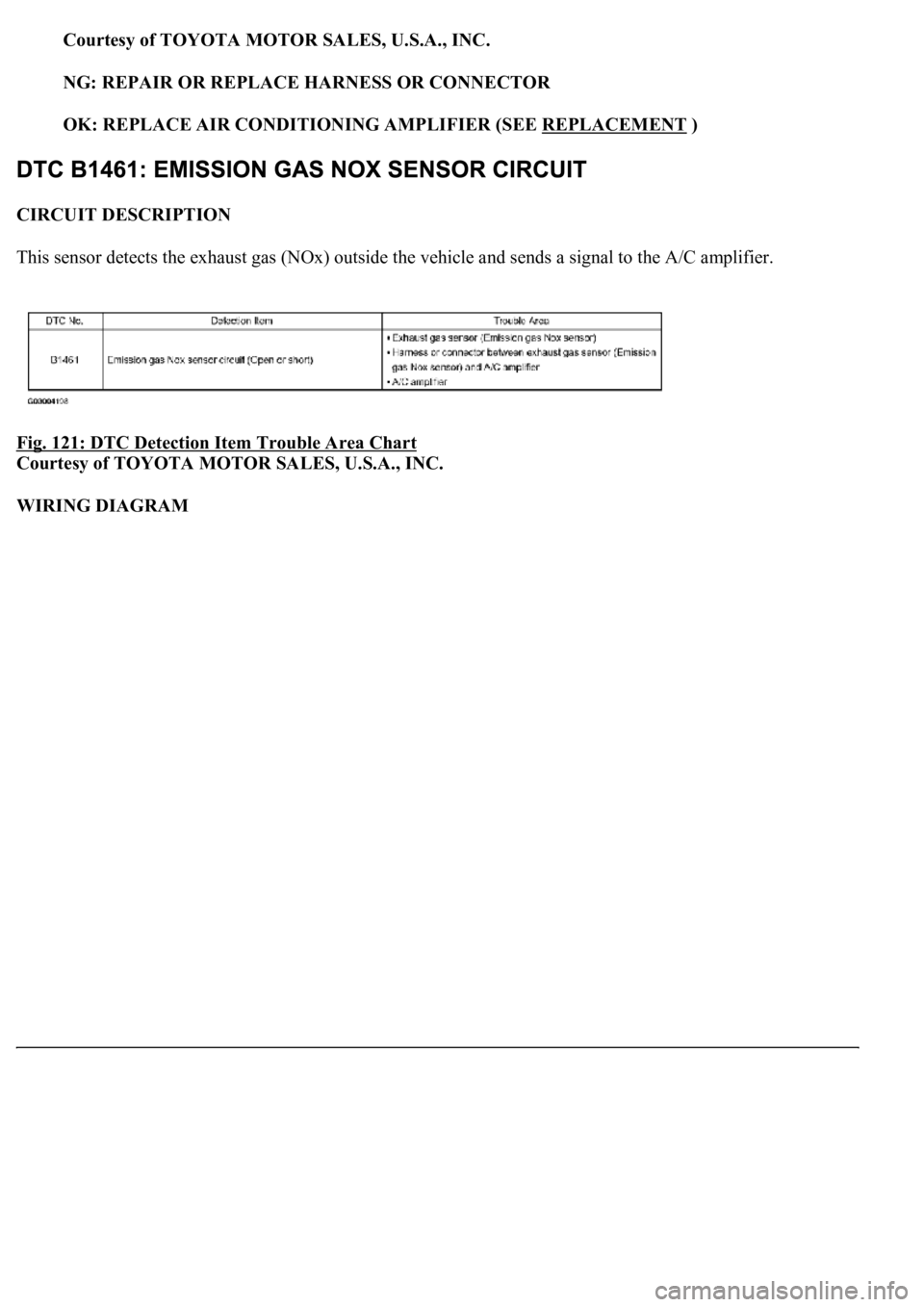
This sensor detects the exhaust gas (NOx) outside the vehicle and sends a signal to the A/C amplifier.
Fig. 121: DTC Detection Item Trouble Area Chart
Courtesy of TOYOTA MOTOR SALES, U.S.A., INC.
WIRING DIAGRAM
Page 363 of 4500
NG: REPAIR OR REPLACE HARNESS OR CONNECTOR
OK: REPLACE AIR CONDITIONING AMPLIFIER (SEE REPLACEMENT )
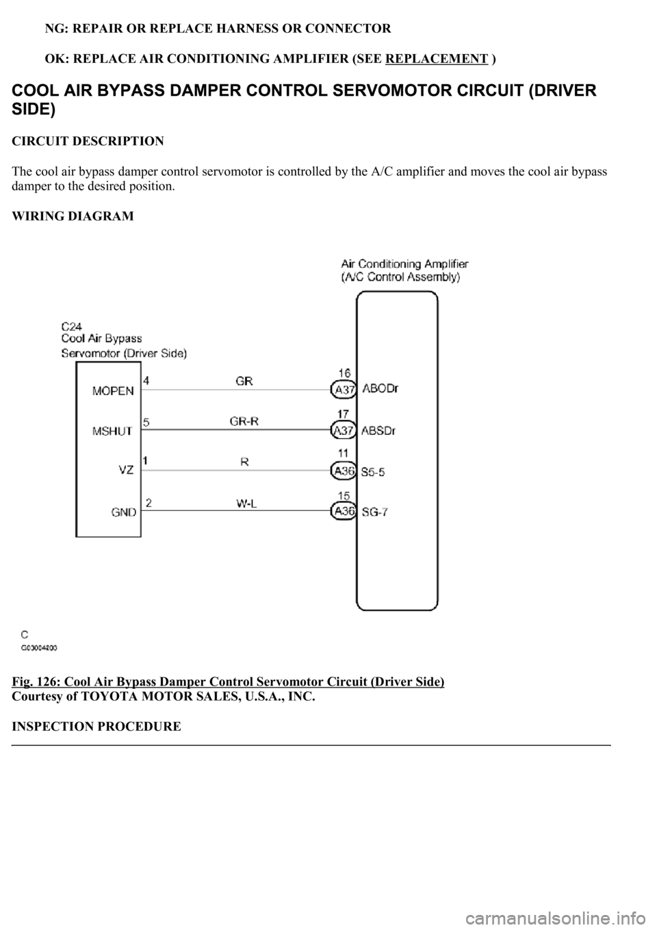
CIRCUIT DESCRIPTION
The cool air bypass damper control servomotor is controlled by the A/C amplifier and moves the cool air bypass
damper to the desired position.
WIRING DIAGRAM
Fig. 126: Cool Air Bypass Damper Control Servomotor Circuit (Driver Side)
Courtesy of TOYOTA MOTOR SALES, U.S.A., INC.
INSPECTION PROCEDURE
Page 368 of 4500
Amplifier)
Courtesy of TOYOTA MOTOR SALES, U.S.A., INC.
NG: REPAIR OR REPLACE HARNESS OR CONNECTOR
OK: REPLACE AIR CONDITIONING AMPLIFIER (SEE REPLACEMENT
)
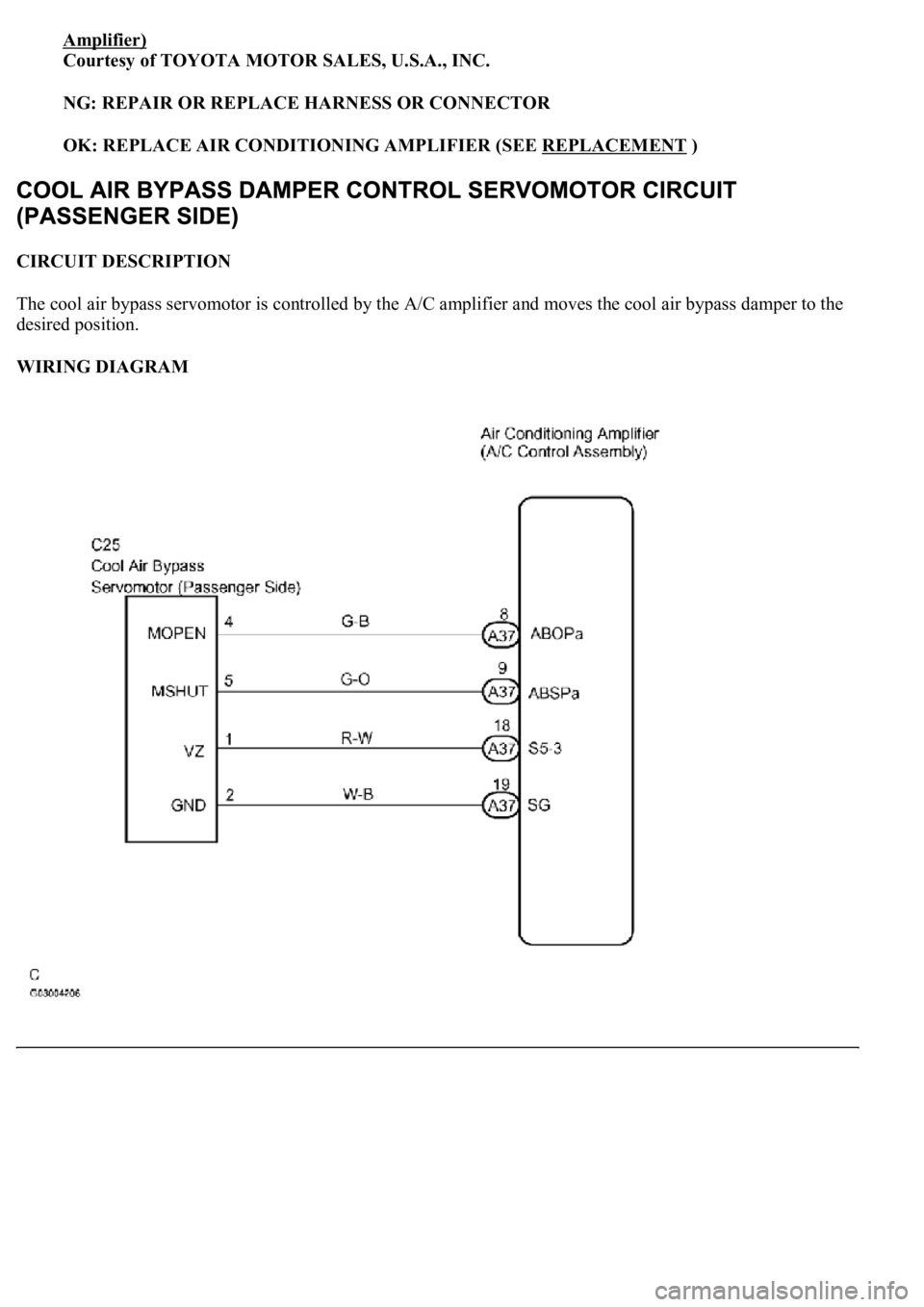
CIRCUIT DESCRIPTION
The cool air bypass servomotor is controlled by the A/C amplifier and moves the cool air bypass damper to the
desired position.
WIRING DIAGRAM
Page 373 of 4500
Amplifier)
Courtesy of TOYOTA MOTOR SALES, U.S.A., INC.
NG: REPAIR OR REPLACE HARNESS OR CONNECTOR
OK: REPLACE AIR CONDITIONING AMPLIFIER (SEE REPLACEMENT
)
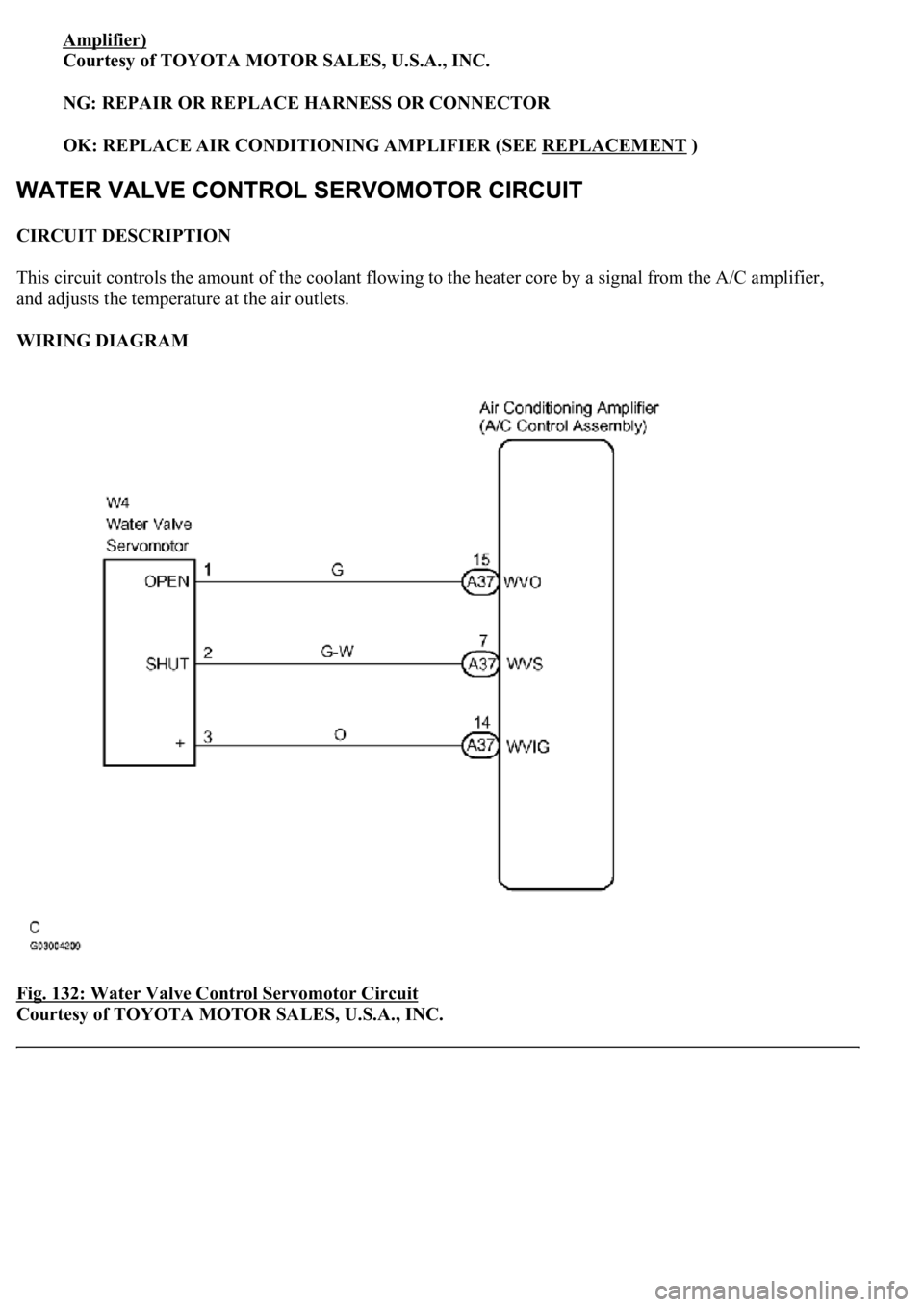
CIRCUIT DESCRIPTION
This circuit controls the amount of the coolant flowing to the heater core by a signal from the A/C amplifier,
and adjusts the temperature at the air outlets.
WIRING DIAGRAM
Fig. 132: Water Valve Control Servomotor Circuit
Courtesy of TOYOTA MOTOR SALES, U.S.A., INC.
Page 378 of 4500
Amplifier)
Courtesy of TOYOTA MOTOR SALES, U.S.A., INC.
NG: REPAIR OR REPLACE HARNESS OR CONNECTOR
OK: REPLACE AIR CONDITIONING AMPLIFIER (SEE REPLACEMENT
)
CIRCUIT DESCRIPTION
This circuit turns the servomotor and changes each damper position by receiving the signals from the A/C
amplifier assy. When the AUTO switch is on, the A/C amplifier changes the mode between "FACE", "BI-
LEVEL" and "FOOT" following the temperature setting.
WIRING DIAGRAM
Page 388 of 4500
Courtesy of TOYOTA MOTOR SALES, U.S.A., INC.
OK: REPLACE AIR CONDITIONING AMPLIFIER (SEE REPLACEMENT
)
CIRCUIT DESCRIPTION
This servomotor is controlled by the A/C amplifier. Air flow temperature changes when moving the air mix
damper to the target point. The target point can be detected with the air mix damper position sensor.
WIRING DIAGRAM
Page 399 of 4500
Courtesy of TOYOTA MOTOR SALES, U.S.A., INC.
NG: REPAIR OR REPLACE HARNESS OR / CONNECTOR
OK: REPLACE AIR CONDITIONING AMPLIFIER (SEE REPLACEMENT
)
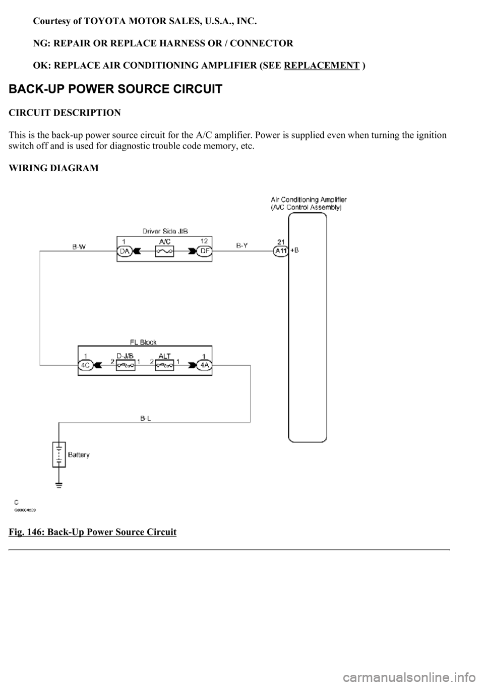
CIRCUIT DESCRIPTION
This is the back-up power source circuit for the A/C amplifier. Power is supplied even when turning the ignition
switch off and is used for diagnostic trouble code memory, etc.
WIRING DIAGRAM
Fig. 146: Back
-Up Power Source Circuit
Page 402 of 4500
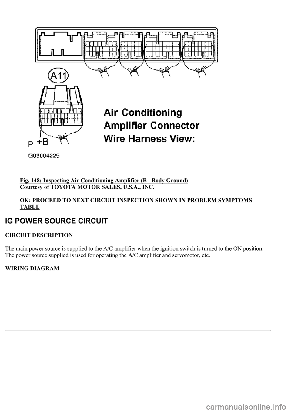
Fig. 148: Inspecting Air Conditioning Amplifier (B - Body Ground)
Courtesy of TOYOTA MOTOR SALES, U.S.A., INC.
OK: PROCEED TO NEXT CIRCUIT INSPECTION SHOWN IN PROBLEM SYMPTOMS
TABLE
CIRCUIT DESCRIPTION
The main power source is supplied to the A/C amplifier when the ignition switch is turned to the ON position.
The power source supplied is used for operating the A/C amplifier and servomotor, etc.
WIRING DIAGRAM
Page 407 of 4500
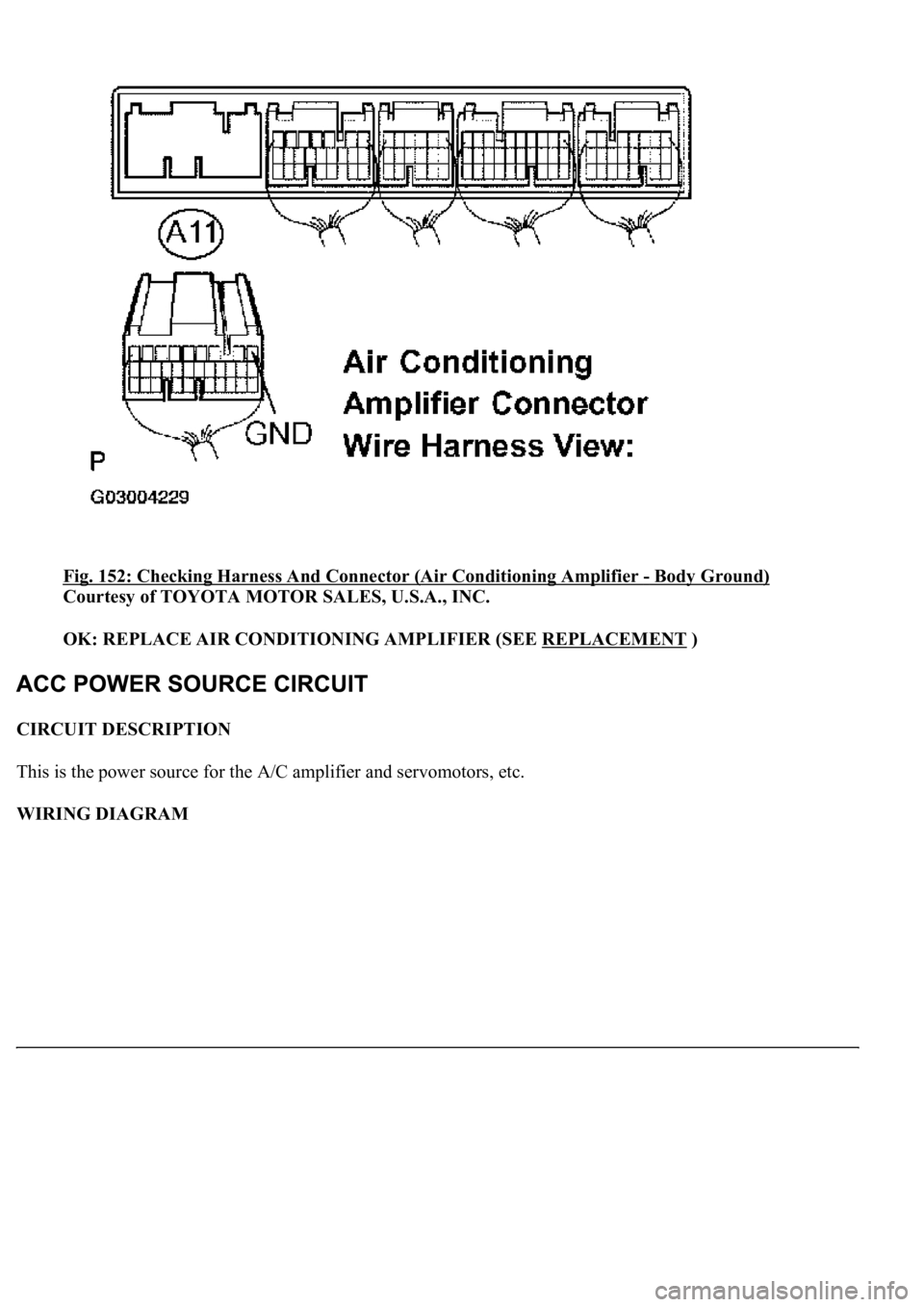
Fig. 152: Checking Harness And Connector (Air Conditioning Amplifier - Body Ground)
Courtesy of TOYOTA MOTOR SALES, U.S.A., INC.
OK: REPLACE AIR CONDITIONING AMPLIFIER (SEE REPLACEMENT
)
CIRCUIT DESCRIPTION
This is the power source for the A/C amplifier and servomotors, etc.
WIRING DIAGRAM
Page 421 of 4500
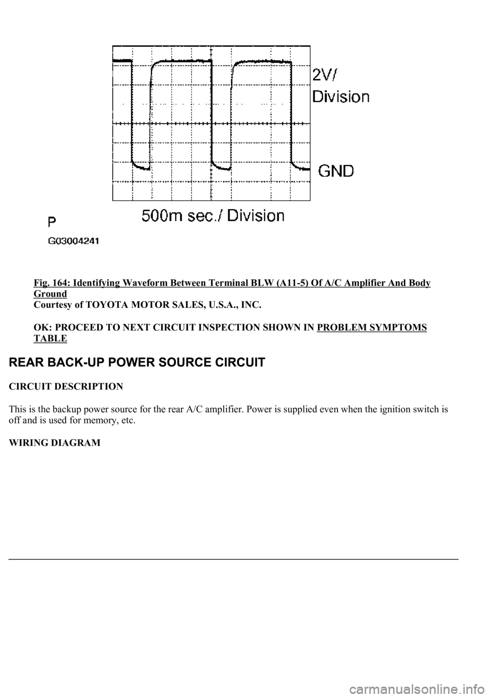
Fig. 164: Identifying Waveform Between Terminal BLW (A11-5) Of A/C Amplifier And Body
Ground
Courtesy of TOYOTA MOTOR SALES, U.S.A., INC.
OK: PROCEED TO NEXT CIRCUIT INSPECTION SHOWN IN PROBLEM SYMPTOMS
TABLE
CIRCUIT DESCRIPTION
This is the backup power source for the rear A/C amplifier. Power is supplied even when the ignition switch is
off and is used for memory, etc.
WIRING DIAGRAM
