ECU LEXUS LS430 2003 Factory User Guide
[x] Cancel search | Manufacturer: LEXUS, Model Year: 2003, Model line: LS430, Model: LEXUS LS430 2003Pages: 4500, PDF Size: 87.45 MB
Page 19 of 4500
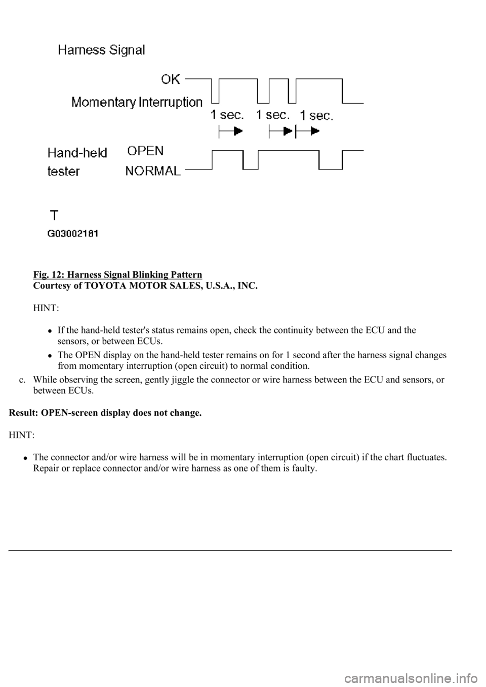
Fig. 12: Harness Signal Blinking Pattern
Courtesy of TOYOTA MOTOR SALES, U.S.A., INC.
HINT:
If the hand-held tester's status remains open, check the continuity between the ECU and the
sensors, or between ECUs.
The OPEN display on the hand-held tester remains on for 1 second after the harness signal changes
from momentary interruption (open circuit) to normal condition.
c. While observing the screen, gently jiggle the connector or wire harness between the ECU and sensors, or
between ECUs.
Result: OPEN-screen display does not change.
HINT:
The connector and/or wire harness will be in momentary interruption (open circuit) if the chart fluctuates.
Repair or replace connector and/or wire harness as one of them is fault
y.
Page 25 of 4500
HINT:
<003a004b0048005100030057004b00480003005300440055004e004c0051004a0003004500550044004e00480003004c00560003004400530053004f004c0048004700030052005500030057004b00480003004f004800590048004f000300520049000300
57004b00480003004500550044004e004800030049004f0058[id is low, the BRAKE warning light
comes on.
b. When the ignition switch is turned to the ON position, check that the ABS warning light, TRAC
OFF indicator light, BRAKE warning light and SLIP indicator light come on for approximately 3
seconds.
HINT:
If the ECU was any stored DTCs, the ABS warning light, "VSC" is displayed on the multi-
information display and TRAC OFF indicator light come on.
If the indicator does not come on, inspect it the bulb is blown out, and also the wire harness
between the skid control ECU and the combination meter.
Page 39 of 4500
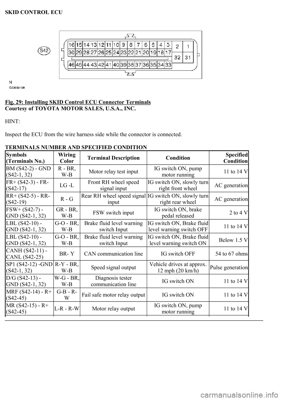
SKID CONTROL ECU
Fig. 29: Installing SKID Control ECU Connector Terminals
Courtesy of TOYOTA MOTOR SALES, U.S.A., INC.
HINT:
Inspect the ECU from the wire harness side while the connector is connected.
TERMINALS NUMBER AND SPECIFIED CONDITION
Symbols
(Terminals No.)Wiring
ColorTerminal DescriptionConditionSpecified
Condition
BM (S42-2) - GND
(S42-1, 32)R - BR,
W-BMotor relay test inputIG switch ON, pump
motor running11 to 14 V
FR+ (S42-3) - FR-
(S42-17)LG -LFront RH wheel speed
signal inputIG switch ON, slowly turn
right front wheelAC generation
RR+ (S42-5) - RR-
(S42-19)R - GRear RH wheel speed signal
inputIG switch ON, slowly turn
right rear wheelAC generation
FSW+ (S42-7) -
GND (S42-1, 32)GR - BR,
W-BFSW switch inputIG switch ON, brake
pedal released2 to 4 V
LBL (S42-10) -
GND (S42-1, 32)G-O - BR,
W-BBrake fluid level warning
switch InputIG switch ON, Brake fluid
level warning switch OFF11 to 14 V
LBL (S42-10) -
GND (S42-1, 32)G-O - BR,
W-BBrake fluid level warning
switch InputIG switch ON, Brake fluid
level warning switch ONBelow 1.5 V
CANH (S42-11) -
CANL (S42-25)BR- YCAN communication lineIG switch OFF54 to 67 ohms
SP1 (S42-12) -GND
(S42-1, 32)R-Y - BR,
W-BSpeed signal outputVehicle drives at approx.
12 mph (20 km/h)Pulse generation
D/G (S42-13) -
GND (S42-1, 32)W-G - BR,
W-BDiagnosis tester
communication lineIG switch ON11 to 14 V
MRF (S42-14) - R+
(S42-45)G-B - R-
WFail safe motor relay outputIG switch ON11 to 14 V
MR (S42-15) - R+
(S42-45)L-R - R-WMotor relay outputIG switch ON, pump
motor running11 to 14 V
Page 41 of 4500
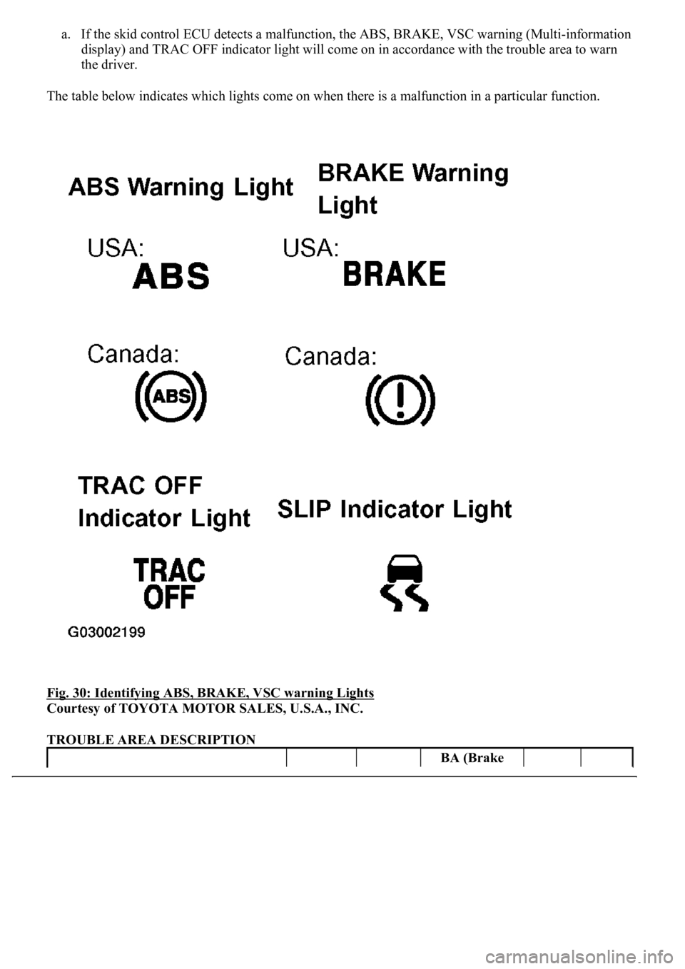
a. If the skid control ECU detects a malfunction, the ABS, BRAKE, VSC warning (Multi-information
display) and TRAC OFF indicator light will come on in accordance with the trouble area to warn
the driver.
The table below indicates which lights come on when there is a malfunction in a particular function.
Fig. 30: Identifying ABS, BRAKE, VSC warning Lights
Courtesy of TOYOTA MOTOR SALES, U.S.A., INC.
TROUBLE AREA DESCRIPTION
BA (Brake
Page 48 of 4500
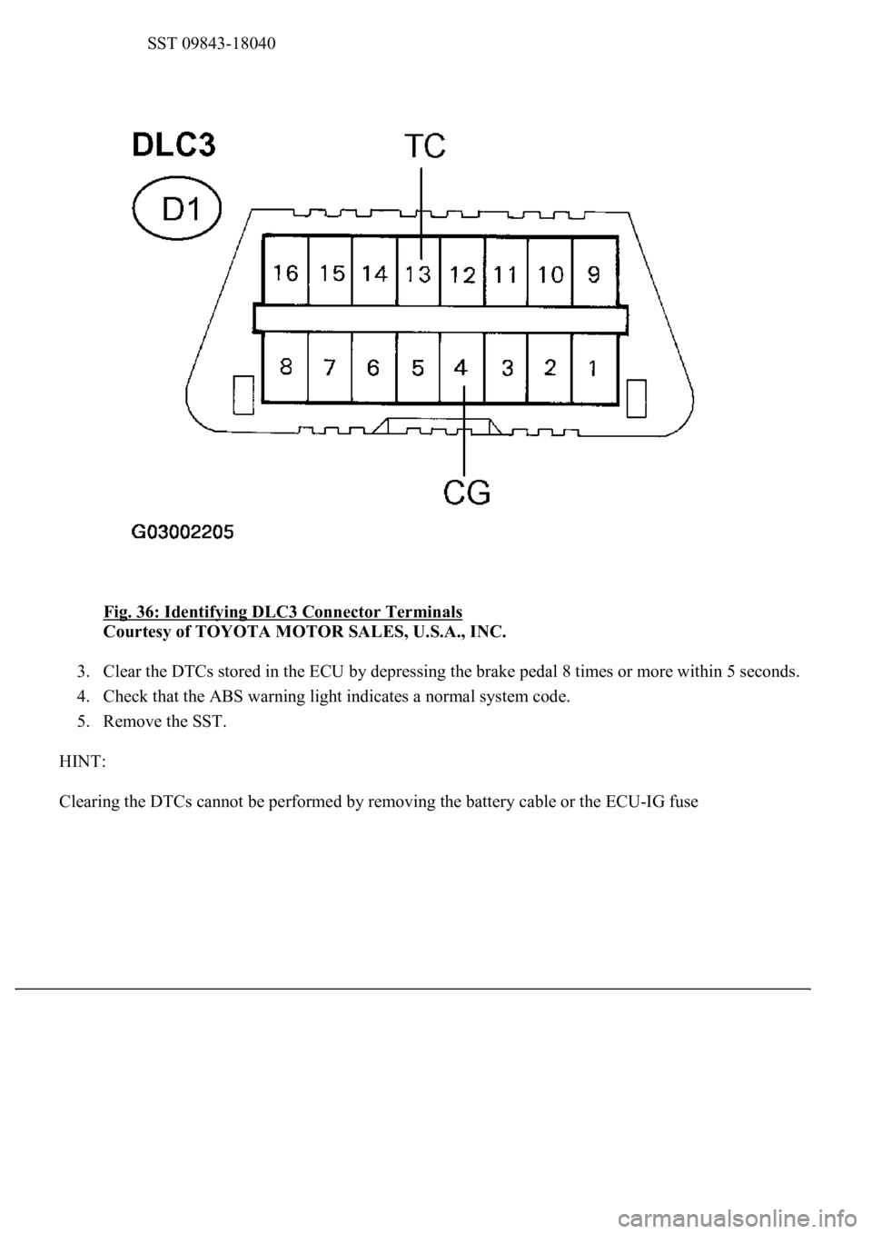
SST 09843-18040
Fig. 36: Identifying DLC3 Connector Terminals
Courtesy of TOYOTA MOTOR SALES, U.S.A., INC.
3. Clear the DTCs stored in the ECU by depressing the brake pedal 8 times or more within 5 seconds.
4. Check that the ABS warning light indicates a normal system code.
5. Remove the SST.
HINT:
Clearin
g the DTCs cannot be performed by removing the battery cable or the ECU-IG fuse
Page 50 of 4500
Whenever a DTC is detected or the ABS operates, the skid control ECU stores the current vehicle
(sensor) state as freeze frame data.
The skid control ECU stores the number of times (maximum: 31) the ignition switch has been turned
from off to the ON position since the last time ABS was activated. However, if the vehicle was stopped or
at low speed (4.3 mph (7 km/h) or less), or if a DTC is detected, the skid control ECU will not count the
number after that.
Freeze frame data at the time the ABS operates:
The skid control ECU stores and updates data whenever the ABS system operates.
When the ECU stores data at the time a DTC is detected, the data stored when the ABS operated is
erased.
Freeze frame data at the time a DTC is detected:
When the skid control ECU stores data at the time a DTC is detected, no updates will be performed until
the data is cleared.
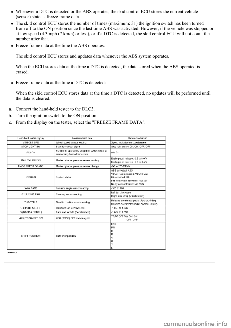
a. Connect the hand-held tester to the DLC3.
b. Turn the ignition switch to the ON position.
c. From the display on the tester, select the "FREEZE FRAME DATA".
Page 60 of 4500
CIRCUIT DESCRIPTION
The speed sensor detects wheel speed and sends the appropriate signals to the ECU. These signals are used to
control the ABS control system. The front and rear rotors have 48 serrations respectively.
When the rotors rotate, the magnetic field emitted by the permanent magnet in the speed sensor generates an
AC voltage. Since the frequency of this AC voltage changes in direct proportion to the speed of the rotor, the
frequenc
y is used by the ECU to detect the speed of each wheel.
Page 64 of 4500
OK: Go to next step
3.INSPECT SPEED SENSOR AND SENSOR ROTOR SERRATIONS
INSPECTION USING OSCILLOSCOPE
a. Connect the oscilloscope to terminal FR+ - FR- or FL+ - FL- of the skid control ECU.
b. Drive the vehicle at approximately 19 mph (30 km/h), and check the signal waveform.
OK: Go to next step
A waveform as shown in a figure should be output.
HINT:
As the vehicle speed (wheel revolution speed) increases, a cycle of the waveform narrows and the
fluctuation in the output voltage becomes greater.
When noise is identified in the waveform on the oscilloscope, error signals are generated due to the
speed sensor rotor's scratches, looseness or foreign matter attached to it.
NG: Go to step 7
Page 67 of 4500
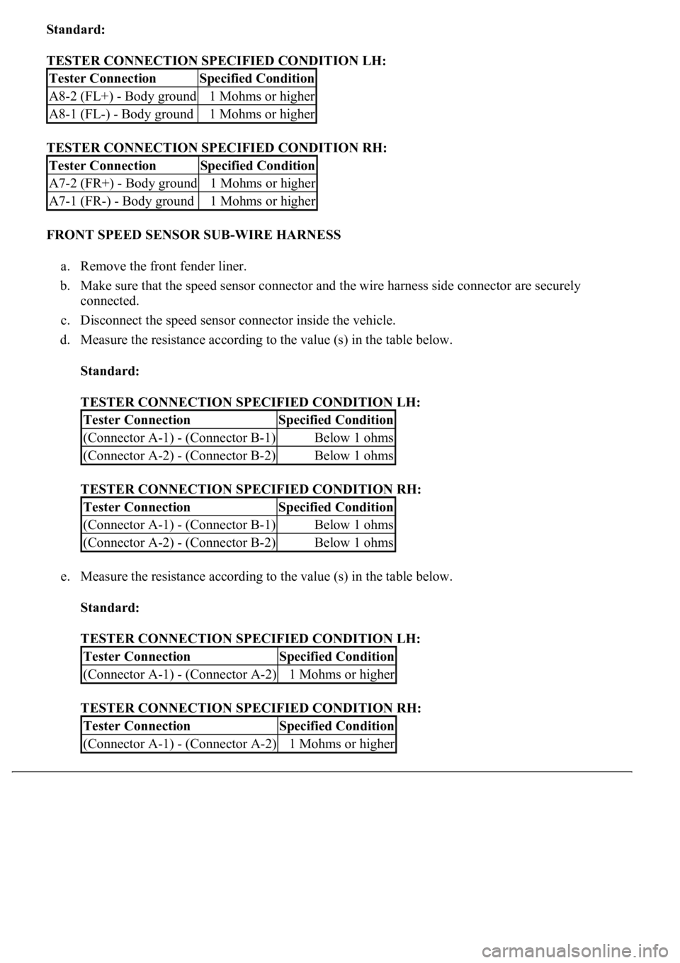
Standard:
TESTER CONNECTION SPECIFIED CONDITION LH:
TESTER CONNECTION SPECIFIED CONDITION RH:
FRONT SPEED SENSOR SUB-WIRE HARNESS
a. Remove the front fender liner.
b. Make sure that the speed sensor connector and the wire harness side connector are securely
connected.
c. Disconnect the speed sensor connector inside the vehicle.
d. Measure the resistance according to the value (s) in the table below.
Standard:
TESTER CONNECTION SPECIFIED CONDITION LH:
TESTER CONNECTION SPECIFIED CONDITION RH:
e. Measure the resistance according to the value (s) in the table below.
Standard:
TESTER CONNECTION SPECIFIED CONDITION LH:
TESTER CONNECTION SPECIFIED CONDITION RH:
Tester ConnectionSpecified Condition
A8-2 (FL+) - Body ground1 Mohms or higher
A8-1 (FL-) - Body ground1 Mohms or higher
Tester ConnectionSpecified Condition
A7-2 (FR+) - Body ground1 Mohms or higher
A7-1 (FR-) - Body ground1 Mohms or higher
Tester ConnectionSpecified Condition
(Connector A-1) - (Connector B-1)Below 1 ohms
(Connector A-2) - (Connector B-2)Below 1 ohms
Tester ConnectionSpecified Condition
(Connector A-1) - (Connector B-1)Below 1 ohms
(Connector A-2) - (Connector B-2)Below 1 ohms
Tester ConnectionSpecified Condition
(Connector A-1) - (Connector A-2)1 Mohms or higher
Tester ConnectionSpecified Condition
(Connector A-1) - (Connector A-2)1 Mohms or higher
Page 70 of 4500
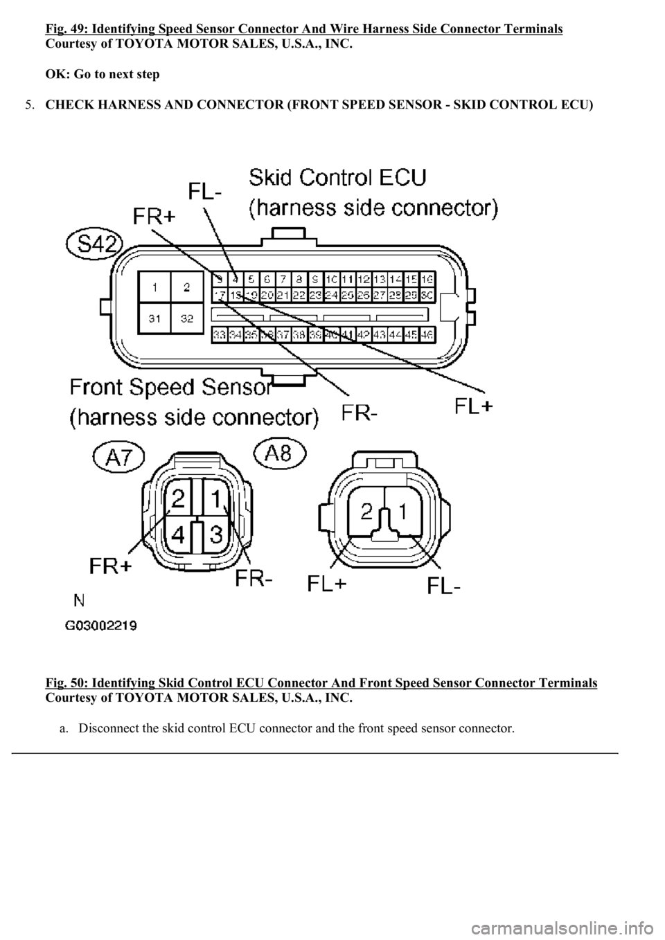
Fig. 49: Identifying Speed Sensor Connector And Wire Harness Side Connector Terminals
Courtesy of TOYOTA MOTOR SALES, U.S.A., INC.
OK: Go to next step
5.CHECK HARNESS AND CONNECTOR (FRONT SPEED SENSOR - SKID CONTROL ECU)
Fig. 50: Identifying Skid Control ECU Connector And Front Speed Sensor Connector Terminals
Courtesy of TOYOTA MOTOR SALES, U.S.A., INC.
a. Disconnect the skid control ECU connector and the front speed sensor connector.