LEXUS LS430 2003 Factory User Guide
LS430 2003
LEXUS
LEXUS
https://www.carmanualsonline.info/img/36/57050/w960_57050-0.png
LEXUS LS430 2003 Factory User Guide
Page 126 of 4500
TESTER CONNECTION SPECIFIED CONDITION
NG: REPAIR OR REPLACE HARNESS OR CONNECTOR (GND TERMINAL - BODY
GROUND)
Fig. 92: Identifying Skid Control ECU Connector Terminals
Courtesy of TOYOTA MOTOR SALES, U.S.A., INC.
OK: CHECK AND REPAIR HARNESS AND CONNECTOR (IG1 TERMINAL - BATTERY)
CIRCUIT DESCRIPTION
Master c
ylinder pressure sensor is connected to the skid control ECU in the actuator.
Tester ConnectionSpecified Condition
S42-32 (GND) - Body groundBelow 1ohms
Page 129 of 4500
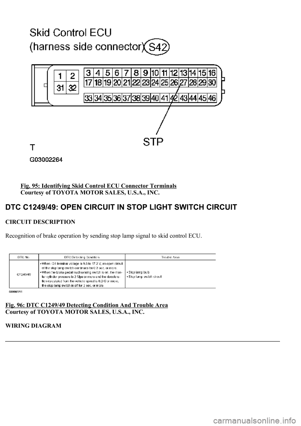
Fig. 95: Identifying Skid Control ECU Connector Terminals
Courtesy of TOYOTA MOTOR SALES, U.S.A., INC.
CIRCUIT DESCRIPTION
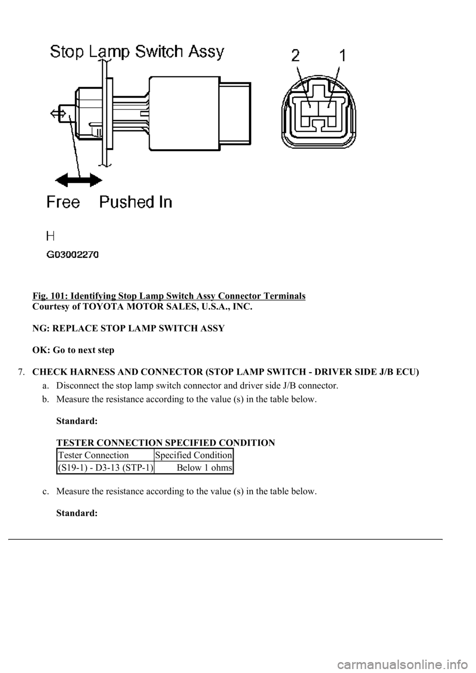
Recognition of brake operation by sending stop lamp signal to skid control ECU.
Fig. 96: DTC C1249/49 Detecting Condition And Trouble Area
Courtesy of TOYOTA MOTOR SALES, U.S.A., INC.
WIRING DIAGRAM
Page 136 of 4500
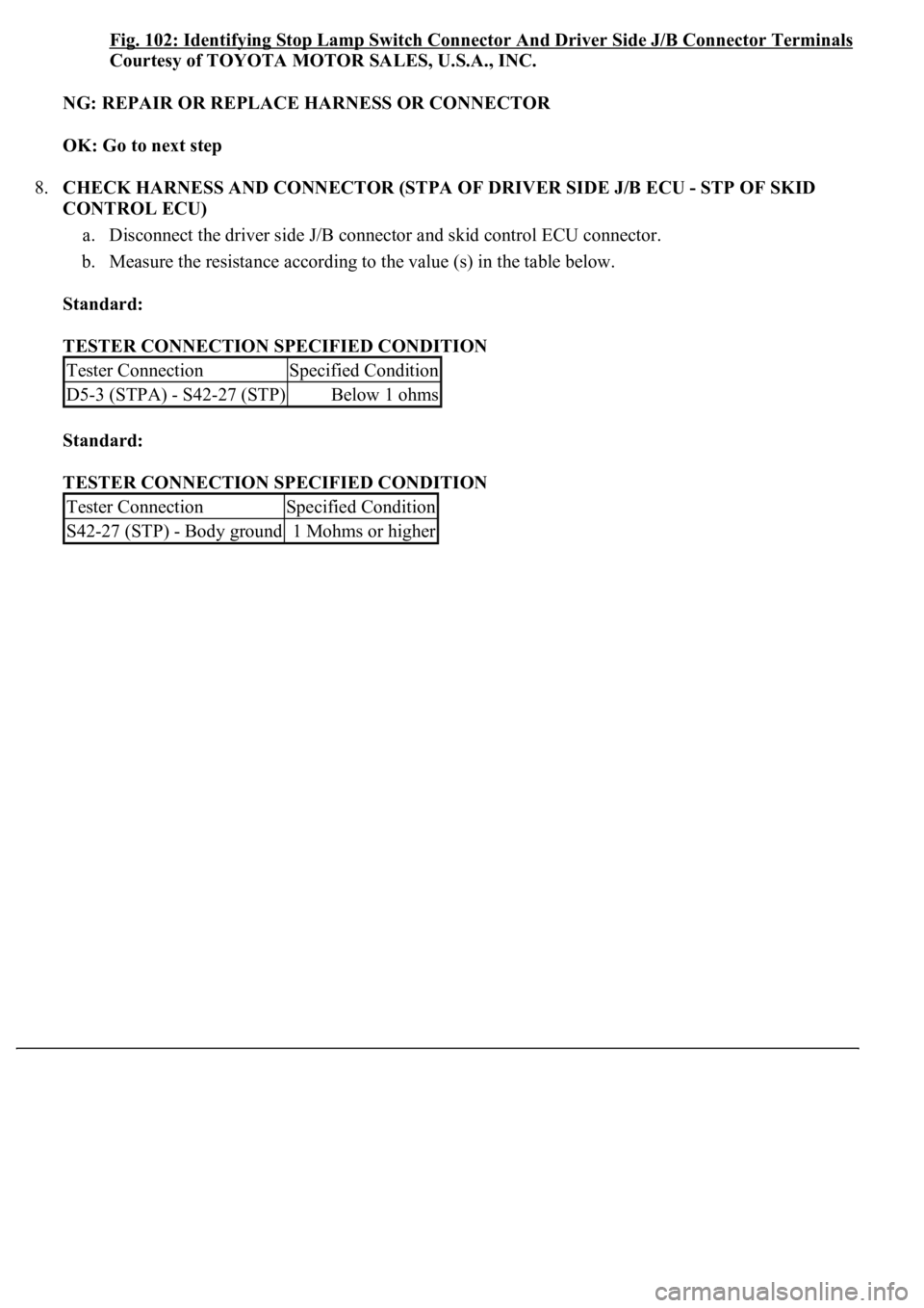
Fig. 101: Identifying Stop Lamp Switch Assy Connector Terminals
Courtesy of TOYOTA MOTOR SALES, U.S.A., INC.
NG: REPLACE STOP LAMP SWITCH ASSY
OK: Go to next step
7.CHECK HARNESS AND CONNECTOR (STOP LAMP SWITCH - DRIVER SIDE J/B ECU)
a. Disconnect the stop lamp switch connector and driver side J/B connector.
b. Measure the resistance according to the value (s) in the table below.
Standard:
TESTER CONNECTION SPECIFIED CONDITION
c. Measure the resistance according to the value (s) in the table below.
Standard:
Tester ConnectionSpecified Condition
(S19-1) - D3-13 (STP-1)Below 1 ohms
Page 138 of 4500
Fig. 102: Identifying Stop Lamp Switch Connector And Driver Side J/B Connector Terminals
Courtesy of TOYOTA MOTOR SALES, U.S.A., INC.
NG: REPAIR OR REPLACE HARNESS OR CONNECTOR
OK: Go to next step
8.CHECK HARNESS AND CONNECTOR (STPA OF DRIVER SIDE J/B ECU - STP OF SKID
CONTROL ECU)
a. Disconnect the driver side J/B connector and skid control ECU connector.
b. Measure the resistance according to the value (s) in the table below.
Standard:
TESTER CONNECTION SPECIFIED CONDITION
Standard:
TESTER CONNECTION SPECIFIED CONDITION
Tester ConnectionSpecified Condition
D5-3 (STPA) - S42-27 (STP)Below 1 ohms
Tester ConnectionSpecified Condition
S42-27 (STP) - Body ground1 Mohms or higher
Page 169 of 4500
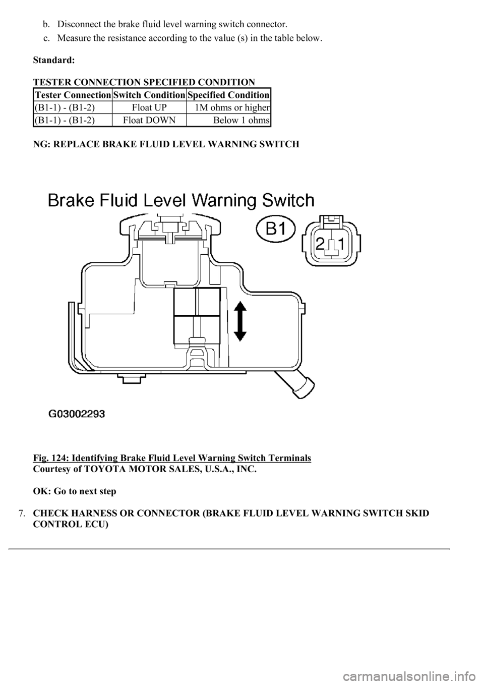
b. Disconnect the brake fluid level warning switch connector.
c. Measure the resistance according to the value (s) in the table below.
Standard:
TESTER CONNECTION SPECIFIED CONDITION
NG: REPLACE BRAKE FLUID LEVEL WARNING SWITCH
Fig. 124: Identifying Brake Fluid Level Warning Switch Terminals
Courtesy of TOYOTA MOTOR SALES, U.S.A., INC.
OK: Go to next step
7.CHECK HARNESS OR CONNECTOR (BRAKE FLUID LEVEL WARNING SWITCH SKID
CONTROL ECU)
Tester ConnectionSwitch ConditionSpecified Condition
(B1-1) - (B1-2)Float UP1M ohms or higher
(B1-1) - (B1-2)Float DOWNBelow 1 ohms
Page 178 of 4500
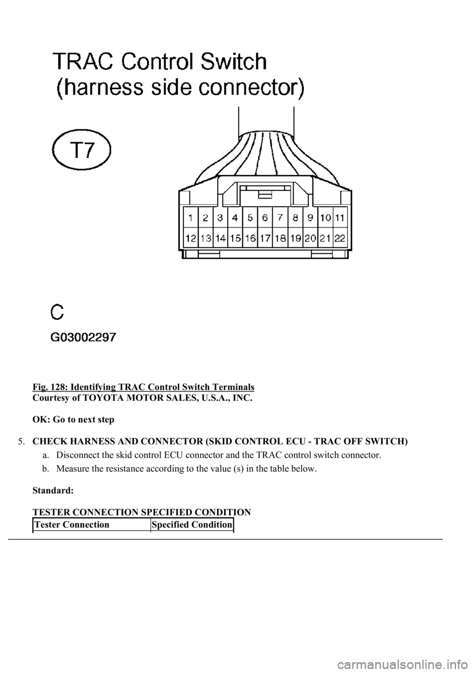
Fig. 128: Identifying TRAC Control Switch Terminals
Courtesy of TOYOTA MOTOR SALES, U.S.A., INC.
OK: Go to next step
5.CHECK HARNESS AND CONNECTOR (SKID CONTROL ECU - TRAC OFF SWITCH)
a. Disconnect the skid control ECU connector and the TRAC control switch connector.
b. Measure the resistance according to the value (s) in the table below.
Standard:
TESTER CONNECTION SPECIFIED CONDITION
Tester ConnectionSpecified Condition
Page 188 of 4500
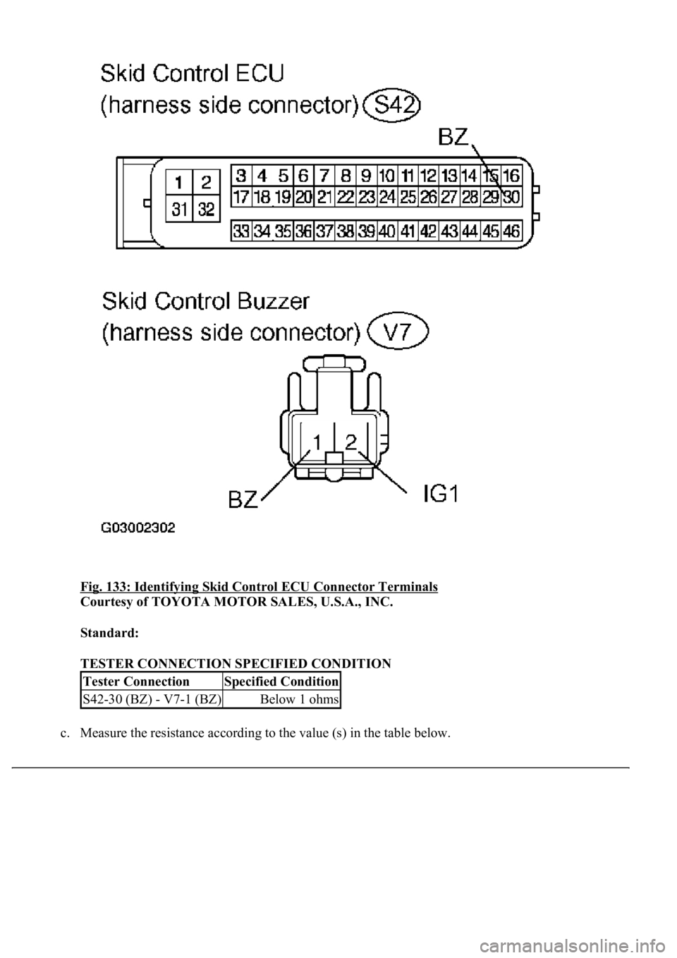
Fig. 133: Identifying Skid Control ECU Connector Terminals
Courtesy of TOYOTA MOTOR SALES, U.S.A., INC.
Standard:
TESTER CONNECTION SPECIFIED CONDITION
c. Measure the resistance accordin
g to the value (s) in the table below.
Tester ConnectionSpecified Condition
S42-30 (BZ) - V7-1 (BZ)Below 1 ohms
Page 194 of 4500
OK: Go to next step
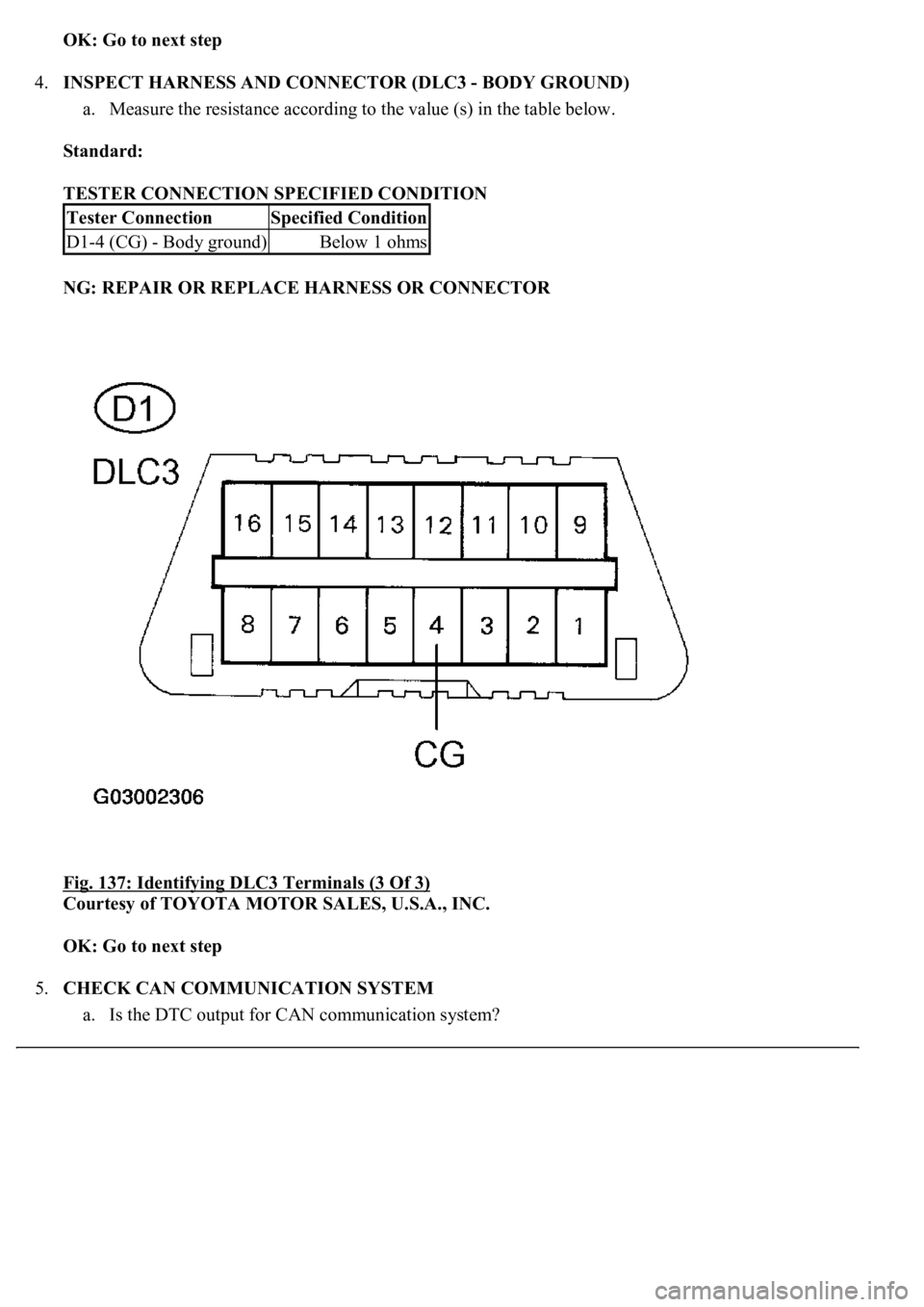
4.INSPECT HARNESS AND CONNECTOR (DLC3 - BODY GROUND)
a. Measure the resistance according to the value (s) in the table below.
Standard:
TESTER CONNECTION SPECIFIED CONDITION
NG: REPAIR OR REPLACE HARNESS OR CONNECTOR
Fig. 137: Identifying DLC3 Terminals (3 Of 3)
Courtesy of TOYOTA MOTOR SALES, U.S.A., INC.
OK: Go to next step
5.CHECK CAN COMMUNICATION SYSTEM
a. Is the DTC output for CAN communication s
ystem?
Tester ConnectionSpecified Condition
D1-4 (CG) - Body ground)Below 1 ohms
Page 197 of 4500
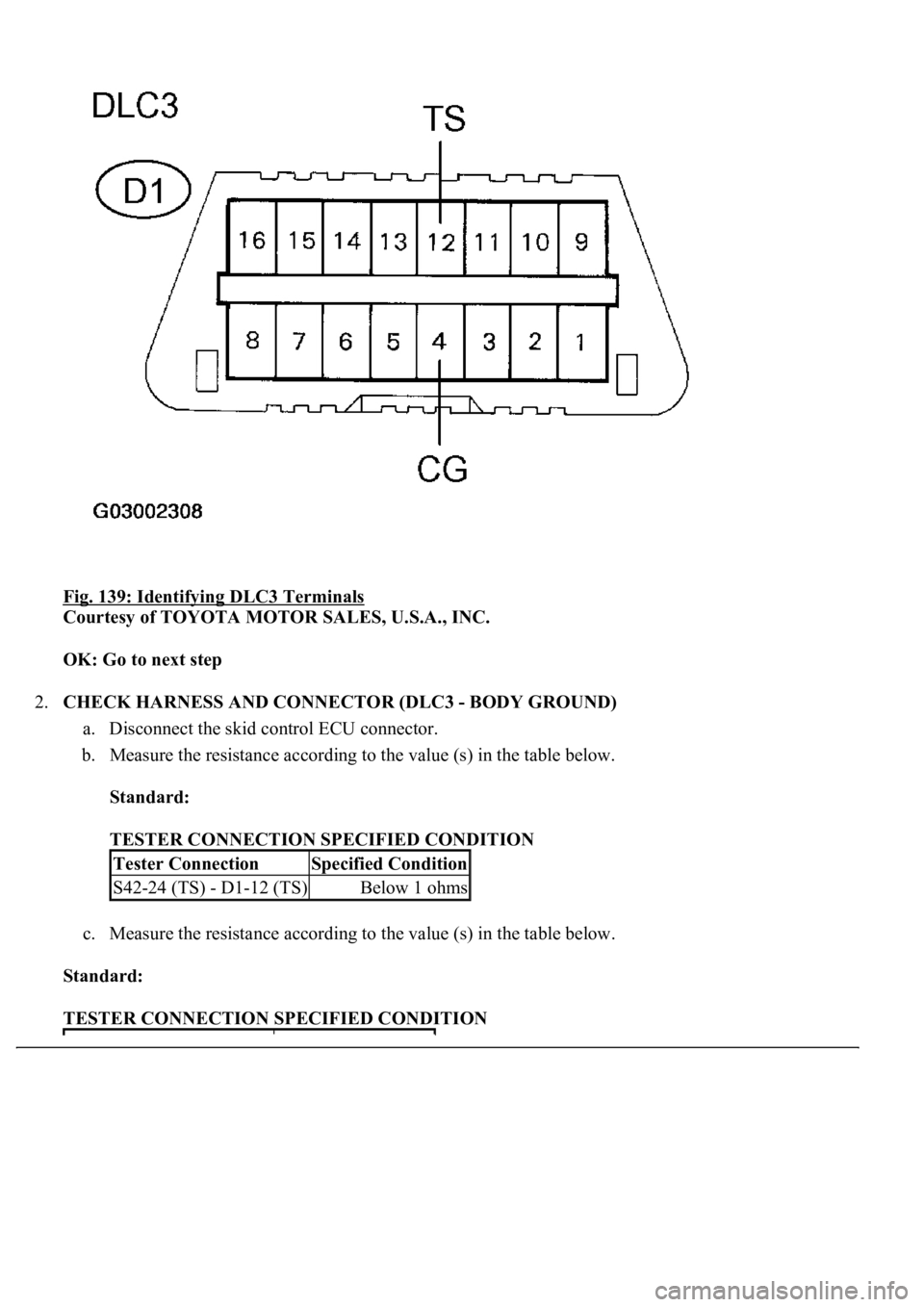
Fig. 139: Identifying DLC3 Terminals
Courtesy of TOYOTA MOTOR SALES, U.S.A., INC.
OK: Go to next step
2.CHECK HARNESS AND CONNECTOR (DLC3 - BODY GROUND)
a. Disconnect the skid control ECU connector.
b. Measure the resistance according to the value (s) in the table below.
Standard:
TESTER CONNECTION SPECIFIED CONDITION
c. Measure the resistance according to the value (s) in the table below.
Standard:
TESTER CONNECTION SPECIFIED CONDITION
Tester ConnectionSpecified Condition
S42-24 (TS) - D1-12 (TS)Below 1 ohms
Page 200 of 4500
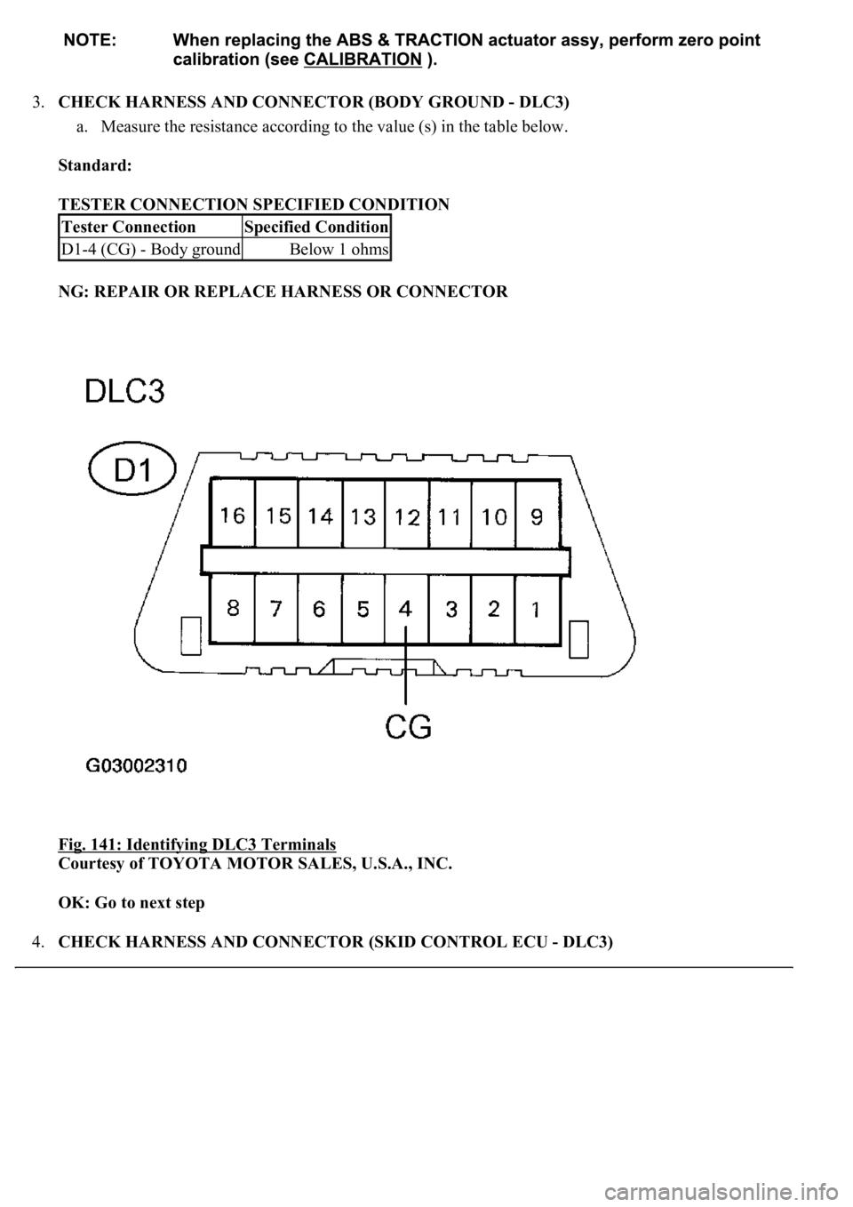
3.CHECK HARNESS AND CONNECTOR (BODY GROUND - DLC3)
a. Measure the resistance according to the value (s) in the table below.
Standard:
TESTER CONNECTION SPECIFIED CONDITION
NG: REPAIR OR REPLACE HARNESS OR CONNECTOR
Fig. 141: Identifying DLC3 Terminals
Courtesy of TOYOTA MOTOR SALES, U.S.A., INC.
OK: Go to next step
4.CHECK HARNESS AND CONNECTOR (SKID CONTROL ECU - DLC3)
Tester ConnectionSpecified Condition
D1-4 (CG) - Body groundBelow 1 ohms

