LEXUS LS430 2003 Factory User Guide
LS430 2003
LEXUS
LEXUS
https://www.carmanualsonline.info/img/36/57050/w960_57050-0.png
LEXUS LS430 2003 Factory User Guide
Page 2966 of 4500
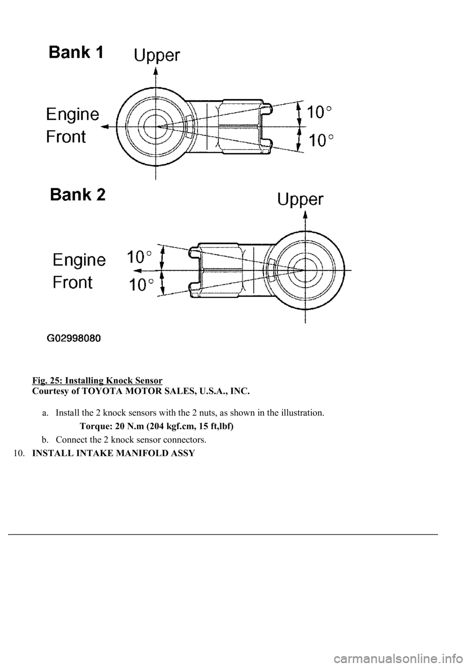
Fig. 25: Installing Knock Sensor
Courtesy of TOYOTA MOTOR SALES, U.S.A., INC.
a. Install the 2 knock sensors with the 2 nuts, as shown in the illustration.
Torque: 20 N.m (204 kgf.cm, 15 ft,lbf)
b. Connect the 2 knock sensor connectors.
10.INSTALL INTAKE MANIFOLD ASSY
Page 2967 of 4500
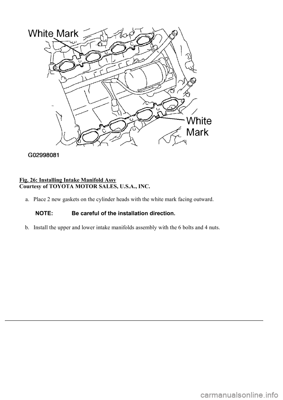
Fig. 26: Installing Intake Manifold Assy
Courtesy of TOYOTA MOTOR SALES, U.S.A., INC.
a. Place 2 new gaskets on the cylinder heads with the white mark facing outward.
b. Install the upper and lower intake manifolds assembly with the 6 bolts and 4 nuts.
Page 2968 of 4500
Fig. 27: Installing Upper And Lower Intake Manifolds Assembly
Courtesy of TOYOTA MOTOR SALES, U.S.A., INC.
Torque: 18 N.m (185 kgf.cm, 13 ft.lbf)
c. Connect the 8 injector connectors.
d. Install the engine wire protector (rear side) with the 2 bolts.
Page 2971 of 4500
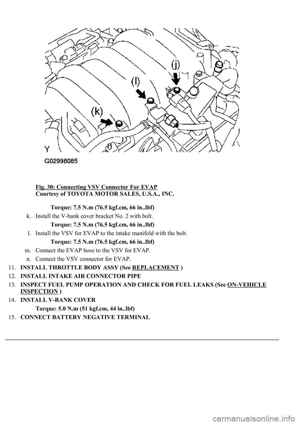
Fig. 30: Connecting VSV Connector For EVAP
Courtesy of TOYOTA MOTOR SALES, U.S.A., INC.
Torque: 7.5 N.m (76.5 kgf.cm, 66 in..lbf)
k. Install the V-bank cover bracket No. 2 with bolt.
Torque: 7.5 N.m (76.5 kgf.cm, 66 in..lbf)
l. Install the VSV for EVAP to the intake manifold with the bolt.
Torque: 7.5 N.m (76.5 kgf.cm, 66 in..lbf)
m. Connect the EVAP hose to the VSV for EVAP.
n. Connect the VSV connector for EVAP.
11.INSTALL THROTTLE BODY ASSY (See REPLACEMENT
)
12.INSTALL INTAKE AIR CONNECTOR PIPE
13.INSPECT FUEL PUMP OPERATION AND CHECK FOR FUEL LEAKS (See ON
-VEHICLE
INSPECTION )
14.INSTALL V-BANK COVER
Torque: 5.0 N.m (51 kgf.cm, 44 in..lbf)
15.CONNECT BATTERY NEGATIVE TERMINAL
Page 3319 of 4500
2. Turn the crankshaft damper bolt to gain access to each bolt.
3. Hold the crankshaft damper bolt with a wrench, and remove the 6 bolts.
b. Remove the 10 bolts and ground strap.
c. Remove the transmission together with the torque converter clutch from the engine.
Fig. 39: Removing Flywheel Housing Under Cover
Courtesy of TOYOTA MOTOR SALES, U.S.A., INC.
48.REMOVE DRIVE PLATE & RING GEAR SUB-ASSY
a. Remove the 8 bolts, rear spacer, ring gear and front spacer.
49.INSTALL ENGINE STAND
50.REMOVE THROTTLE BODY ASSY (See REPLACEMENT
)
51.REMOVE INTAKE MANIFOLD ASSY
a. Disconnect the VSV connector for EVAP.
b. Disconnect the EVAP hose from the VSV for EVAP.
c. Remove the bolt, disconnect the VSV for EVAP from the upper intake manifold.
d. Remove the bolt and V-bank cover bracket No. 2.
e. Remove the bolt and V-
bank cover bracket No. 3.
Page 3320 of 4500
Fig. 40: Removing Intake Manifold Assy
Courtesy of TOYOTA MOTOR SALES, U.S.A., INC.
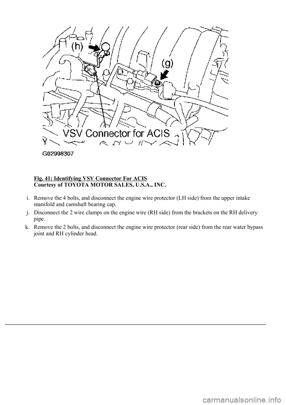
f. Disconnect the VSV connector for ACIS.
g. Remove the bolt and V-bank cover bracket No. 1.
h. Remove the bolt and V-
bank cover fastener.
Page 3321 of 4500
Fig. 41: Identifying VSV Connector For ACIS
Courtesy of TOYOTA MOTOR SALES, U.S.A., INC.
i. Remove the 4 bolts, and disconnect the engine wire protector (LH side) from the upper intake
manifold and camshaft bearing cap.
j. Disconnect the 2 wire clamps on the engine wire (RH side) from the brackets on the RH delivery
pipe.
k. Remove the 2 bolts, and disconnect the engine wire protector (rear side) from the rear water bypass
joint and RH cylinder head.
Page 3323 of 4500
Fig. 42: Disconnecting Engine Wire Protector (LH Side) From Upper Intake Manifold
Courtesy of TOYOTA MOTOR SALES, U.S.A., INC.
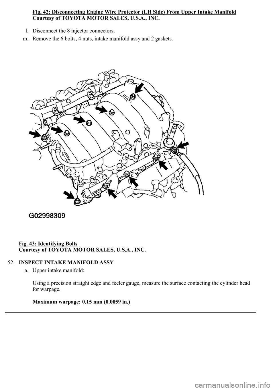
l. Disconnect the 8 injector connectors.
m. Remove the 6 bolts, 4 nuts, intake manifold assy and 2 gaskets.
Fig. 43: Identifying Bolts
Courtesy of TOYOTA MOTOR SALES, U.S.A., INC.
52.INSPECT INTAKE MANIFOLD ASSY
a. Upper intake manifold:
Using a precision straight edge and feeler gauge, measure the surface contacting the cylinder head
for warpage.
Maximum warpage: 0.15 mm (0.0059 in.)
Page 3324 of 4500
If the warpage is greater than the maximum, replace the manifold.
Fig. 44: Measuring Surface Contacting Cylinder Head
Courtesy of TOYOTA MOTOR SALES, U.S.A., INC.
b. Lower intake manifold Using a precision straight edge and feeler gauge, measure the surface
contacting the cylinder head for warpage.
Maximum warpage: 0.15 mm (0.0059 in.)
If the warpa
ge is greater than the maximum, replace the manifold.
Page 3325 of 4500
Fig. 45: Identifying Lower Intake Manifold
Courtesy of TOYOTA MOTOR SALES, U.S.A., INC.
53.REMOVE STARTER ASSY (See REPLACEMENT
)