LEXUS LS430 2003 Factory Owner's Manual
LS430 2003
LEXUS
LEXUS
https://www.carmanualsonline.info/img/36/57050/w960_57050-0.png
LEXUS LS430 2003 Factory Owner's Manual
Page 3342 of 4500
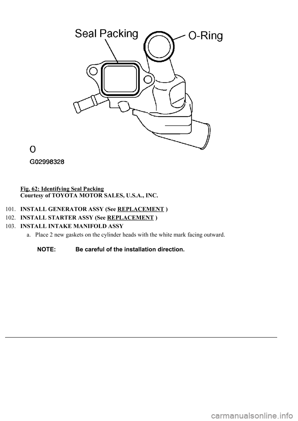
Fig. 62: Identifying Seal Packing
Courtesy of TOYOTA MOTOR SALES, U.S.A., INC.
101.INSTALL GENERATOR ASSY (See REPLACEMENT
)
102.INSTALL STARTER ASSY (See REPLACEMENT
)
103.INSTALL INTAKE MANIFOLD ASSY
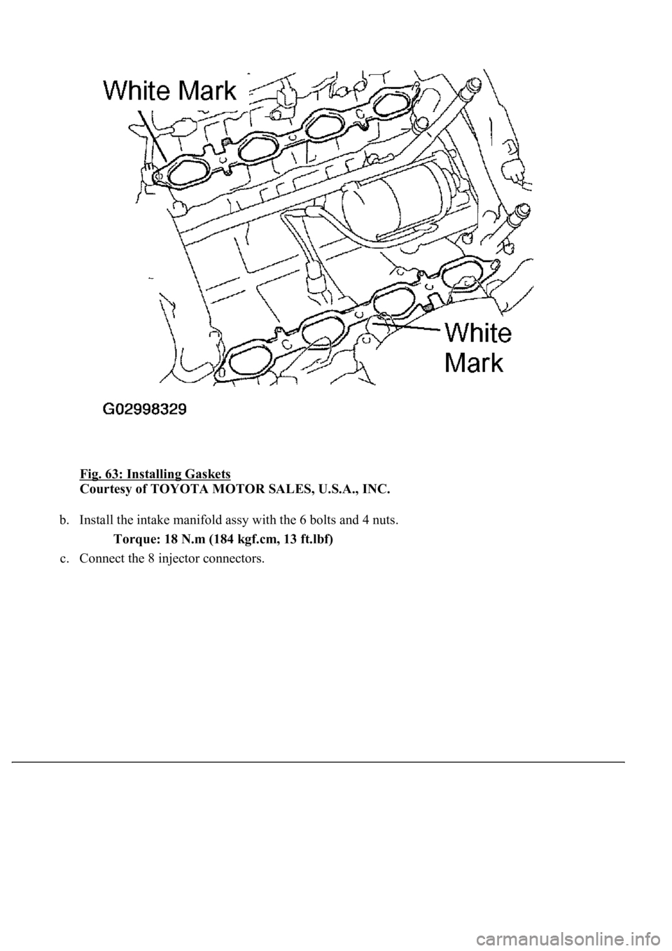
a. Place 2 new gaskets on the cylinder heads with the white mark facing outward.
Page 3343 of 4500
Fig. 63: Installing Gaskets
Courtesy of TOYOTA MOTOR SALES, U.S.A., INC.
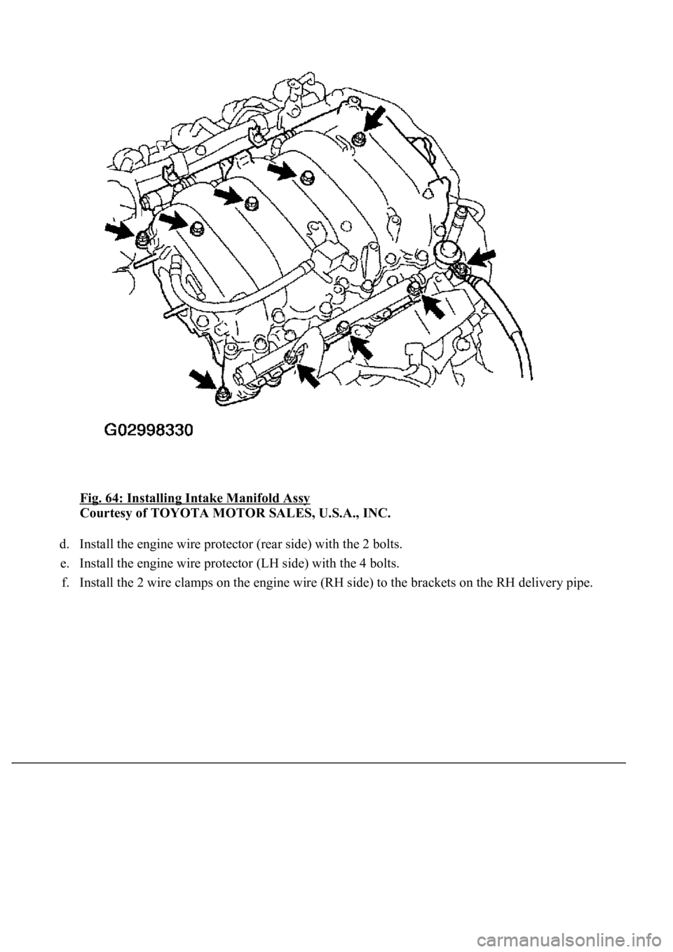
b. Install the intake manifold assy with the 6 bolts and 4 nuts.
Torque: 18 N.m (184 kgf.cm, 13 ft.lbf)
c. Connect the 8 in
jector connectors.
Page 3344 of 4500
Fig. 64: Installing Intake Manifold Assy
Courtesy of TOYOTA MOTOR SALES, U.S.A., INC.
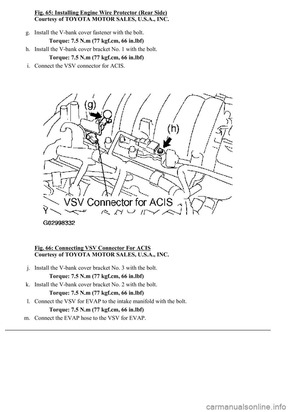
d. Install the engine wire protector (rear side) with the 2 bolts.
e. Install the engine wire protector (LH side) with the 4 bolts.
f. Install the 2 wire clamps on the en
gine wire (RH side) to the brackets on the RH delivery pipe.
Page 3346 of 4500
Fig. 65: Installing Engine Wire Protector (Rear Side)
Courtesy of TOYOTA MOTOR SALES, U.S.A., INC.
g. Install the V-bank cover fastener with the bolt.
Torque: 7.5 N.m (77 kgf.cm, 66 in.lbf)
h. Install the V-bank cover bracket No. 1 with the bolt.
Torque: 7.5 N.m (77 kgf.cm, 66 in.lbf)
i. Connect the VSV connector for ACIS.
Fig. 66: Connecting VSV Connector For ACIS
Courtesy of TOYOTA MOTOR SALES, U.S.A., INC.
j. Install the V-bank cover bracket No. 3 with the bolt.
Torque: 7.5 N.m (77 kgf.cm, 66 in.lbf)
k. Install the V-bank cover bracket No. 2 with the bolt.
Torque: 7.5 N.m (77 kgf.cm, 66 in.lbf)
l. Connect the VSV for EVAP to the intake manifold with the bolt.
Torque: 7.5 N.m (77 kgf.cm, 66 in.lbf)
m. Connect the EVAP hose to the VSV for EVAP.
Page 3555 of 4500
Fig. 271: Removing Upper And Lower Intake Manifold Assembly
Courtesy of TOYOTA MOTOR SALES, U.S.A., INC.
13.INSTALL CAMSHAFT TIMING PULLEY SUB-ASSY LH
a. Align the camshaft timing tube knock pin with the knock pin groove of the timing pulley.
b. Attach the timing pulley to the camshaft timing tube. Face the timing pulley's "L" mark forward.
c. Hold the hexagon wrench head portion of the camshaft, and install the 4 pulley bolts.
Torque: 7.5 N.m (77 kgf.cm, 66 in..lbf)
14.INSTALL CYLINDER HEAD COVER SUB-ASSY LH (See REPLACEMENT
)
15.INSTALL TIMING BELT (See REPLACEMENT
)
REPLACEMENT
Page 3556 of 4500
1.WORK FOR PREVENTING GASOLINE FROM SPILLING OUT (See PRECAUTION )
2.REMOVE CAMSHAFT (See REPLACEMENT
)
3.REMOVE THROTTLE BODY ASSY (See REPLACEMENT
)
4.REMOVE V-BANK COVER BRACKET NO.1
5.REMOVE V-BANK COVER BRACKET NO.2
6.REMOVE V-BANK COVER BRACKET NO.3
7.REMOVE V-VANK COVER BRACKET NO.4
8.REMOVE VACUUM SWITCHING VALVE ASSY
9.DISCONNECT FUEL PIPE SUB-ASSY NO.2 (See REPLACEMENT
)
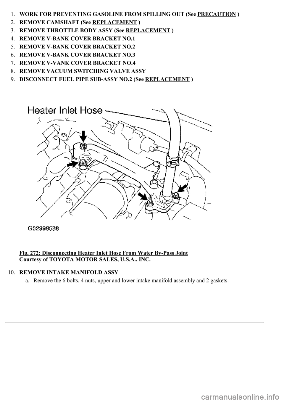
<0029004c004a001100030015001a0015001d00030027004c00560046005200510051004800460057004c0051004a0003002b004800440057004800550003002c0051004f004800570003002b005200560048000300290055005200500003003a0044005700
48005500030025005c[
-Pass Joint
Courtesy of TOYOTA MOTOR SALES, U.S.A., INC.
10.REMOVE INTAKE MANIFOLD ASSY
a. Remove the 6 bolts, 4 nuts, upper and lower intake manifold assembl
y and 2 gaskets.
Page 3568 of 4500
Fig. 284: Placing Gaskets On Cylinder Heads
Courtesy of TOYOTA MOTOR SALES, U.S.A., INC.
23.INSTALL INTAKE MANIFOLD ASSY
a. Place 2 new gaskets on the cylinder heads with the white mark facing outward.
Page 3569 of 4500
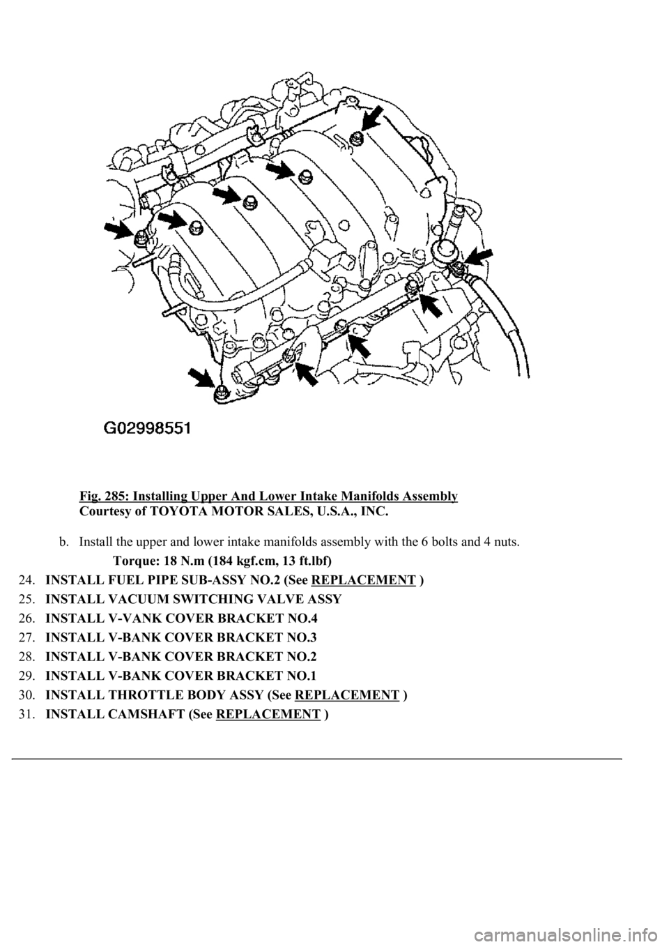
Fig. 285: Installing Upper And Lower Intake Manifolds Assembly
Courtesy of TOYOTA MOTOR SALES, U.S.A., INC.
b. Install the upper and lower intake manifolds assembly with the 6 bolts and 4 nuts.
Torque: 18 N.m (184 kgf.cm, 13 ft.lbf)
24.INSTALL FUEL PIPE SUB-ASSY NO.2 (See REPLACEMENT
)
25.INSTALL VACUUM SWITCHING VALVE ASSY
26.INSTALL V-VANK COVER BRACKET NO.4
27.INSTALL V-BANK COVER BRACKET NO.3
28.INSTALL V-BANK COVER BRACKET NO.2
29.INSTALL V-BANK COVER BRACKET NO.1
30.INSTALL THROTTLE BODY ASSY (See REPLACEMENT
)
31.INSTALL CAMSHAFT (See REPLACEMENT
)
Page 3571 of 4500
Fig. 286: Removing Upper And Lower Intake Manifold Assembly
Courtesy of TOYOTA MOTOR SALES, U.S.A., INC.
10.REMOVE INTAKE MANIFOLD ASSY
a. Remove the 6 bolts, 4 nuts, upper and lower intake manifold assembly and 2 gaskets.
11.REMOVE WATER BYPASS JOINT RR
a. Disconnect the heater inlet hose from the water bypass joint.
b. Remove the 4 nuts, water bypass joint and 2 gaskets.
Fig. 287: Disconnecting Heater Inlet Hose From Water By
-Pass Joint
Courtesy of TOYOTA MOTOR SALES, U.S.A., INC.
12.REMOVE WATER INLET HOUSING
a. Remove the 2 bolts and inlet housing.
13.REMOVE WATER BYPASS JOINT FR
a. Disconnect the ECT sensor connector.
b. Remove the 4 nuts, water bypass joint and 2 gaskets.
Page 3582 of 4500
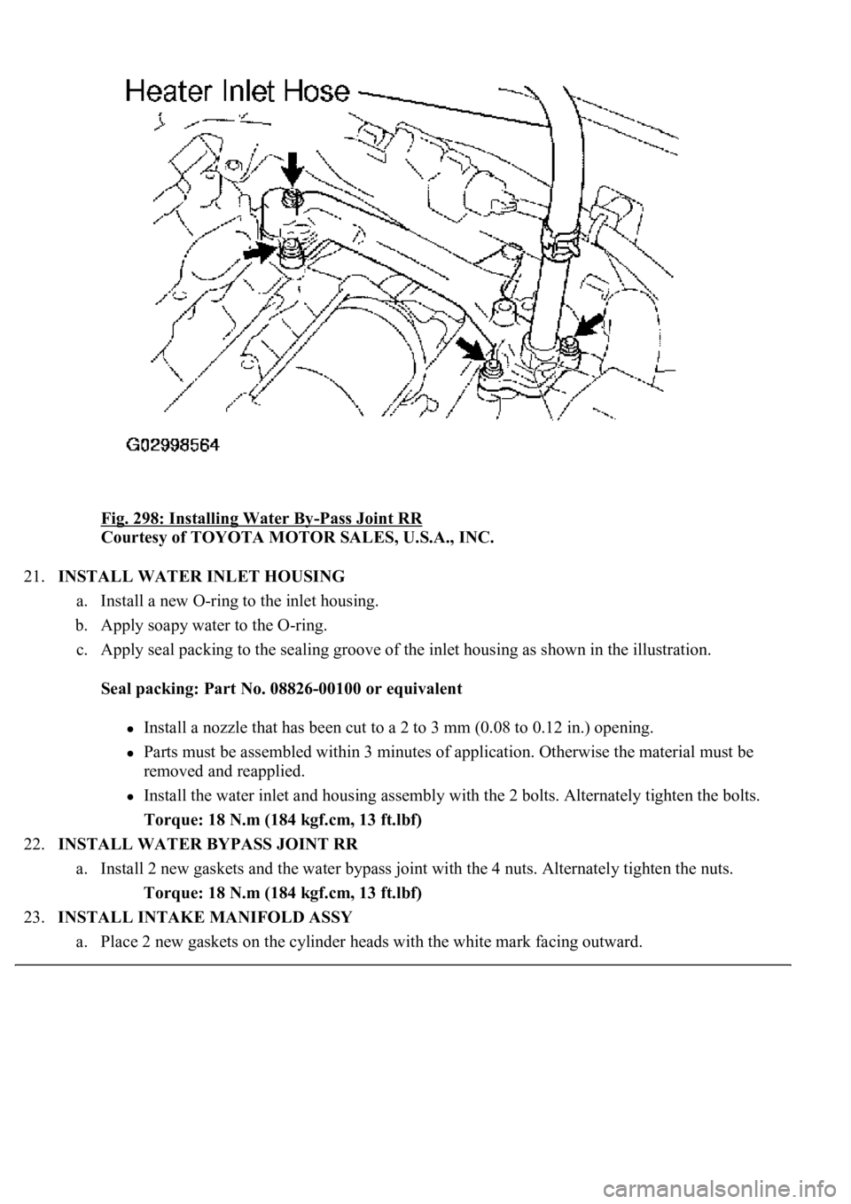
Fig. 298: Installing Water By-Pass Joint RR
Courtesy of TOYOTA MOTOR SALES, U.S.A., INC.
21.INSTALL WATER INLET HOUSING
a. Install a new O-ring to the inlet housing.
b. Apply soapy water to the O-ring.
c. Apply seal packing to the sealing groove of the inlet housing as shown in the illustration.
Seal packing: Part No. 08826-00100 or equivalent
<002c0051005600570044004f004f00030044000300510052005d005d004f004800030057004b004400570003004b00440056000300450048004800510003004600580057000300570052000300440003001500030057005200030016000300500050000300
0b001300110013001b00030057005200030013001100140015[ in.) opening.
Parts must be assembled within 3 minutes of application. Otherwise the material must be
removed and reapplied.
Install the water inlet and housing assembly with the 2 bolts. Alternately tighten the bolts.
Torque: 18 N.m (184 kgf.cm, 13 ft.lbf)
22.INSTALL WATER BYPASS JOINT RR
a. Install 2 new gaskets and the water bypass joint with the 4 nuts. Alternately tighten the nuts.
Torque: 18 N.m (184 kgf.cm, 13 ft.lbf)
23.INSTALL INTAKE MANIFOLD ASSY
a. Place 2 new gaskets on the cylinder heads with the white mark facing outward.