check engine light LEXUS LS430 2003 Factory User Guide
[x] Cancel search | Manufacturer: LEXUS, Model Year: 2003, Model line: LS430, Model: LEXUS LS430 2003Pages: 4500, PDF Size: 87.45 MB
Page 1022 of 4500
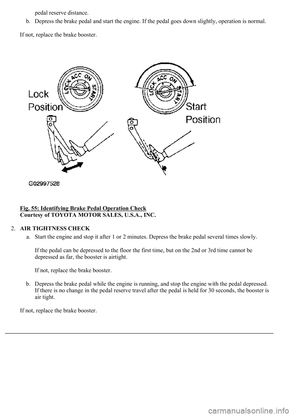
pedal reserve distance.
b. Depress the brake pedal and start the engine. If the pedal goes down slightly, operation is normal.
If not, replace the brake booster.
Fig. 55: Identifying Brake Pedal Operation Check
Courtesy of TOYOTA MOTOR SALES, U.S.A., INC.
2.AIR TIGHTNESS CHECK
a. Start the engine and stop it after 1 or 2 minutes. Depress the brake pedal several times slowly.
If the pedal can be depressed to the floor the first time, but on the 2nd or 3rd time cannot be
depressed as far, the booster is airtight.
If not, replace the brake booster.
b. Depress the brake pedal while the engine is running, and stop the engine with the pedal depressed.
If there is no change in the pedal reserve travel after the pedal is held for 30 seconds, the booster is
air tight.
If not, replace the brake booster.
Page 1762 of 4500
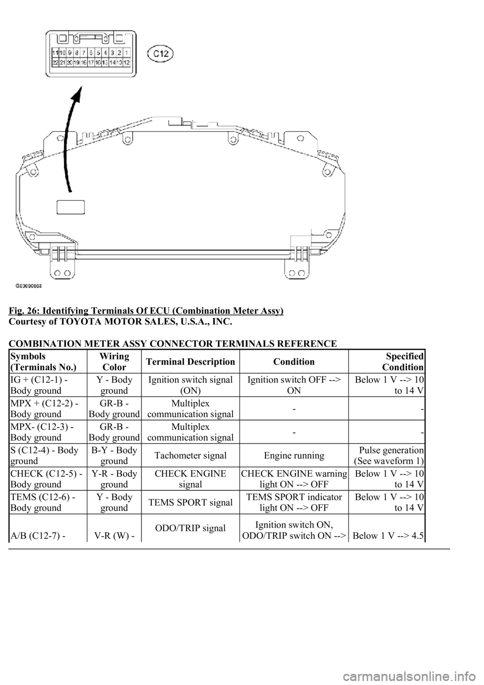
Fig. 26: Identifying Terminals Of ECU (Combination Meter Assy)
Courtesy of TOYOTA MOTOR SALES, U.S.A., INC.
COMBINATION METER ASSY CONNECTOR TERMINALS REFERENCE
Symbols
(Terminals No.)Wiring
ColorTerminal DescriptionConditionSpecified
Condition
IG + (C12-1) -
Body groundY - Body
groundIgnition switch signal
(ON)Ignition switch OFF -->
ONBelow 1 V --> 10
to 14 V
MPX + (C12-2) -
Body groundGR-B -
Body groundMultiplex
communication signal--
MPX- (C12-3) -
Body groundGR-B -
Body groundMultiplex
communication signal--
S (C12-4) - Body
groundB-Y - Body
groundTachometer signalEngine runningPulse generation
(See waveform 1)
CHECK (C12-5) -
Body groundY-R - Body
groundCHECK ENGINE
signalCHECK ENGINE warning
light ON --> OFFBelow 1 V --> 10
to 14 V
TEMS (C12-6) -
Body groundY - Body
groundTEMS SPORT signalTEMS SPORT indicator
light ON --> OFFBelow 1 V --> 10
to 14 V
A/B (C12-7) - V-R (W) - ODO/TRIP signalIgnition switch ON,
ODO/TRIP switch ON -->
Below 1 V --> 4.5
Page 1781 of 4500
ECT PWR INDICIndicat. Lamp ECT PWR (OFF/ON)Confirm that the vehicle is stopped
and engine idling
Rr FOG INDICIndicat. Lamp Rr FOG (OFF/ON)Confirm that the vehicle is stopped
and engine idling
OIL LEVEL WARNIndicat. Lamp OIL LEVEL (OFF/ON)Confirm that the vehicle is stopped
and engine idling
Rr LIGHT INDICIndicat. Lamp Rr Light (OFF/ON)Confirm that the vehicle is stopped
and engine idling
VSC WARNIndicat. Lamp VSC (OFF/ON)Confirm that the vehicle is stopped
and engine idling
ARS WARNIndicat. Lamp ARS (OFF/ON)Confirm that the vehicle is stopped
and engine idling
MIL (ENGINE)Indicat. Lamp ENGINE (OFF/ON)Confirm that the vehicle is stopped
and engine idling
LOW WASHER
WARNIndicat. Lamp WASHER (OFF/ON)Confirm that the vehicle is stopped
and engine idling
ItemTest DetailsDiagnostic Note
SRS WARNIndicat. Lamp AIRBAG (OFF/ON)Confirm that the vehicle is stopped
and engine idling
HIGH BEAM INDICIndicat. Lamp BEAM (OFF/ON)Confirm that the vehicle is stopped
and engine idling
TURN INDIC-LIndicat. Lamp TURN L (OFF/ON)Confirm that the vehicle is stopped
and engine idling
TURN INDIC-RIndicat. Lamp TURN R (OFF/ON)Confirm that the vehicle is stopped
and engine idling
ABS WARNIndicat. Lamp ABS (OFF/ON)Confirm that the vehicle is stopped
and engine idling
TRC OFF INDICIndicat. Lamp TRAC (TRC) OFF
(OFF/ON)Confirm that the vehicle is stopped
and engine idling
SLIP INDICIndicat. Lamp SLIP (OFF/ON)Confirm that the vehicle is stopped
and engine idling
O/D OFF INDICIndicat. Lamp O/D OFF (OFF/ON)Confirm that the vehicle is stopped
and engine idling
ODO/TRIP DISPIndicat. ODO/TRIP DISPLAY (OFF/ON)Confirm that the vehicle is stopped
and engine idling
A/T OIL TEMPA/T OIL temperature operation (OFF/ON)Confirm that the vehicle is stopped
and engine idling
L-CRUISE DISPIndicat. Laser Cruise DISPLAY (OFF/ON)Confirm that the vehicle is stopped
and engine idling
L-CRS CHECK INDIndicat. Lamp L-CRUISE CHECK
(OFF/ON)Confirm that the vehicle is stopped
and engine idling
L-CRS READY INDIndicat. Lamp L-CRUISE READY
(OFF/ON)Confirm that the vehicle is stopped
and engine idling
Fr FOG INDICIndicat. Lamp Fr FOG (OFF/ON)Confirm that the vehicle is stopped
Page 2680 of 4500
6. Check the lock-up mechanism.
Drive in the D position (4th, 5th or 6th gear), at a steady speed (lock-up ON).
Lightly depress the accelerator pedal and check that the engine speed does not change
abruptly.
HINT:
There is no lock-up function in the 1st, 2nd and 3rd gears.
If there is a big jump in engine speed, there is no lock-up.
b. S position test
Shift to the S position, depress the accelerator pedal and check the following points:
1. Check shift operation.
While driving in the D position and 6th gear, shift into the S position and back to the D
position. Check that the gear change 6 --> 5 down-shift and 5 --> 6 up-shift can be
performed.
With the shift lever in the S position (while the vehicle is stopped), shift into the "+"
position to check that the shift position on the combination meter changes as follows: 1
--> 2, 2 --> 3, 3 --> 4, 4 --> 5 and 5 --> 6.
While driving in the 5(S) position and 4th gear (at a vehicle speed of approximately 55
to 65 km/h (34 to 40 mph)), shift into the "-" position and check if the 4th gear down-
shift occurs and the engine brake performs properly.
While driving in the 4(S) position and 4th gear (at a vehicle speed of approximately 30
to 40 km/h (19 to 25 mph)), shift into the "-" position and check if the 3rd gear down-
shift occurs and the engine brake performs properly.
While driving in the 3(S) position and 3rd gear (at a vehicle speed of approximately 20
to 30 km/h (12 to 19 mph)), shift into the "-" position and check if the 2nd gear down-
shift occurs and the engine brake performs properly.
<003a004b004c004f0048000300470055004c0059004c0051004a0003004c005100030057004b004800030015000b0036000c0003005300520056004c0057004c00520051000300440051004700030015005100470003004a0048004400550003000b004400
5700030044000300590048004b004c0046004f004800030056[peed of approximately 10
to 20 km/h (6 to 12 mph)), shift into the "-" position and check if the 1st gear down-
shift occurs and the engine brake performs properly.
HINT:
Manual shift (S position) is prohibited under either of the following conditions:
Down-shifting may cause engine overrun.
The driver continuously down-shifts. (Down-shifting to 1st gear may not be performed.)
c. R position test:
Shift into the R position, lightly depress the accelerator pedal, and check that the vehicle moves
backward without any abnormal noise or vibration.
Page 2759 of 4500
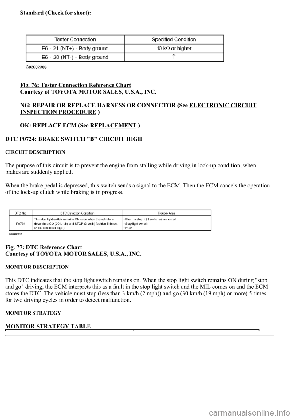
Standard (Check for short):
Fig. 76: Tester Connection Reference Chart
Courtesy of TOYOTA MOTOR SALES, U.S.A., INC.
NG: REPAIR OR REPLACE HARNESS OR CONNECTOR (See ELECTRONIC CIRCUIT
INSPECTION PROCEDURE )
OK: REPLACE ECM (See REPLACEMENT
)
DTC P0724: BRAKE SWITCH "B" CIRCUIT HIGH
CIRCUIT DESCRIPTION
The purpose of this circuit is to prevent the engine from stalling while driving in lock-up condition, when
brakes are suddenly applied.
When the brake pedal is depressed, this switch sends a signal to the ECM. Then the ECM cancels the operation
of the lock-up clutch while braking is in progress.
Fig. 77: DTC Reference Chart
Courtesy of TOYOTA MOTOR SALES, U.S.A., INC.
MONITOR DESCRIPTION
This DTC indicates that the stop light switch remains on. When the stop light switch remains ON during "stop
and go" driving, the ECM interprets this as a fault in the stop light switch and the MIL comes on and the ECM
stores the DTC. The vehicle must stop (less than 3 km/h (2 mph)) and go (30 km/h (19 mph) or more) 5 times
for two driving cycles in order to detect malfunction.
MONITOR STRATEGY
MONITOR STRATEGY TABLE
Page 2874 of 4500
a. Warm up the engine.
b. Turn the ignition switch off.
c. Connect the hand-held tester together with the CAN VIM (controller area network vehicle interface
module) to the DLC3.
d. Turn the ignition switch to the ON position.
e. Push the "ON" button of the hand-held tester.
f. Clear the DTC.
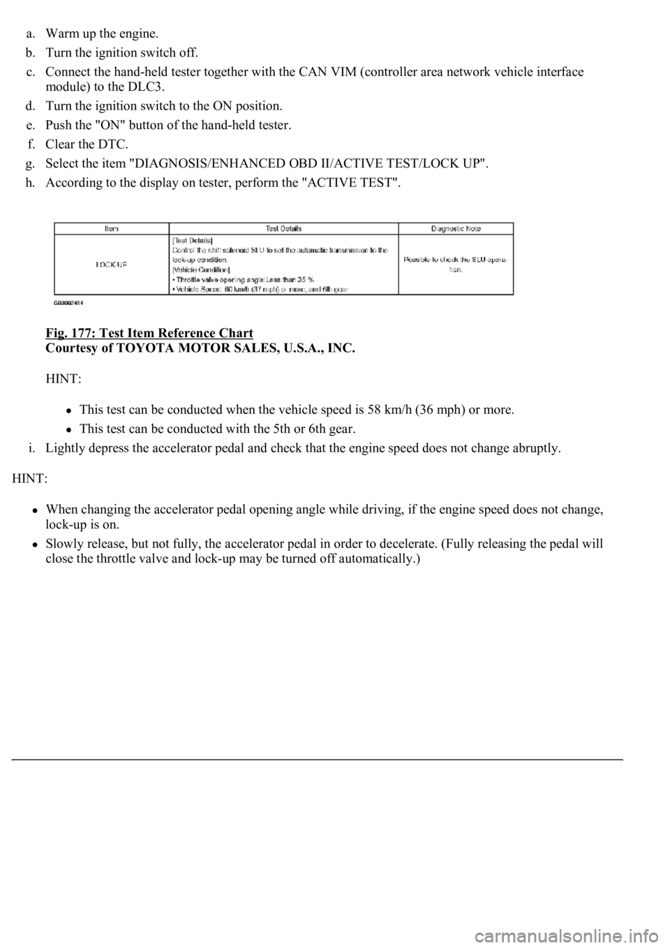
g. Select the item "DIAGNOSIS/ENHANCED OBD II/ACTIVE TEST/LOCK UP".
h. According to the display on tester, perform the "ACTIVE TEST".
Fig. 177: Test Item Reference Chart
Courtesy of TOYOTA MOTOR SALES, U.S.A., INC.
HINT:
This test can be conducted when the vehicle speed is 58 km/h (36 mph) or more.
This test can be conducted with the 5th or 6th gear.
i. Lightly depress the accelerator pedal and check that the engine speed does not change abruptly.
HINT:
When changing the accelerator pedal opening angle while driving, if the engine speed does not change,
lock-up is on.
Slowly release, but not fully, the accelerator pedal in order to decelerate. (Fully releasing the pedal will
close the throttle valve and loc
k-up may be turned off automatically.)
Page 3562 of 4500

Fig. 278: Tightening Cylinder Head Bolts
Courtesy of TOYOTA MOTOR SALES, U.S.A., INC.
18.INSTALL CYLINDER HEAD SUB-ASSY
a. Check that the cut part of the crankshaft timing pulley is in the position shown in the illustration,
and that the piston is below the TDC of compression.
b. Install the cylinder head together with the manifold RH to the cylinder block.
c. Apply a light coat of engine oil on the threads and under the head of the cylinder head bolts.
d. Put the washer on the bolt, and insert the bolt with washer into the cylinder head.
Page 3575 of 4500
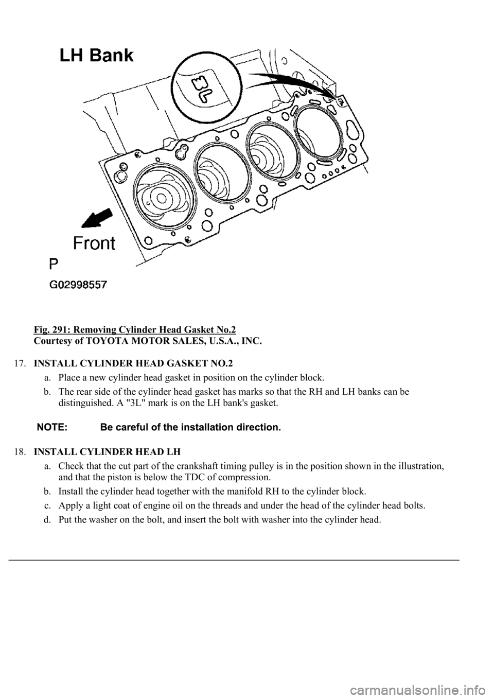
Fig. 291: Removing Cylinder Head Gasket No.2
Courtesy of TOYOTA MOTOR SALES, U.S.A., INC.
17.INSTALL CYLINDER HEAD GASKET NO.2
a. Place a new cylinder head gasket in position on the cylinder block.
b. The rear side of the cylinder head gasket has marks so that the RH and LH banks can be
distinguished. A "3L" mark is on the LH bank's gasket.
18.INSTALL CYLINDER HEAD LH
a. Check that the cut part of the crankshaft timing pulley is in the position shown in the illustration,
and that the piston is below the TDC of compression.
b. Install the cylinder head together with the manifold RH to the cylinder block.
c. Apply a light coat of engine oil on the threads and under the head of the cylinder head bolts.
d. Put the washer on the bolt, and insert the bolt with washer into the c
ylinder head.