warning light LEXUS LS430 2003 Factory User Guide
[x] Cancel search | Manufacturer: LEXUS, Model Year: 2003, Model line: LS430, Model: LEXUS LS430 2003Pages: 4500, PDF Size: 87.45 MB
Page 42 of 4500
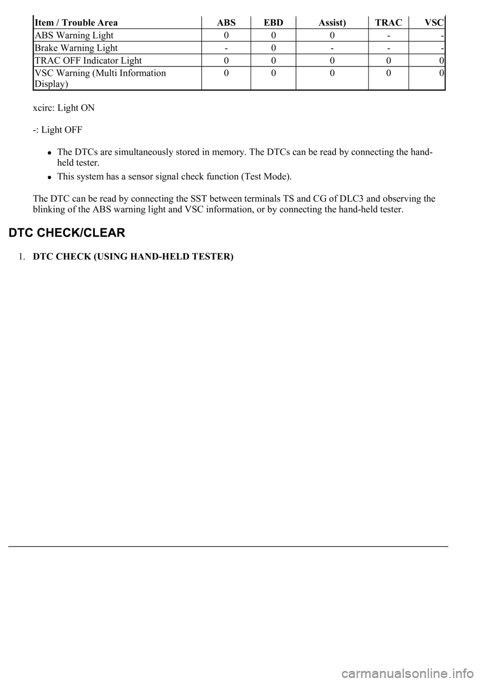
xcirc: Light ON
-: Light OFF
The DTCs are simultaneously stored in memory. The DTCs can be read by connecting the hand-
held tester.
This system has a sensor signal check function (Test Mode).
The DTC can be read by connecting the SST between terminals TS and CG of DLC3 and observing the
blinking of the ABS warning light and VSC information, or by connecting the hand-held tester.
1.DTC CHECK (USING HAND-HELD TESTER)
Item / Trouble AreaABSEBDAssist)TRACVSC
ABS Warning Light000--
Brake Warning Light-0---
TRAC OFF Indicator Light00000
VSC Warning (Multi Information
Display)00000
Page 44 of 4500
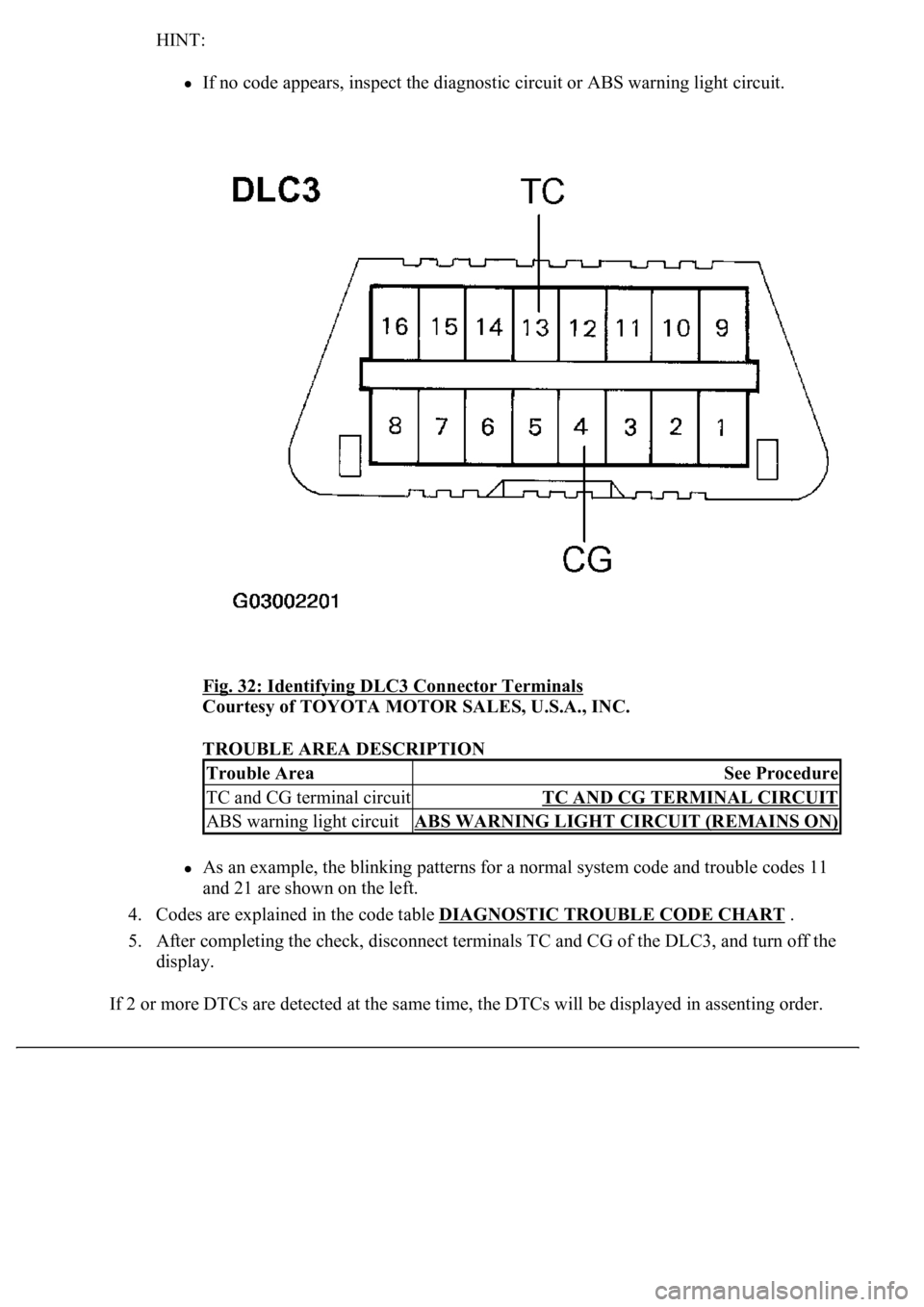
HINT:
If no code appears, inspect the diagnostic circuit or ABS warning light circuit.
Fig. 32: Identifying DLC3 Connector Terminals
Courtesy of TOYOTA MOTOR SALES, U.S.A., INC.
TROUBLE AREA DESCRIPTION
As an example, the blinking patterns for a normal system code and trouble codes 11
and 21 are shown on the left.
4. Codes are explained in the code table DIAGNOSTIC TROUBLE CODE CHART
.
5. After completing the check, disconnect terminals TC and CG of the DLC3, and turn off the
display.
If 2 or more DTCs are detected at the same time, the DTCs will be displayed in assenting order.
Trouble AreaSee Procedure
TC and CG terminal circuitTC AND CG TERMINAL CIRCUIT
ABS warning light circuitABS WARNING LIGHT CIRCUIT (REMAINS ON)
Page 47 of 4500
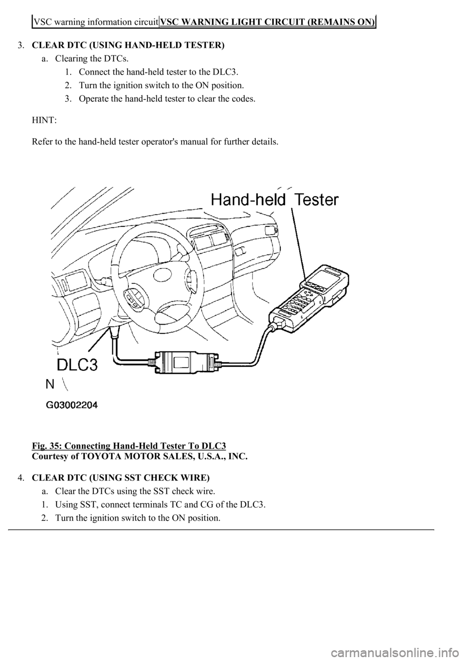
3.CLEAR DTC (USING HAND-HELD TESTER)
a. Clearing the DTCs.
1. Connect the hand-held tester to the DLC3.
2. Turn the ignition switch to the ON position.
3. Operate the hand-held tester to clear the codes.
HINT:
Refer to the hand-held tester operator's manual for further details.
Fig. 35: Connecting Hand
-Held Tester To DLC3
Courtesy of TOYOTA MOTOR SALES, U.S.A., INC.
4.CLEAR DTC (USING SST CHECK WIRE)
a. Clear the DTCs using the SST check wire.
1. Using SST, connect terminals TC and CG of the DLC3.
2. Turn the i
gnition switch to the ON position.
VSC warning information circuitVSC WARNING LIGHT CIRCUIT (REMAINS ON)
Page 48 of 4500
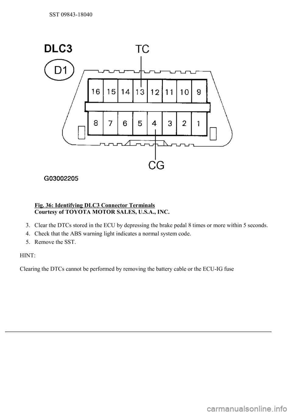
SST 09843-18040
Fig. 36: Identifying DLC3 Connector Terminals
Courtesy of TOYOTA MOTOR SALES, U.S.A., INC.
3. Clear the DTCs stored in the ECU by depressing the brake pedal 8 times or more within 5 seconds.
4. Check that the ABS warning light indicates a normal system code.
5. Remove the SST.
HINT:
Clearin
g the DTCs cannot be performed by removing the battery cable or the ECU-IG fuse
Page 55 of 4500
HINT:
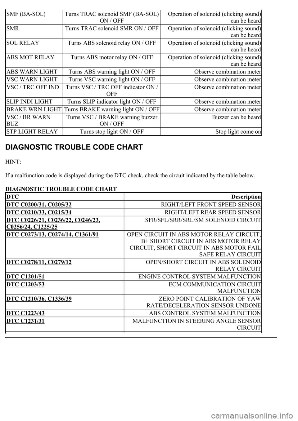
If a malfunction code is displayed during the DTC check, check the circuit indicated by the table below.
DIAGNOSTIC TROUBLE CODE CHART
SMF (BA-SOL)Turns TRAC solenoid SMF (BA-SOL)
ON / OFFOperation of solenoid (clicking sound)
can be heard
SMRTurns TRAC solenoid SMR ON / OFFOperation of solenoid (clicking sound)
can be heard
SOL RELAYTurns ABS solenoid relay ON / OFFOperation of solenoid (clicking sound)
can be heard
ABS MOT RELAYTurns ABS motor relay ON / OFFOperation of solenoid (clicking sound)
can be heard
ABS WARN LIGHTTurns ABS warning light ON / OFFObserve combination meter
VSC WARN LIGHTTurns VSC warning light ON / OFFObserve combination meter
VSC / TRC OFF INDTurns VSC / TRC OFF indicator ON /
OFFObserve combination meter
SLIP INDI LIGHTTurns SLIP indicator light ON / OFFObserve combination meter
BRAKE WRN LIGHTTurns BRAKE warning light ON / OFFObserve combination meter
VSC / BR WARN
BUZTurns VSC / BRAKE warning buzzer
ON / OFFBuzzer can be heard
STP LIGHT RELAYTurns stop light ON / OFFStop light come on
DTCDescription
DTC C0200/31, C0205/32RIGHT/LEFT FRONT SPEED SENSOR
DTC C0210/33, C0215/34RIGHT/LEFT REAR SPEED SENSOR
DTC C0226/21, C0236/22, C0246/23,
C0256/24, C1225/25
SFR/SFL/SRR/SRL/SM SOLENOID CIRCUIT
DTC C0273/13, C0274/14, C1361/91OPEN CIRCUIT IN ABS MOTOR RELAY CIRCUIT,
B+ SHORT CIRCUIT IN ABS MOTOR RELAY
CIRCUIT, SHORT CIRCUIT IN ABS MOTOR FAIL
SAFE RELAY CIRCUIT
DTC C0278/11, C0279/12OPEN/SHORT CIRCUIT IN ABS SOLENOID
RELAY CIRCUIT
DTC C1201/51ENGINE CONTROL SYSTEM MALFUNCTION
DTC C1203/53ECM COMMUNICATION CIRCUIT
MALFUNCTION
DTC C1210/36, C1336/39ZERO POINT CALIBRATION OF YAW
RATE/DECELERATION SENSOR UNDONE
DTC C1223/43ABS CONTROL SYSTEM MALFUNCTION
DTC C1231/31MALFUNCTION IN STEERING ANGLE SENSOR
CIRCUIT
Page 58 of 4500
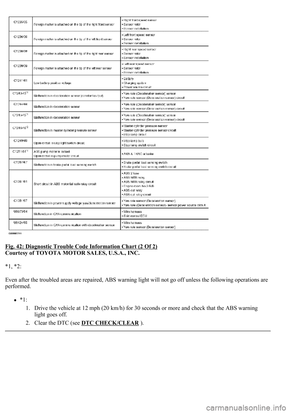
Fig. 42: Diagnostic Trouble Code Information Chart (2 Of 2)
Courtesy of TOYOTA MOTOR SALES, U.S.A., INC.
*1, *2:
Even after the troubled areas are repaired, ABS warning light w<004c004f004f00030051005200570003004a00520003005200490049000300580051004f00480056005600030057004b0048000300490052004f004f0052005a004c0051004a0003005200530048005500440057004c005200510056000300440055004800
03[
performed.
*1:
1. Drive the vehicle at 12 mph (20 km/h) for 30 seconds or more and check that the ABS warning
light goes off.
2. Clear the DTC (see DTC CHECK/CLEAR
).
Page 59 of 4500
*2:
1. Keep the vehicle in the stationary condition for 5 seconds or more and depress the brake pedal
lightly 2 or 3 times.
2. Drive the vehicle at the vehicle speed of 31 mph (50 km/h) and keep depressing the brake pedal
strongly for approximately 3 seconds.
3. Repeat the above operation 3 times or more and check that the ABS warning light goes off.
4. Clear the DTC (see DTC CHECK/CLEAR
).
HINT:
In some cases, the hand-held tester cannot be used when ABS warning light remains on.
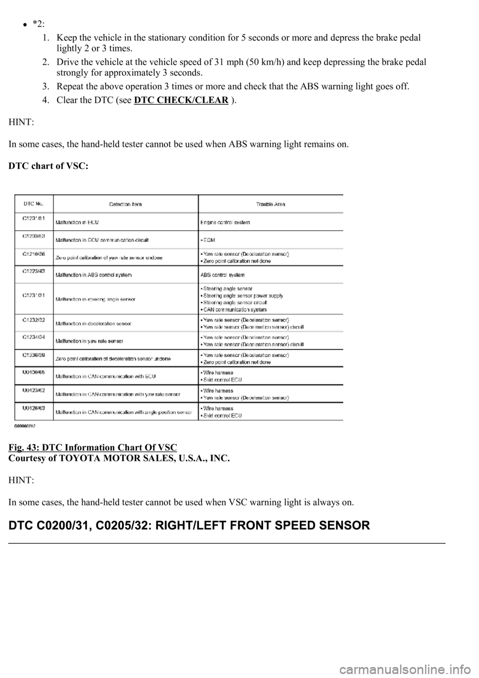
DTC chart of VSC:
Fig. 43: DTC Information Chart Of VSC
Courtesy of TOYOTA MOTOR SALES, U.S.A., INC.
HINT:
In some cases, the hand-held tester cannot be used when VSC warning light is always on.
Page 149 of 4500
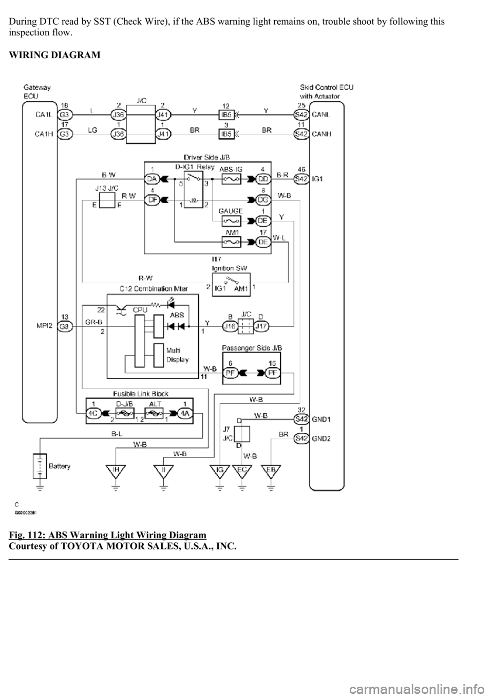
During DTC read by SST (Check Wire), if the ABS warning light remains on, trouble shoot by following this
inspection flow.
WIRING DIAGRAM
Fig. 112: ABS Warning Light Wiring Diagram
Courtesy of TOYOTA MOTOR SALES, U.S.A., INC.
Page 153 of 4500
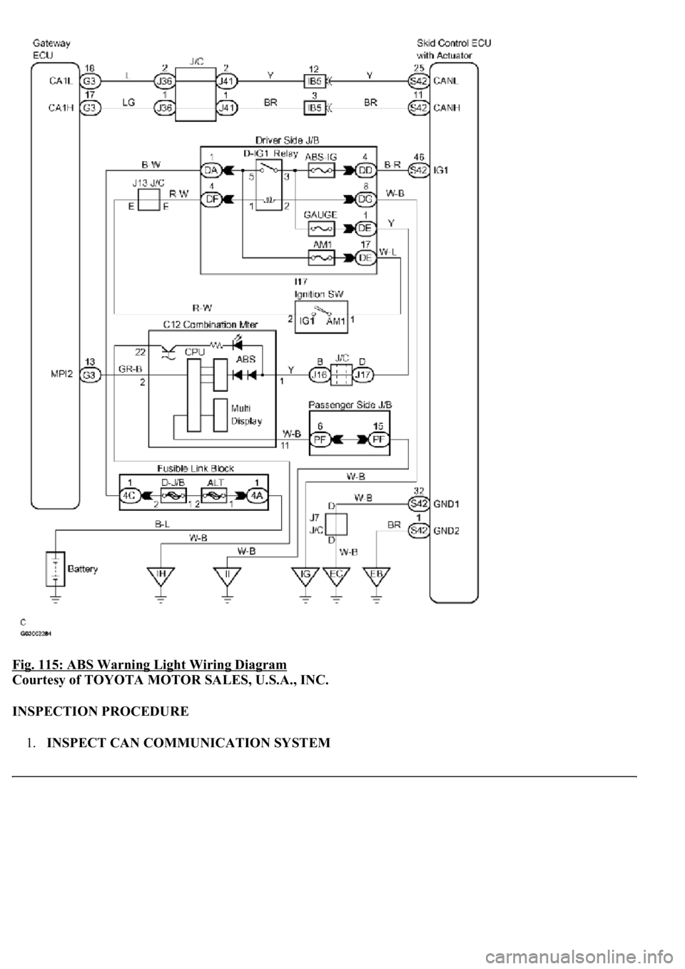
Fig. 115: ABS Warning Light Wiring Diagram
Courtesy of TOYOTA MOTOR SALES, U.S.A., INC.
INSPECTION PROCEDURE
1.INSPECT CAN COMMUNICATION SYSTEM
Page 154 of 4500

a. Is the DTC output for CAN communication system?
Result:
DTC OUTPUT DESCRIPTION
B: REPAIR CAN COMMUNICATION SYSTEM (SEE PRECAUTION
)
A: Go to next step
2.INSPECT MULTIPLEX COMMUNICATION SYSTEM
a. Is the DTC output for Multiplex communication system?
Result:
DTC OUTPUT DESCRIPTION
B: REPAIR MULTIPLEX COMMUNICATION SYSTEM (SEE DIAGNOSTIC TROUBLE
CODE CHART )
A: Go to next step
3.INSPECT ABS WARNING LIGHT
a. Connect the hand-held tester to the DLC3 and start the engine.
b. Select the item "ABS WARN LIGHT" in the ACTIVE TEST and operate the ABS warning light on
the hand-held tester.
VEHICLE CONDITION / TEST DETAILS
c. Check that "ON" and "OFF" of the ABS warning light can be shown on the combination meter by
the hand-held tester.
Standard:
Turn the ABS warning light ON or OFF in accordance with the hand-held tester.
NG: CHECK AND REPAIR ABS WARNING LIGHT CIRCUIT
OK: REPLACE ABS & TRACTION ACTUATOR ASSY (SEE REPLACEMENT
)
DTC is not outputA
DTC is outputB
DTC is not outputA
DTC is outputB
ItemVehicle Condition / Test DetailsDiagnostic Note
ABS WARN LIGHTTurns ABS warning light ON / OFFObserve combination meter