water pump LEXUS LS430 2003 Factory User Guide
[x] Cancel search | Manufacturer: LEXUS, Model Year: 2003, Model line: LS430, Model: LEXUS LS430 2003Pages: 4500, PDF Size: 87.45 MB
Page 3313 of 4500
13.DRAIN AUTOMATIC TRANSMISSION FLUID
14.REMOVE RADIATOR ASSY (See REPLACEMENT
)
15.DISCONNECT FUEL PIPE SUB-ASSY NO.2 (See REPLACEMENT
)
16.REMOVE FAN AND GENERATOR V BELT (See REPLACEMENT
)
17.DISCONNECT ENGINE WIRE
a. Disconnect the engine wire from the ECM box.
b. Remove the nut, and disconnect the generator wire from the generator.
c. Disconnect the wire for generator wire from the wire clamp on generator.
d. Remove the bolt, and disconnect the ground cable from the stay on the generator.
e. Remove the 2 bolts, and disconnect the PS oil hose from the No. 1 oil pan.
f. Remove the bolt, and disconnect the ground strap from the body.
18.DISCONNECT AIR HOSE NO.5
19.DISCONNECT FUEL VAPOR FEED HOSE NO.2
20.DISCONNECT HEATER WATER INLET HOSE A
21.DISCONNECT HEATER WATER OUTLET HOSE A (FROM HEATER UNIT)
22.DISCONNECT VANE PUMP OIL RESERVOIR ASSY
23.DISCONNECT VANE PUMP ASSY
a. Disconnect the 2 PS air hoses.
b. Remove the 2 screws and RH engine under cover.
c. Disconnect the PS oil pressure switch connector.
d. Remove the 2 bolts and nut, and disconnect the pump from the engine.
e. Support the pump securely.
24.DISCONNECT COOLER COMPRESSOR ASSY
a. Disconnect the compressor connector.
b. Disconnect the wire clamp from the wire bracket on the compressor.
c. Remove the bolt, nut and stay.
d. Remove the bolt, and disconnect the wire bracket from the compressor.
e. Remove the bolt, and disconnect the compressor from the engine.
f. Support the cooler compressor securely.
25.REMOVE FRONT FLOOR BRACE CENTER
a. Remove the 4 bolts and brace center.
26.REMOVE EXHAUST PIPE ASSY (See REPLACEMENT
)
27.REMOVE W/ CATALYST CONVERTER ASSY
28.REMOVE FRONT FLOOR HEAT INSULATOR NO.1
29.REMOVE PARKING BRAKE CABLE HEAT INSULATOR
30.REMOVE PROPELLER W/ CENTER BEARING SHAFT ASSY (See OVERHAUL
)
31.REMOVE FLOOR SHIFT GEAR SHIFTING ROD SUB-ASSY
32.REMOVE STEERING SLIDING W/ SHAFT YOKE SUB-ASSY
Page 3327 of 4500
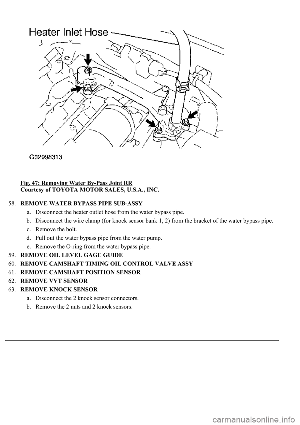
Fig. 47: Removing Water By-Pass Joint RR
Courtesy of TOYOTA MOTOR SALES, U.S.A., INC.
58.REMOVE WATER BYPASS PIPE SUB-ASSY
a. Disconnect the heater outlet hose from the water bypass pipe.
b. Disconnect the wire clamp (for knock sensor bank 1, 2) from the bracket of the water bypass pipe.
c. Remove the bolt.
d. Pull out the water bypass pipe from the water pump.
e. Remove the O-ring from the water bypass pipe.
59.REMOVE OIL LEVEL GAGE GUIDE
60.REMOVE CAMSHAFT TIMING OIL CONTROL VALVE ASSY
61.REMOVE CAMSHAFT POSITION SENSOR
62.REMOVE VVT SENSOR
63.REMOVE KNOCK SENSOR
a. Disconnect the 2 knock sensor connectors.
b. Remove the 2 nuts and 2 knock sensors.
Page 3340 of 4500
b. Apply soapy water to the O-ring.
c. Push in the water bypass pipe end into the pipe hole of the water pump.
d. Install the water bypass pipe with the bolt.
Torque: 18 N.m (184 kgf.cm, 13 ft.lbf)
e. Install the wire clamp to the bracket of the water bypass pipe.
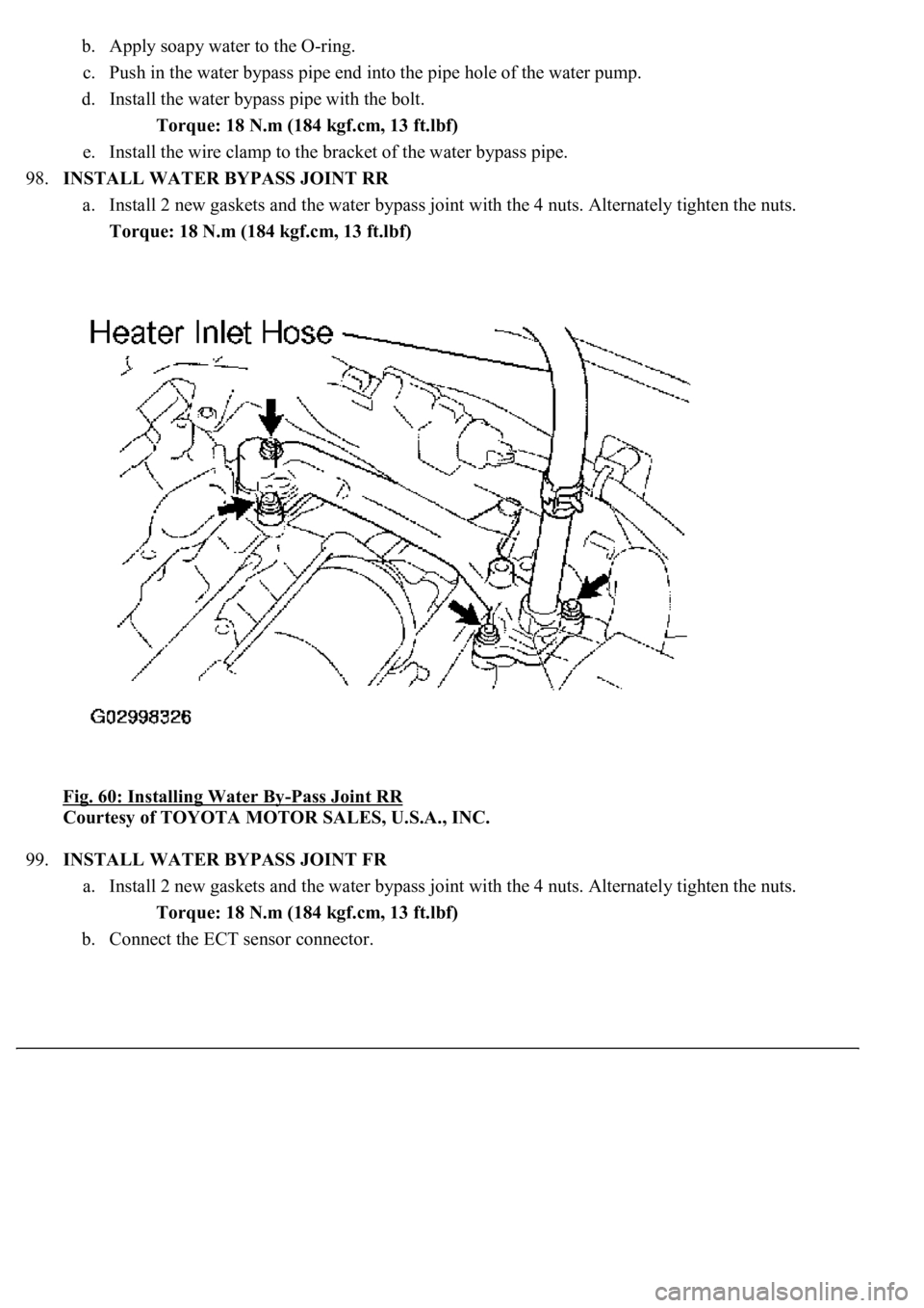
98.INSTALL WATER BYPASS JOINT RR
a. Install 2 new gaskets and the water bypass joint with the 4 nuts. Alternately tighten the nuts.
Torque: 18 N.m (184 kgf.cm, 13 ft.lbf)
Fig. 60: Installing Water By
-Pass Joint RR
Courtesy of TOYOTA MOTOR SALES, U.S.A., INC.
99.INSTALL WATER BYPASS JOINT FR
a. Install 2 new gaskets and the water bypass joint with the 4 nuts. Alternately tighten the nuts.
Torque: 18 N.m (184 kgf.cm, 13 ft.lbf)
b. Connect the ECT sensor connector.
Page 3360 of 4500
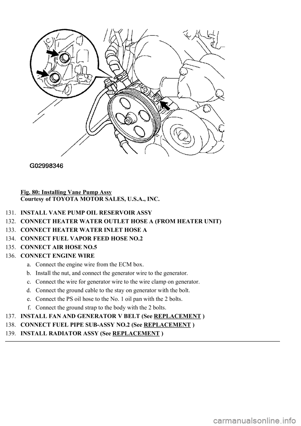
Fig. 80: Installing Vane Pump Assy
Courtesy of TOYOTA MOTOR SALES, U.S.A., INC.
131.INSTALL VANE PUMP OIL RESERVOIR ASSY
132.CONNECT HEATER WATER OUTLET HOSE A (FROM HEATER UNIT)
133.CONNECT HEATER WATER INLET HOSE A
134.CONNECT FUEL VAPOR FEED HOSE NO.2
135.CONNECT AIR HOSE NO.5
136.CONNECT ENGINE WIRE
a. Connect the engine wire from the ECM box.
b. Install the nut, and connect the generator wire to the generator.
c. Connect the wire for generator wire to the wire clamp on generator.
d. Connect the ground cable to the stay on generator with the bolt.
e. Connect the PS oil hose to the No. 1 oil pan with the 2 bolts.
f. Connect the ground strap to the body with the 2 bolts.
137.INSTALL FAN AND GENERATOR V BELT (See REPLACEMENT
)
138.CONNECT FUEL PIPE SUB-ASSY NO.2 (See REPLACEMENT
)
139.INSTALL RADIATOR ASSY (See REPLACEMENT
)
Page 3372 of 4500
Fig. 91: Checking Timing Belt
Courtesy of TOYOTA MOTOR SALES, U.S.A., INC.
c. If there is noticeable wear or cracks on the belt face, check to see if there are nicks on the side of
the idler pulley lock and water pump.
d. If there is wear or damage on only one side of the belt, check the belt guide and the alignment of
each pulley.
e. If there is noticeable wear on the belt teeth, check the timing cover for damage, check that the
gasket has been installed correctly, and check for foreign material on the pulley teeth.
If necessary, replace the timing belt.
17.INSPECT TIMING BELT TENSIONER
a. Visually check the seal portion of the tensioner for oil leakage.
HINT:
If there is only the faint trace of oil on the push rod, the tensioner does not need to be replaced.
If leaka
ge is found, replace the tensioner.
Page 3391 of 4500
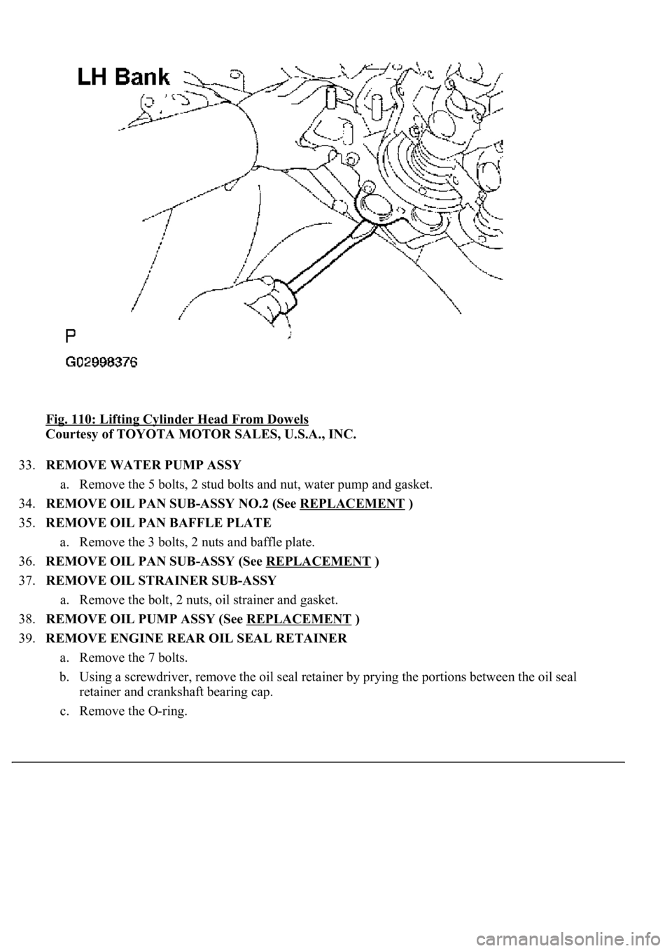
Fig. 110: Lifting Cylinder Head From Dowels
Courtesy of TOYOTA MOTOR SALES, U.S.A., INC.
33.REMOVE WATER PUMP ASSY
a. Remove the 5 bolts, 2 stud bolts and nut, water pump and gasket.
34.REMOVE OIL PAN SUB-ASSY NO.2 (See REPLACEMENT
)
35.REMOVE OIL PAN BAFFLE PLATE
a. Remove the 3 bolts, 2 nuts and baffle plate.
36.REMOVE OIL PAN SUB-ASSY (See REPLACEMENT
)
37.REMOVE OIL STRAINER SUB-ASSY
a. Remove the bolt, 2 nuts, oil strainer and gasket.
38.REMOVE OIL PUMP ASSY (See REPLACEMENT
)
39.REMOVE ENGINE REAR OIL SEAL RETAINER
a. Remove the 7 bolts.
b. Using a screwdriver, remove the oil seal retainer by prying the portions between the oil seal
retainer and crankshaft bearing cap.
c. Remove the O-ring.
Page 3416 of 4500
Fig. 135: Identifying Oil Pan Stud Bolt Diameter
Courtesy of TOYOTA MOTOR SALES, U.S.A., INC.
56.INSTALL OIL PAN SUB-ASSY (See REPLACEMENT
)
57.INSTALL OIL PAN BAFFLE PLATE (See REPLACEMENT
)
58.INSTALL OIL PAN SUB-ASSY NO.2 (See REPLACEMENT
)
59.INSTALL WATER PUMP ASSY
a. Install a new gasket and water pump with the 5 bolts, 2 stud bolts and nut. Uniformly tighten the
bolts, stud bolts and nut in several passes.
Torque:
21 N.m (214 kgf.cm, 16 ft.lbf) for bolt
18 N.m (184 kgf.cm, 13 ft.lbf) for stud bolt and nut
HINT:
Use bolts that are 30 mm (1.18 in.) in len
gth.
Page 3417 of 4500
Fig. 136: Identifying Water Pump Assy Bolts
Courtesy of TOYOTA MOTOR SALES, U.S.A., INC.
60.INSTALL CYLINDER HEAD SUB-ASSY
a. Place a new cylinder head gasket on the cylinder block.
HINT:
The rear side of the cylinder head gasket has marks so that the RH and LH banks can be
distinguished. A "3R" mark is on the RH bank's gasket.
b. Place the cylinder head on the cylinder head gasket.
Page 3453 of 4500
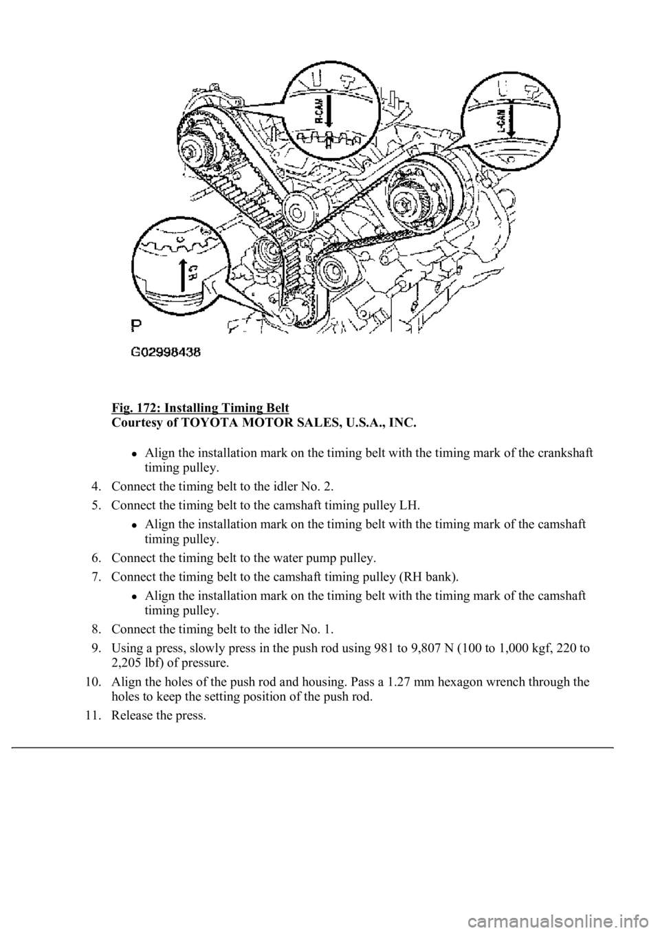
Fig. 172: Installing Timing Belt
Courtesy of TOYOTA MOTOR SALES, U.S.A., INC.
Align the installation mark on the timing belt with the timing mark of the crankshaft
timing pulley.
4. Connect the timing belt to the idler No. 2.
5. Connect the timing belt to the camshaft timing pulley LH.
Align the installation mark on the timing belt with the timing mark of the camshaft
timing pulley.
6. Connect the timing belt to the water pump pulley.
7. Connect the timing belt to the camshaft timing pulley (RH bank).
Align the installation mark on the timing belt with the timing mark of the camshaft
timing pulley.
8. Connect the timing belt to the idler No. 1.
9. Using a press, slowly press in the push rod using 981 to 9,807 N (100 to 1,000 kgf, 220 to
2,205 lbf) of pressure.
10. Align the holes of the push rod and housing. Pass a 1.27 mm hexagon wrench through the
<004b0052004f004800560003005700520003004e00480048005300030057004b004800030056004800570057004c0051004a0003005300520056004c0057004c0052005100030052004900030057004b00480003005300580056004b000300550052004700
1100030003[
11. Release the press.
Page 3478 of 4500
Fig. 195: Turning Camshaft Timing Pulley (RH Bank) Using SST
Courtesy of TOYOTA MOTOR SALES, U.S.A., INC.
e. Disconnect the belt from the timing belt idler No. 1, and remove the belt.
26.INSTALL TIMING BELT
a. Check the belt idler No. 1 and No. 2.
1. Visually check the seal portion of the idler pulley for oil leakage.
If leakage is found, replace the idler.
2. Check that the idler turns smoothly.
If necessary, replace the idler.
b. Check the water pump.
1. Visually check the air hole and water hole for coolant leakage.
If leakage is found, replace the water pump and belt.
2. Turn the pulle
y, and check that the water pump bearing moves smoothly and quietly.