LEXUS LS430 2003 Factory Repair Manual
LS430 2003
LEXUS
LEXUS
https://www.carmanualsonline.info/img/36/57050/w960_57050-0.png
LEXUS LS430 2003 Factory Repair Manual
Page 4116 of 4500
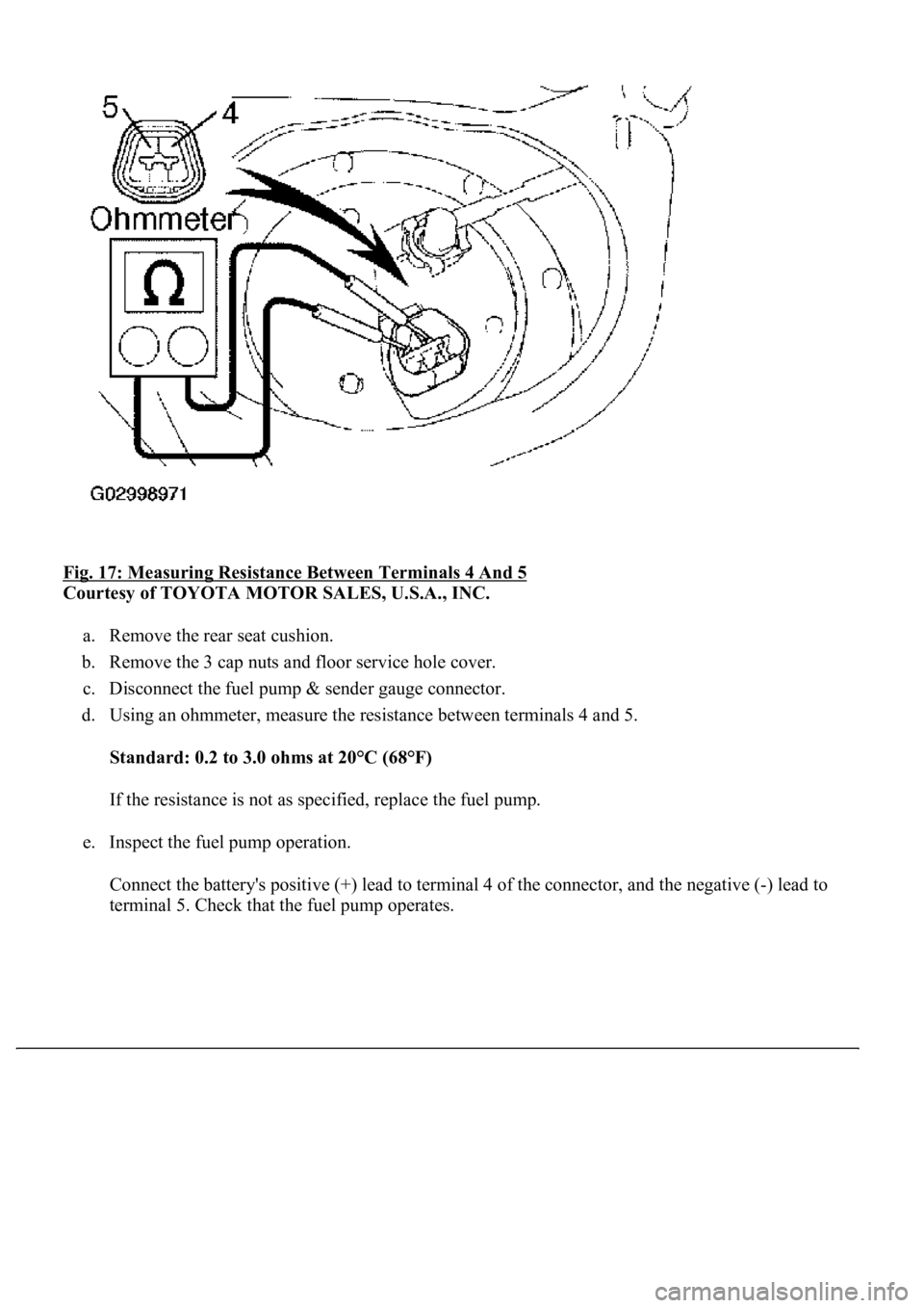
<0029004c004a001100030014001a001d0003003000480044005600580055004c0051004a0003003500480056004c0056005700440051004600480003002500480057005a00480048005100030037004800550050004c00510044004f005600030017000300
240051004700030018[
Courtesy of TOYOTA MOTOR SALES, U.S.A., INC.
a. Remove the rear seat cushion.
b. Remove the 3 cap nuts and floor service hole cover.
c. Disconnect the fuel pump & sender gauge connector.
d. Using an ohmmeter, measure the resistance between terminals 4 and 5.
Standard: 0.2 to 3.0 ohms at 20°C (68°F)
If the resistance is not as specified, replace the fuel pump.
e. Inspect the fuel pump operation.
Connect the battery's positive (+) lead to terminal 4 of the connector, and the negative (-) lead to
terminal 5. Check that the fuel pump operates.
Page 4120 of 4500
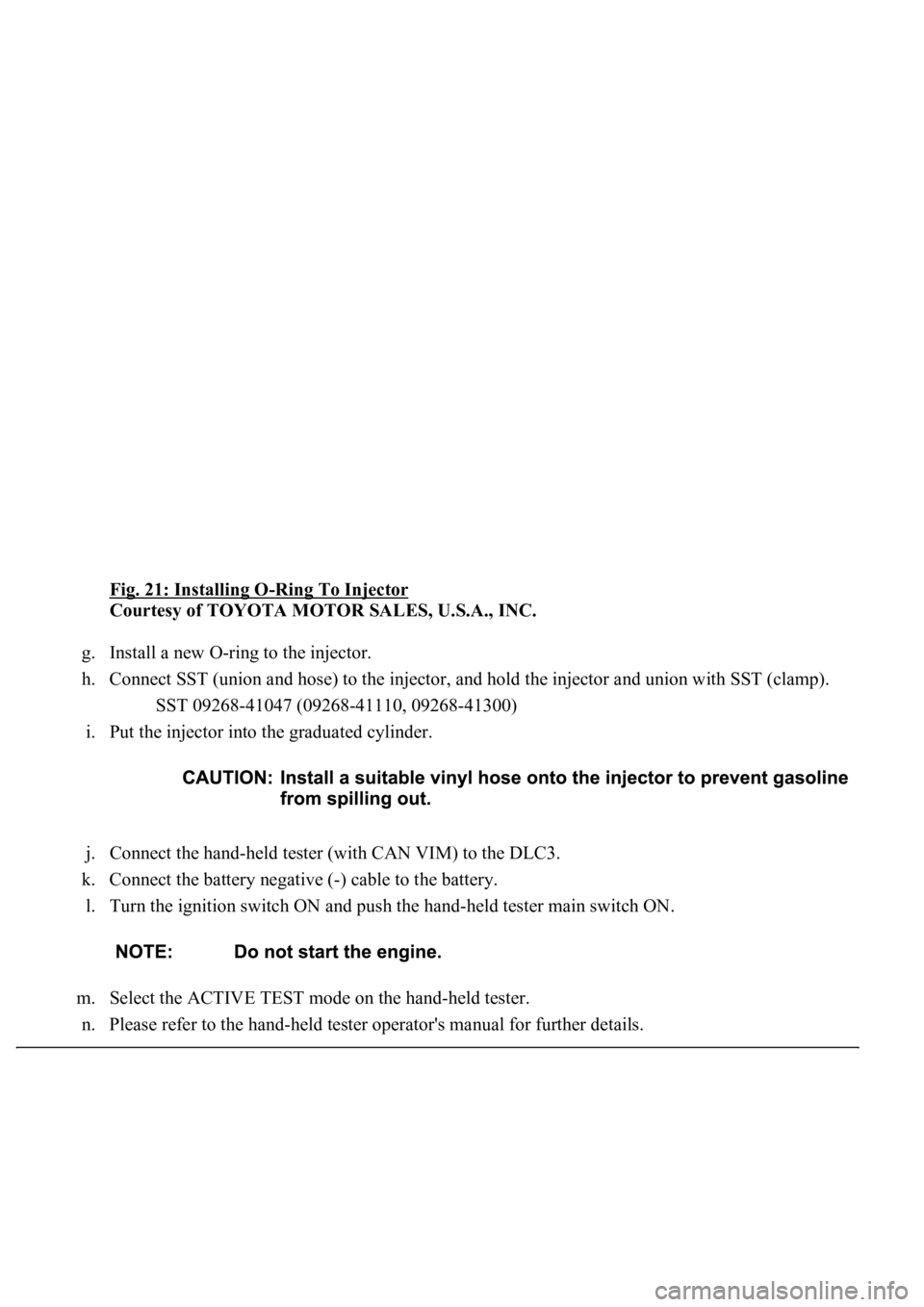
Fig. 21: Installing O-Ring To Injector
Courtesy of TOYOTA MOTOR SALES, U.S.A., INC.
g. Install a new O-ring to the injector.
h. Connect SST (union and hose) to the injector, and hold the injector and union with SST (clamp).
SST 09268-41047 (09268-41110, 09268-41300)
i. Put the injector into the graduated cylinder.
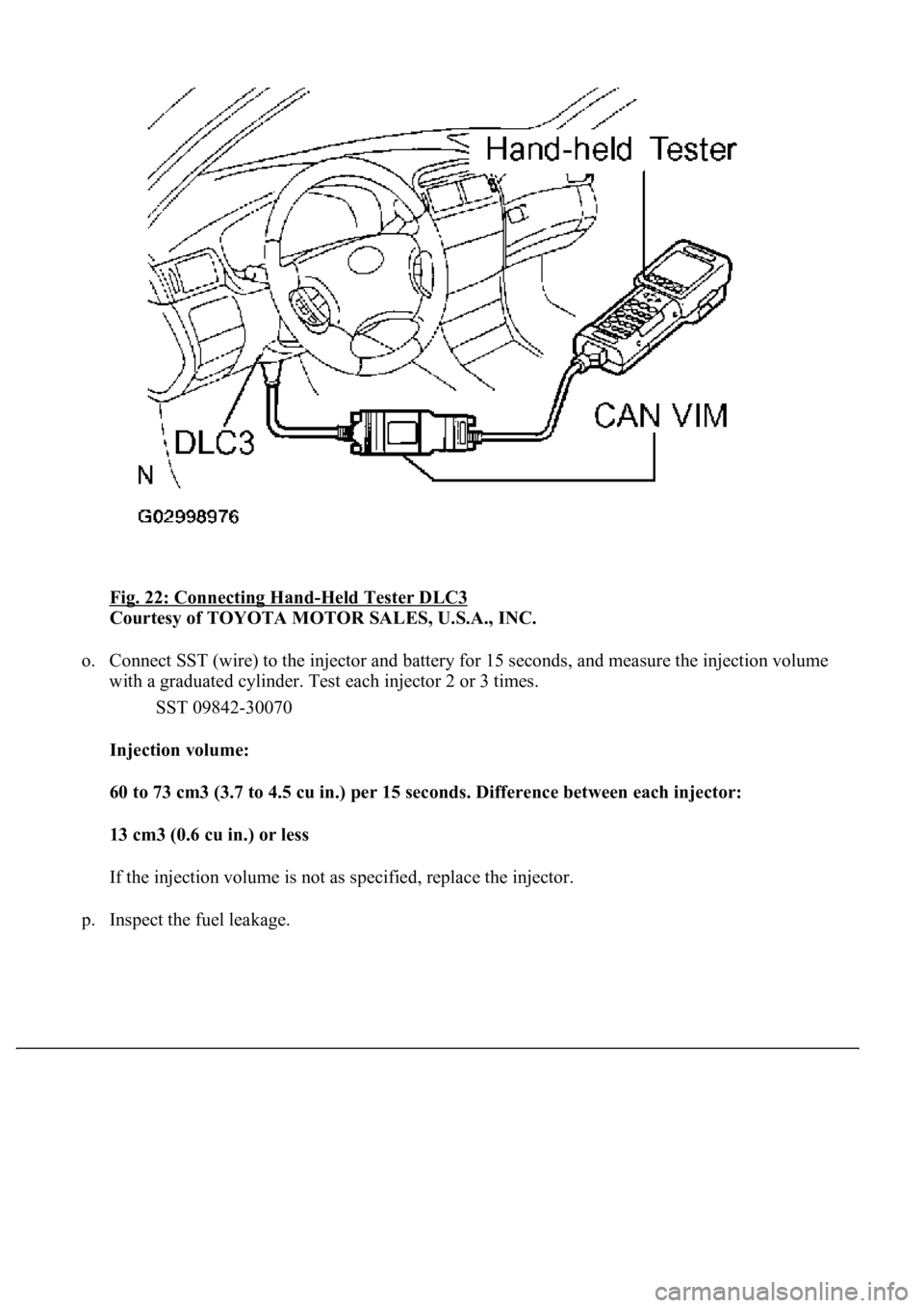
j. Connect the hand-held tester (with CAN VIM) to the DLC3.
k. Connect the battery negative (-) cable to the battery.
l. Turn the ignition switch ON and push the hand-held tester main switch ON.
m. Select the ACTIVE TEST mode on the hand-held tester.
n. Please refer to the han
d-held tester operator's manual for further details.
Page 4121 of 4500
Fig. 22: Connecting Hand-Held Tester DLC3
Courtesy of TOYOTA MOTOR SALES, U.S.A., INC.
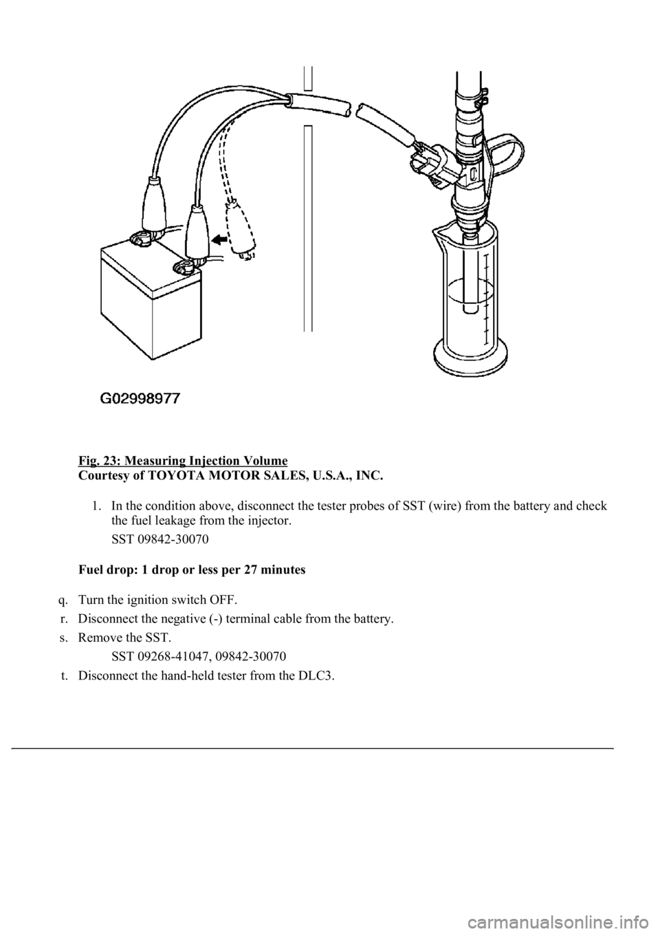
o. Connect SST (wire) to the injector and battery for 15 seconds, and measure the injection volume
with a graduated cylinder. Test each injector 2 or 3 times.
SST 09842-30070
Injection volume:
60 to 73 cm3 (3.7 to 4.5 cu in.) per 15 seconds. Difference between each injector:
13 cm3 (0.6 cu in.) or less
If the injection volume is not as specified, replace the injector.
p. Inspect the fuel leaka
ge.
Page 4122 of 4500
Fig. 23: Measuring Injection Volume
Courtesy of TOYOTA MOTOR SALES, U.S.A., INC.
1. In the condition above, disconnect the tester probes of SST (wire) from the battery and check
the fuel leakage from the injector.
SST 09842-30070
Fuel drop: 1 drop or less per 27 minutes
q. Turn the ignition switch OFF.
r. Disconnect the negative (-) terminal cable from the battery.
s. Remove the SST.
SST 09268-41047, 09842-30070
t. Disconnect the han
d-held tester from the DLC3.
Page 4124 of 4500
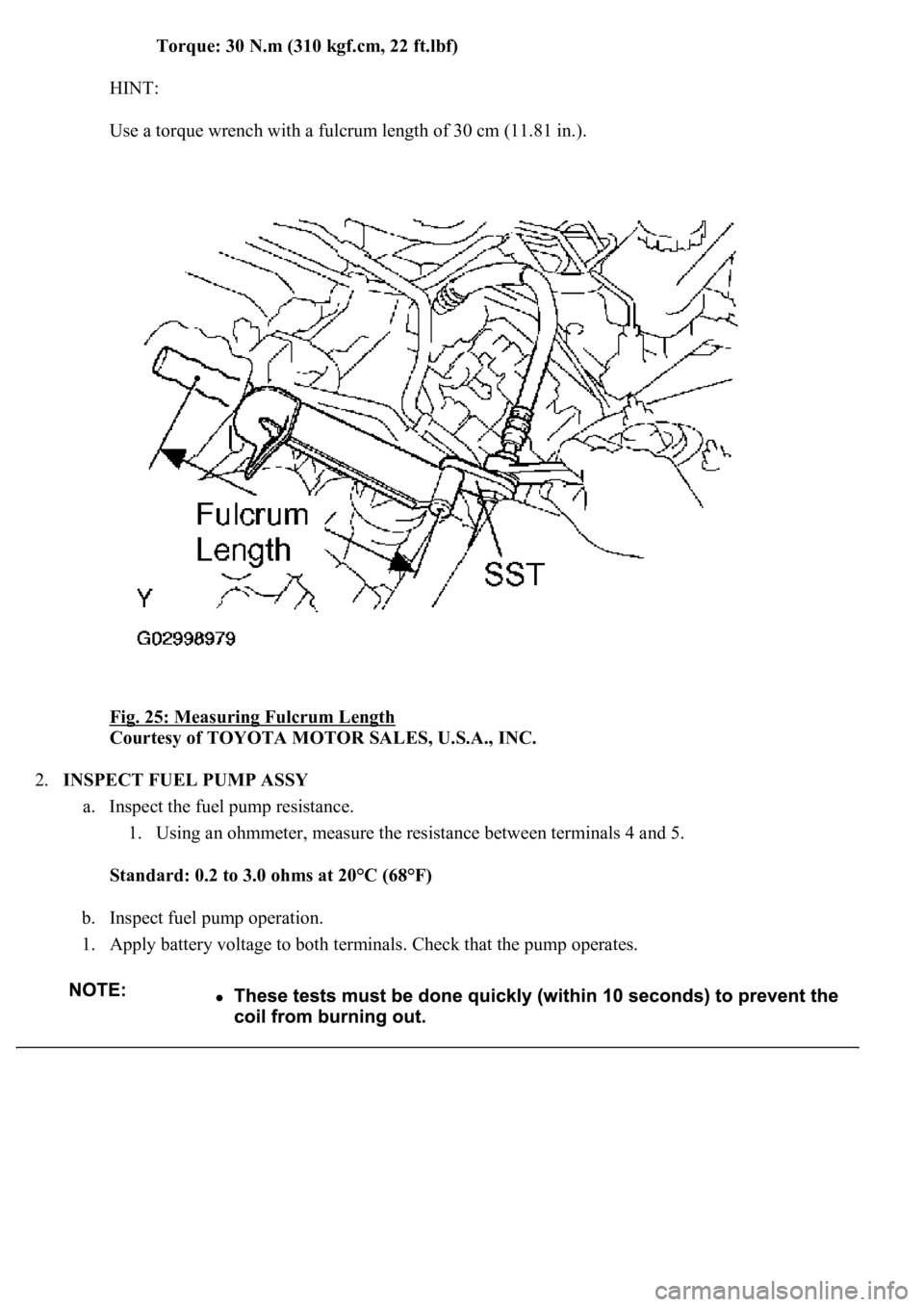
Torque: 30 N.m (310 kgf.cm, 22 ft.lbf)
HINT:
Use a torque wrench with a fulcrum length of 30 cm (11.81 in.).
Fig. 25: Measuring Fulcrum Length
Courtesy of TOYOTA MOTOR SALES, U.S.A., INC.
2.INSPECT FUEL PUMP ASSY
a. Inspect the fuel pump resistance.
1. Using an ohmmeter, measure the resistance between terminals 4 and 5.
Standard: 0.2 to 3.0 ohms at 20°C (68°F)
b. Inspect fuel pump operation.
1. Apply battery voltage to both terminals. Check that the pump operates.
Page 4129 of 4500
REPLACEMENT
1.WORK FOR PREVENTING GASOLINE FROM SPILLING OUT (See PRECAUTION
)
2.DISCONNECT BATTERY NEGATIVE TERMINAL
3.REMOVE V-BANK COVER
a. Remove the 2 nuts and V-bank cover.
4.REMOVE AIR CLEANER INLET NO.1
5.REMOVE INTAKE AIR CONNECTOR PIPE
a. Disconnect the air hose and ventilation hose No. 1.
b. Loosen the hose clamp.
c. Remove the bolt and intake air connector pipe.
6.REMOVE V-BANK COVER BRACKET NO.1
7.REMOVE V-BANK COVER BRACKET NO.2
8.REMOVE V-BANK COVER BRACKET NO.3
9.REMOVE V-VANK COVER BRACKET NO.4
10.REMOVE VACUUM SWITCHING VALVE ASSY
11.DISCONNECT ENGINE WIRE
Page 4134 of 4500
a. Install the intake air connector pipe with the bolt and hose clamp.
Torque:
4.0 N.m (40 kgf.cm, 35 in..lbf) for hose clamp
5.0 N.m (50 kgf.cm, 44 in..lbf) for bolt
b. Connect the air hose and ventilation hose No. 1 together.
27.INSTALL AIR CLEANER INLET NO.1
28.INSPECT FOR FUEL LEAKS (See ON
-VEHICLE INSPECTION )
29.INSTALL V-BANK COVER
Torque: 5.0 N.m (51 kgf.cm, 44 in..lbf)
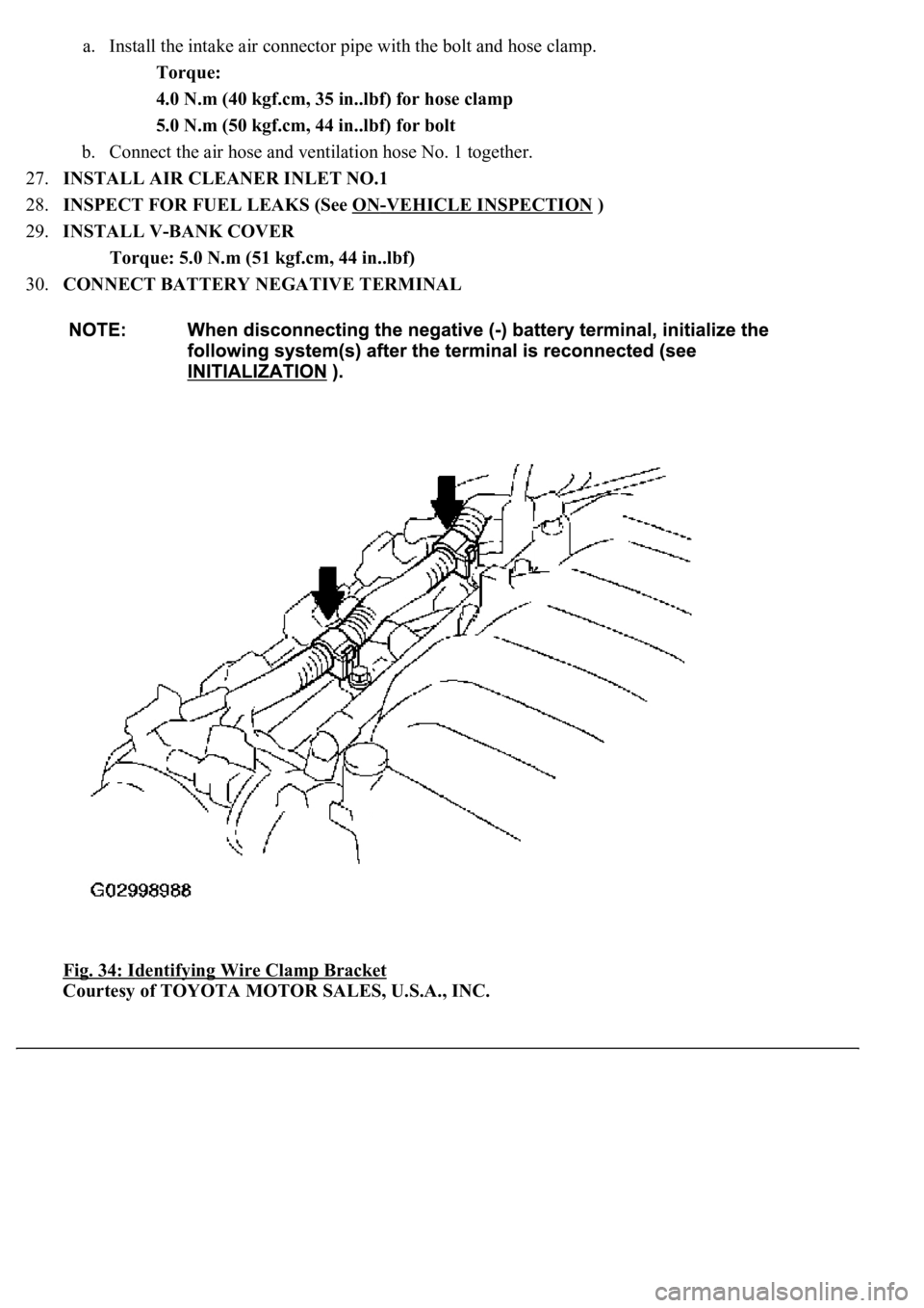
30.CONNECT BATTERY NEGATIVE TERMINAL
Fig. 34: Identifying Wire Clamp Bracket
Courtesy of TOYOTA MOTOR SALES, U.S.A., INC.
Page 4137 of 4500
REPLACEMENT
1.WORK FOR PREVENTING GASOLINE FROM SPILLING OUT (See PRECAUTION
)
2.DISCONNECT BATTERY NEGATIVE TERMINAL
3.DRAIN FUEL (See PRECAUTION
)
4.REMOVE SEPARATE TYPE REAR SEAT CUSHION ASSY LH (SEPARATED TYPE REAR
SEAT) (See OVERHAUL
)
5.REMOVE BENCH TYPE REAR SEAT CUSHION ASSY (FIXED TYPE REAR SEAT) (See
OVERHAUL
)
6.REMOVE REAR FLOOR SERVICE HOLE COVER NO.2
a. Remove the 3 cap nuts and service hole cover.
7.REMOVE FUEL TANK MAIN TUBE SUB-ASSY
Page 4149 of 4500
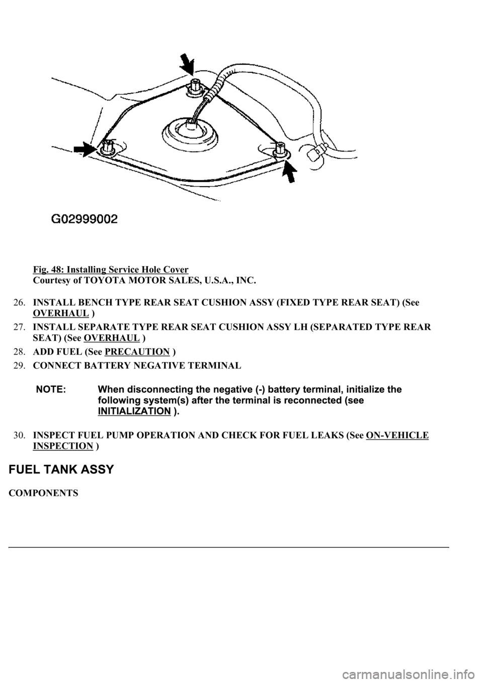
Fig. 48: Installing Service Hole Cover
Courtesy of TOYOTA MOTOR SALES, U.S.A., INC.
26.INSTALL BENCH TYPE REAR SEAT CUSHION ASSY (FIXED TYPE REAR SEAT) (See
OVERHAUL
)
27.INSTALL SEPARATE TYPE REAR SEAT CUSHION ASSY LH (SEPARATED TYPE REAR
SEAT) (See OVERHAUL
)
28.ADD FUEL (See PRECAUTION
)
29.CONNECT BATTERY NEGATIVE TERMINAL
30.INSPECT FUEL PUMP OPERATION AND CHECK FOR FUEL LEAKS (See ON
-VEHICLE
INSPECTION )
COMPONENTS
Page 4151 of 4500
1.WORK FOR PREVENTING GASOLINE FROM SPILLING OUT (See PRECAUTION )
2.DISCONNECT BATTERY NEGATIVE TERMINAL
3.DRAIN FUEL (See PRECAUTION
)
4.REMOVE SEPARATE TYPE REAR SEAT CUSHION ASSY LH (SEPARATED TYPE REAR
SEAT) (See OVERHAUL
)
5.REMOVE BENCH TYPE REAR SEAT CUSHION ASSY (FIXED TYPE REAR SEAT) (See
OVERHAUL
)
6.REMOVE REAR FLOOR SERVICE HOLE COVER NO.2 (See REPLACEMENT
)
7.REMOVE FUEL TANK MAIN TUBE SUB-ASSY
a. Disconnect the connector in the fuel tank side.
1. Remove the tube joint clip.
2. Pull out the fuel main tube.
3. Plu
g the port of the fuel suction plate with a clean rubber cap.
