LEXUS LS430 2003 Factory Repair Manual
LS430 2003
LEXUS
LEXUS
https://www.carmanualsonline.info/img/36/57050/w960_57050-0.png
LEXUS LS430 2003 Factory Repair Manual
Page 4291 of 4500
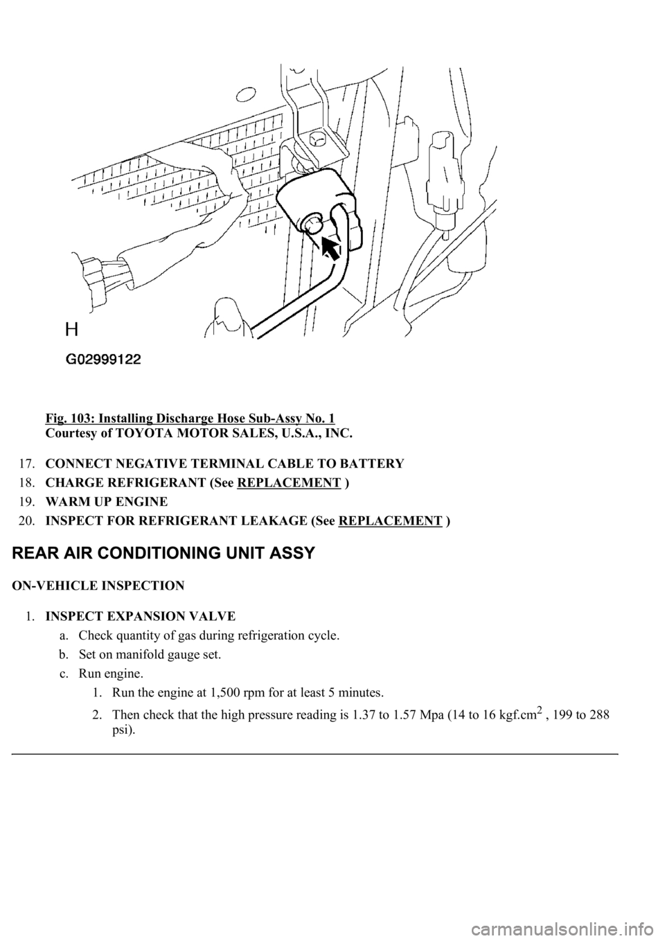
Fig. 103: Installing Discharge Hose Sub-Assy No. 1
Courtesy of TOYOTA MOTOR SALES, U.S.A., INC.
17.CONNECT NEGATIVE TERMINAL CABLE TO BATTERY
18.CHARGE REFRIGERANT (See REPLACEMENT
)
19.WARM UP ENGINE
20.INSPECT FOR REFRIGERANT LEAKAGE (See REPLACEMENT
)
ON-VEHICLE INSPECTION
1.INSPECT EXPANSION VALVE
a. Check quantity of gas during refrigeration cycle.
b. Set on manifold gauge set.
c. Run engine.
1. Run the engine at 1,500 rpm for at least 5 minutes.
2. Then check that the high pressure reading is 1.37 to 1.57 Mpa (14 to 16 kgf.cm
2 , 199 to 288
psi).
Page 4323 of 4500
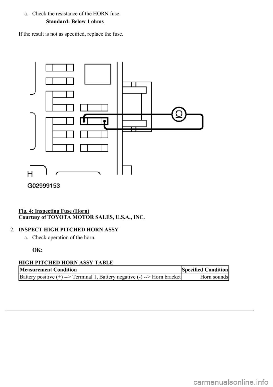
a. Check the resistance of the HORN fuse.
Standard: Below 1 ohms
If the result is not as specified, replace the fuse.
Fig. 4: Inspecting Fuse (Horn)
Courtesy of TOYOTA MOTOR SALES, U.S.A., INC.
2.INSPECT HIGH PITCHED HORN ASSY
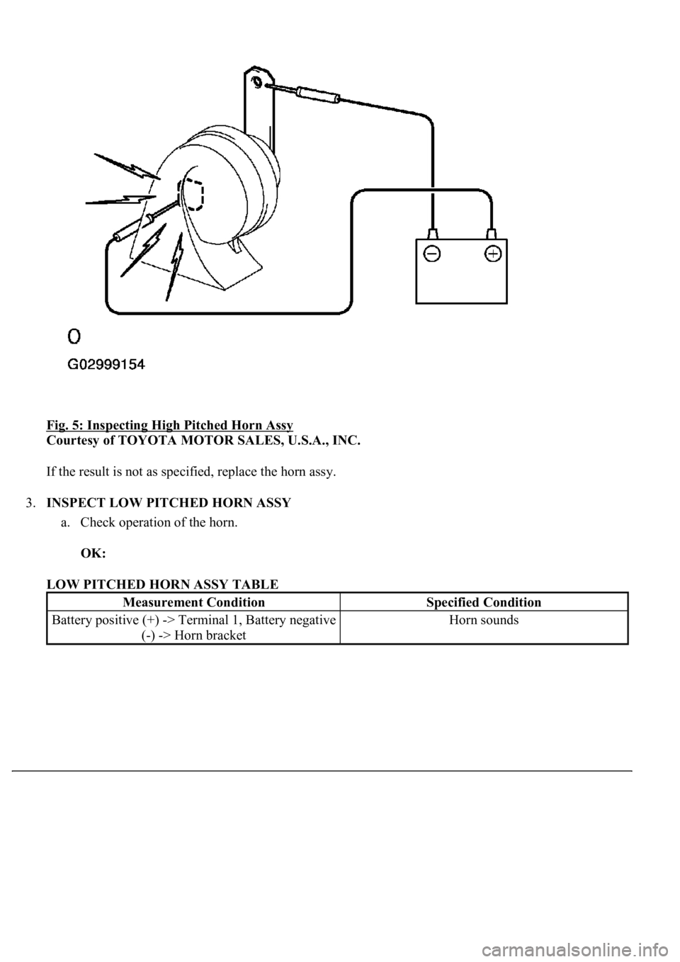
a. Check operation of the horn.
OK:
HIGH PITCHED HORN ASSY TABLE
Measurement ConditionSpecified Condition
Battery positive (+) --> Terminal 1, Battery negative (-) --> Horn bracketHorn sounds
Page 4324 of 4500
Fig. 5: Inspecting High Pitched Horn Assy
Courtesy of TOYOTA MOTOR SALES, U.S.A., INC.
If the result is not as specified, replace the horn assy.
3.INSPECT LOW PITCHED HORN ASSY
a. Check operation of the horn.
OK:
LOW PITCHED HORN ASSY TABLE
Measurement ConditionSpecified Condition
Battery positive (+) -> Terminal 1, Battery negative
(-) -> Horn bracketHorn sounds
Page 4352 of 4500
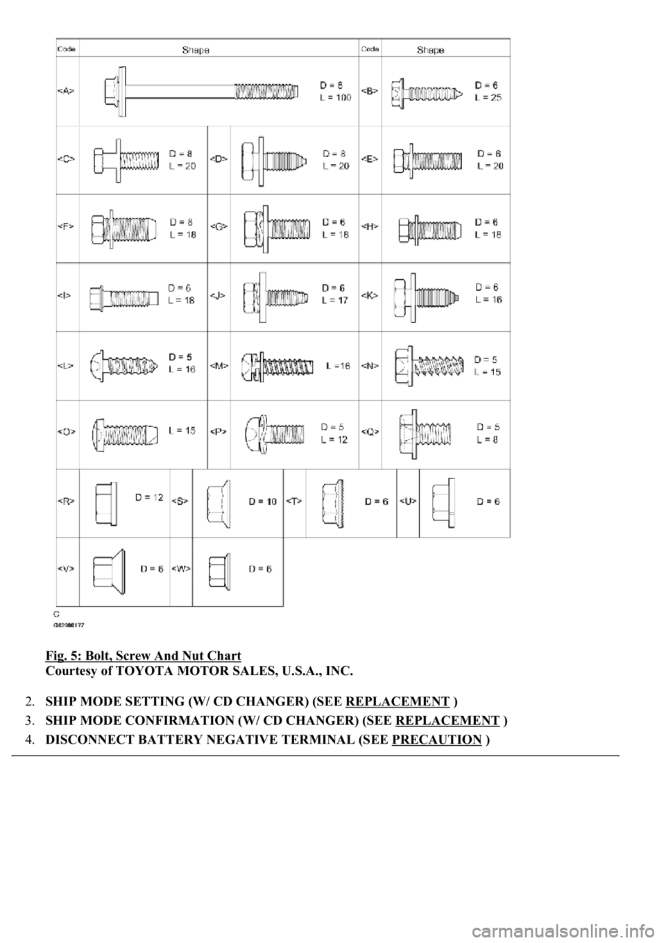
Fig. 5: Bolt, Screw And Nut Chart
Courtesy of TOYOTA MOTOR SALES, U.S.A., INC.
2.SHIP MODE SETTING (W/ CD CHANGER) (SEE REPLACEMENT
)
3.SHIP MODE CONFIRMATION (W/ CD CHANGER) (SEE REPLACEMENT
)
4.DISCONNECT BATTERY NEGATIVE TERMINAL (SEE PRECAUTION
)
Page 4353 of 4500
HINT:
Disconnect the battery negative terminal with the steering column assy extended.
Be sure to extend the steering column, otherwise the steering column cover cannot be removed.
5.PLACE FRONT WHEELS FACING STRAIGHT AHEAD
6.REMOVE SWITCH & VOLUME CASE (SEE OVERHAUL
)
7.REMOVE STEERING WHEEL COVER LOWER NO.2 (SEE OVERHAUL
)
8.REMOVE HORN BUTTON ASSY (SEE OVERHAUL
)
9.REMOVE STEERING WHEEL ASSY (SEE OVERHAUL
)
<00360036003700030013001c001c001800130010001800130013001400160003000b0013001c001c00180014001000130018001300140013000f00030013001c001c00180015001000130018001300140013000f00030013001c001c001800160010001300
18001300150013000f00030013001c001c0018001700100013[5021)
10.REMOVE STEERING COLUMN COVER (SEE OVERHAUL
)
11.REMOVE SPIRAL CABLE SUB-ASSY (SEE REPLACEMENT
)
12.REMOVE TURN SIGNAL SWITCH ASSY (SEE REPLACEMENT
)
13.REMOVE INSTRUMENT PANEL SAFETY PAD GARNISH SUB-ASSY
a. Using a screwdriver, disengage the upper/lower 2 claws inside the instrument panel safety pad
garnish sub-assy.
HINT:
Tape up the screwdriver tip before use.
Page 4388 of 4500
Fig. 40: Installing Instrument Panel Air Bag Assy Lower No.1
Courtesy of TOYOTA MOTOR SALES, U.S.A., INC.
73.INSTALL SPIRAL CABLE SUB-ASSY (SEE REPLACEMENT
)
74.CENTER SPIRAL CABLE (SEE REPLACEMENT
)
75.INSTALL STEERING WHEEL ASSY (SEE OVERHAUL
)
76.STEERING WHEEL CENTER POINT
77.INSTALL HORN BUTTON ASSY (SEE OVERHAUL
)
78.CONNECT BATTERY NEGATIVE TERMINAL
79.INSPECT HORN BUTTON ASSY (SEE REPLACEMENT
)
80.INSPECT SRS WARNING LIGHT (SEE DIAGNOSIS SYSTEM
)
81.PERFORM INITIALIZATION (SEE INITIALIZATION
)
OVERHAUL
HINt:
Page 4406 of 4500
VACUUM SWITCHING VALVE ASSY FOR IAC VALVE
If the resistance is not as specified, replace the VSV assy.
b. Check the VSV operation.
1. Check that air flows from port E to the filter.
If the result is not as specified, replace the VSV assy.
Fig. 7: Checking Air Flows From Port E To Filter
Courtesy of TOYOTA MOTOR SALES, U.S.A., INC.
2. Apply battery positive voltage across the terminals.
3. Check that air flows from port E to port F.
Tester ConnectionSpecified Condition
1 - 233 to 39 ohms at 20°C (68°F)
1 - Body ground, 2 - Body ground10 kohms or higher
Page 4426 of 4500
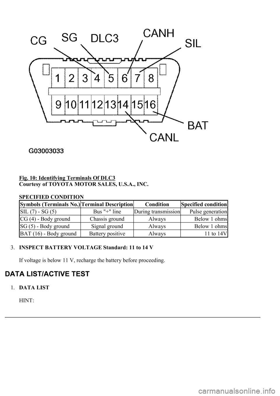
Fig. 10: Identifying Terminals Of DLC3
Courtesy of TOYOTA MOTOR SALES, U.S.A., INC.
SPECIFIED CONDITION
3.INSPECT BATTERY VOLTAGE Standard: 11 to 14 V
If voltage is below 11 V, recharge the battery before proceeding.
1.DATA LIST
HINT:
Symbols (Terminals No.)Terminal DescriptionConditionSpecified condition
SIL (7) - SG (5)Bus "+" lineDuring transmissionPulse generation
CG (4) - Body groundChassis groundAlwaysBelow 1 ohms
SG (5) - Body groundSignal groundAlwaysBelow 1 ohms
BAT (16) - Body groundBattery positiveAlways11 to 14V
Page 4430 of 4500
Standard: Below 1 ohms
NG: REPLACE FUSE
OK: GO TO NEXT STEP
2.INSPECT RELAY (Marking: D-IG1)
a. Remove the D-IG1 relay from the driver side J/B.
b. Measure the resistance.
Standard:
Fig. 15: Identifying terminals Of D
-IG1 Relay
Courtesy of TOYOTA MOTOR SALES, U.S.A., INC.
SPECIFIED CONDITION
NG: REPLACE RELAY
OK: GO TO NEXT STEP
Tester connectionSpecified condition
3 - 510 kohms or higher
3 - 5Below 1 ohms (when battery voltage is applied to terminals 1 and 2)
Page 4431 of 4500
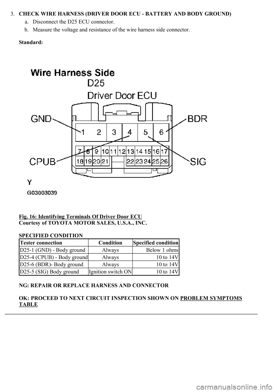
3.CHECK WIRE HARNESS (DRIVER DOOR ECU - BATTERY AND BODY GROUND)
a. Disconnect the D25 ECU connector.
b. Measure the voltage and resistance of the wire harness side connector.
Standard:
Fig. 16: Identifying Terminals Of Driver Door ECU
Courtesy of TOYOTA MOTOR SALES, U.S.A., INC.
SPECIFIED CONDITION
NG: REPAIR OR REPLACE HARNESS AND CONNECTOR
OK: PROCEED TO NEXT CIRCUIT INSPECTION SHOWN ON PROBLEM SYMPTOMS
TABLE
Tester connectionConditionSpecified condition
D25-1 (GND) - Body groundAlwaysBelow 1 ohms
D25-4 (CPUB) - Body groundAlways10 to 14V
D25-6 (BDR)- Body groundAlways10 to 14V
D25-5 (SIG) Body groundIgnition switch ON10 to 14V
