battery LEXUS LS430 2003 Factory Repair Manual
[x] Cancel search | Manufacturer: LEXUS, Model Year: 2003, Model line: LS430, Model: LEXUS LS430 2003Pages: 4500, PDF Size: 87.45 MB
Page 3990 of 4500
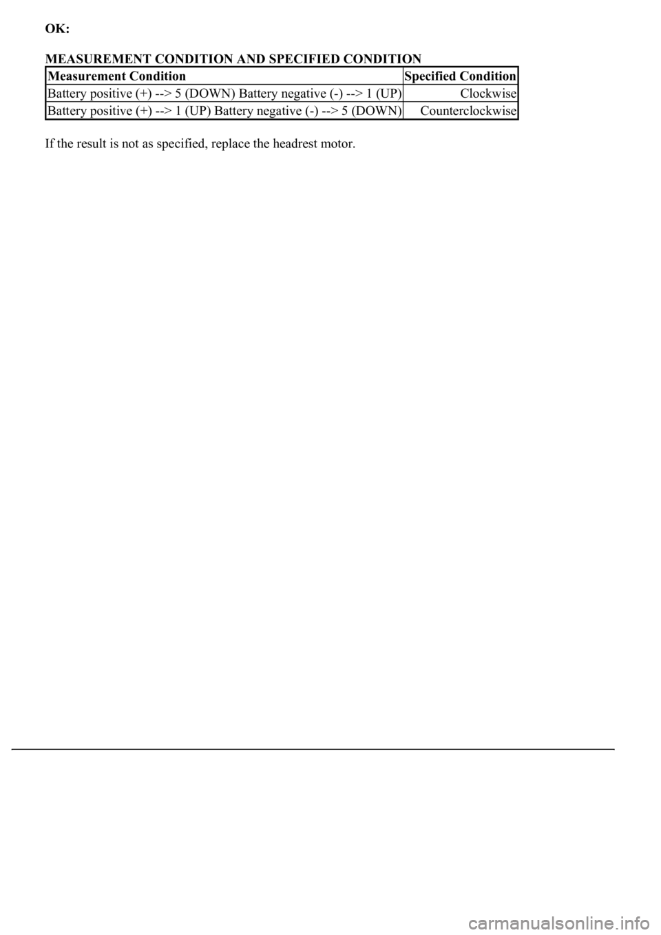
OK:
MEASUREMENT CONDITION AND SPECIFIED CONDITION
If the result is not as specified, replace the headrest motor.
Measurement ConditionSpecified Condition
Battery positive (+) --> 5 (DOWN) Battery negative (-) --> 1 (UP)Clockwise
Battery positive (+) --> 1 (UP) Battery negative (-) --> 5 (DOWN)Counterclockwise
Page 4082 of 4500
3.INSPECT BATTERY VOLTAGE
Standard: 11 to 14 V
If voltage is below 11 V, recharge the battery before proceeding.
1.DATA LIST
HINT:
Using the hand-held tester's DATA LIST allows switch, sensor, actuator and other item values to be read
without removing any parts. Reading the DATA LIST early in troubleshooting is one way to save time.
a. Connect the hand-held tester (with CAN VIM) to the DLC3.
b. Turn the ignition switch ON.
c. Read the DATA LIST on the tester's screen.
Driver side J/B ECU:
DRIVER SIDE J/B ECU
2.ACTIVE TEST
HINT:
Performing the hand-held tester's ACTIVE TEST allows relay, VSV, actuator and other items to be
operated without removing any parts. Performing the ACTIVE TEST early in troubleshooting is one way
to save time. The DATA LIST can be displayed during the ACTIVE TEST.
a. Connect the hand-held tester (with CAN VIM) to the DLC3.
b. Turn the ignition switch ON.
c. Perform the ACTIVE TEST accordin
g to the display on the tester.
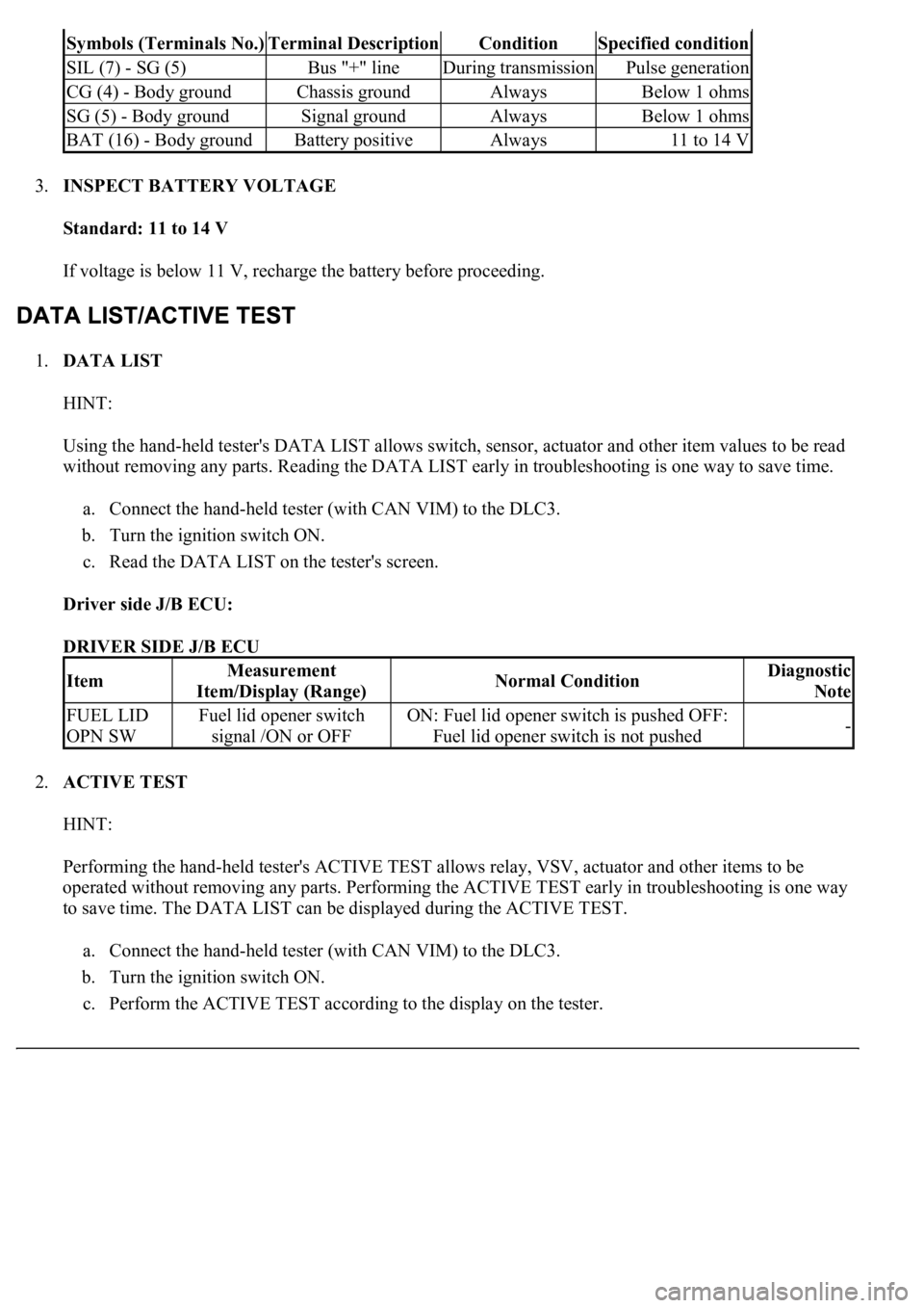
Symbols (Terminals No.)Terminal DescriptionConditionSpecified condition
SIL (7) - SG (5)Bus "+" lineDuring transmissionPulse generation
CG (4) - Body groundChassis groundAlwaysBelow 1 ohms
SG (5) - Body groundSignal groundAlwaysBelow 1 ohms
BAT (16) - Body groundBattery positiveAlways11 to 14 V
ItemMeasurement
Item/Display (Range)Normal ConditionDiagnostic
Note
FUEL LID
OPN SWFuel lid opener switch
signal /ON or OFFON: Fuel lid opener switch is pushed OFF:
Fuel lid opener switch is not pushed-
Page 4085 of 4500
INSPECTION PROCEDURE
1.INSPECT FUSE (MPX-B3, MPX-IG and AM1, D/C CUT)
a. Remove the MPX-B3 fuse from the passenger side J/B.
b. Remove the MPX-IG and AM1 fuse from the driver side J/B.
c. Remove the D/C CUT fuse from the FL block assy.
d. Measure the resistance.
Standard: Below 1 ohms
NG: REPLACE FUSE
OK: GO TO NEXT STEP
2.CHECK WIRE HARNESS (LUGGAGE ROOM J/B ECU - BATTERY AND BODY GROUND)
a. Disconnect the LA, LF and LL J/B, and L14 ECU connectors.
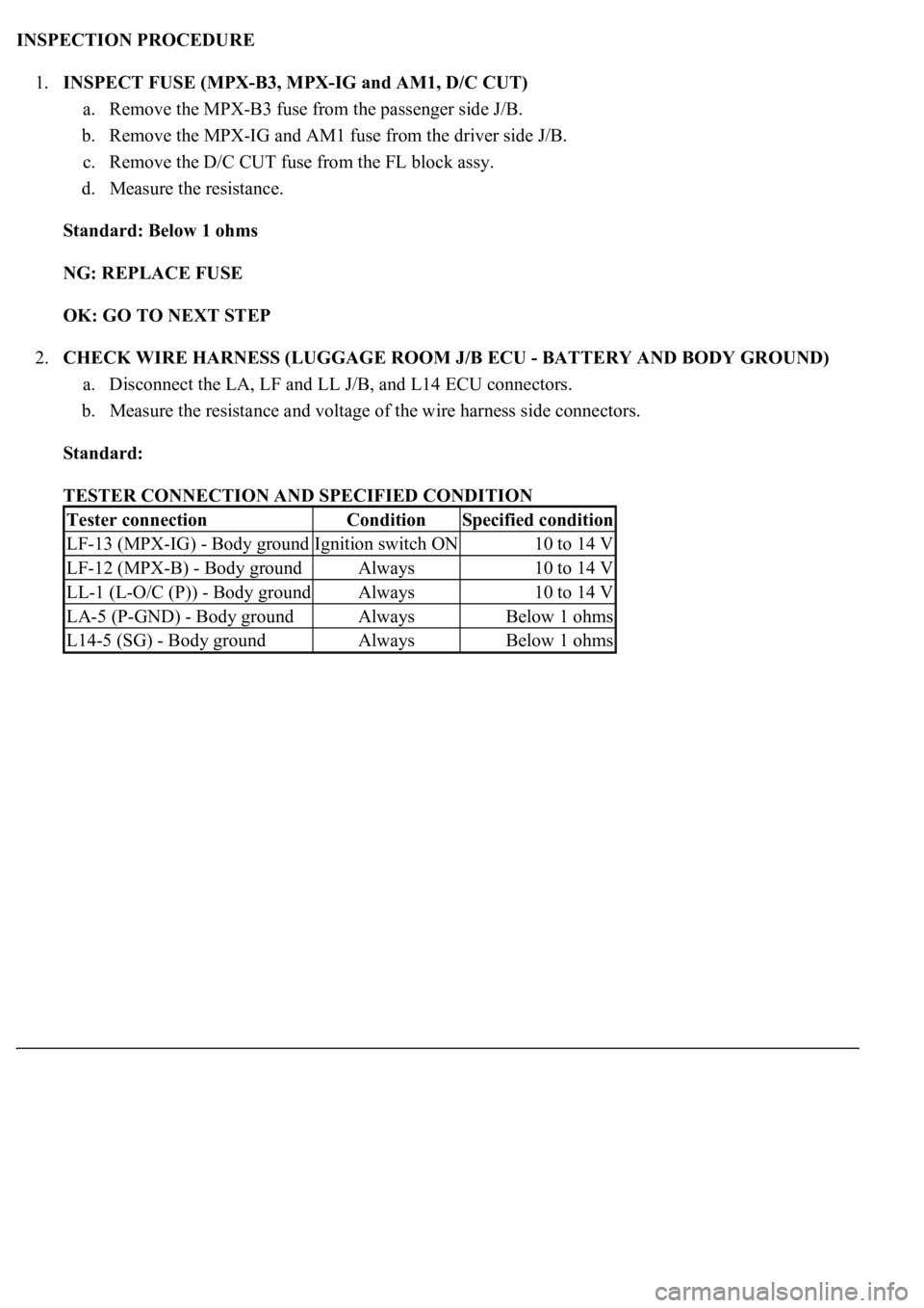
b. Measure the resistance and voltage of the wire harness side connectors.
Standard:
TESTER CONNECTION AND SPECIFIED CONDITION
Tester connectionConditionSpecified condition
LF-13 (MPX-IG) - Body groundIgnition switch ON10 to 14 V
LF-12 (MPX-B) - Body groundAlways10 to 14 V
LL-1 (L-O/C (P)) - Body groundAlways10 to 14 V
LA-5 (P-GND) - Body groundAlwaysBelow 1 ohms
L14-5 (SG) - Body groundAlwaysBelow 1 ohms
Page 4093 of 4500
OK: Fuel lid opener is opened.
NG: Go to step 2
OK: PROCEED TO NEXT CIRCUIT INSPECTION SHOWN ON PROBLEM SYMPTOMS
TABLE
2.INSPECT FUSE (FUEL OPN)
a. Remove the FUEL OPN fuse from the luggage room J/B.
b. Measure the resistance.
Standard: Below 1 ohms
NG: REPLACE FUSE
OK: GO TO NEXT STEP
3.INSPECT FUEL LID OPENER MOTOR ASSY
a. Apply battery voltage to the motor and check operation of the fuel lid opener motor.
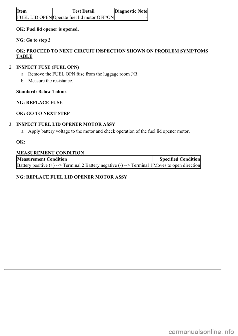
OK:
MEASUREMENT CONDITION
NG: REPLACE FUEL LID OPENER MOTOR ASSY
ItemTest DetailDiagnostic Note
FUEL LID OPENOperate fuel lid motor OFF/ON-
Measurement ConditionSpecified Condition
Battery positive (+) --> Terminal 2 Battery negative (-) --> Terminal 1Moves to open direction
Page 4098 of 4500
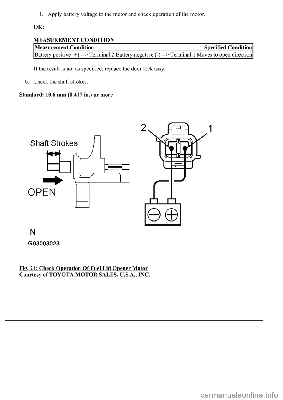
1. Apply battery voltage to the motor and check operation of the motor.
OK:
MEASUREMENT CONDITION
If the result is not as specified, replace the door lock assy.
b. Check the shaft strokes.
Standard: 10.6 mm (0.417 in.) or more
Fig. 21: Check Operation Of Fuel Lid Opener Motor
Courtesy of TOYOTA MOTOR SALES, U.S.A., INC.
Measurement ConditionSpecified Condition
Battery positive (+) --> Terminal 2 Battery negative (-) --> Terminal 1Moves to open direction
Page 4102 of 4500
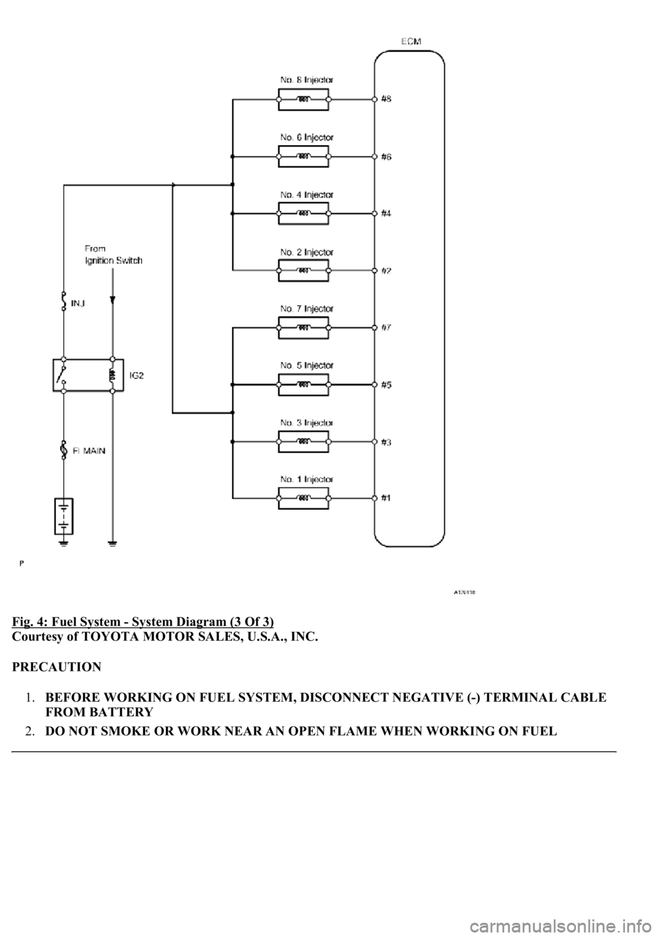
Fig. 4: Fuel System - System Diagram (3 Of 3)
Courtesy of TOYOTA MOTOR SALES, U.S.A., INC.
PRECAUTION
1.BEFORE WORKING ON FUEL SYSTEM, DISCONNECT NEGATIVE (-) TERMINAL CABLE
FROM BATTERY
2.DO NOT SMOKE OR WORK NEAR AN OPEN FLAME WHEN WORKING ON FUEL
Page 4103 of 4500
SYSTEM
3.KEEP GASOLINE AWAY FROM RUBBER AND LEATHER PARTS
4.DISCHARGE FUEL SYSTEM PRESSURE
a. Using the F/PMP relay:
1. Remove the engine room R/B cover upper.
2. Remove the F/PMP relay.
3. Start the engine.
4. After the engine has stopped, turn the ignition switch OFF.
5. Crank the engine. Check that the engine does not start.
6. Remove the fuel tank cap to discharge pressure from the fuel tank.
7. Disconnect the negative (-) battery terminal cable.
8. Reinstall the F/PMP relay.
b. Using the fuel pump connector:
1. Remove the rear seat cushion.
2. Remove the rear floor service hole cover.
3. Disconnect the fuel pump connector.
4. Start the engine.
5. After the engine has stopped, turn the ignition switch OFF.
6. Crank the engine. Check that the engine does not start.
7. Remove the fuel tank cap to discharge pressure from the fuel tank.
8. Disconnect the cable from the negative (-) battery terminal.
9. Reconnect the fuel pump connector.
10. Install the rear floor service hole cover.
11. Install the rear seat.
Page 4113 of 4500
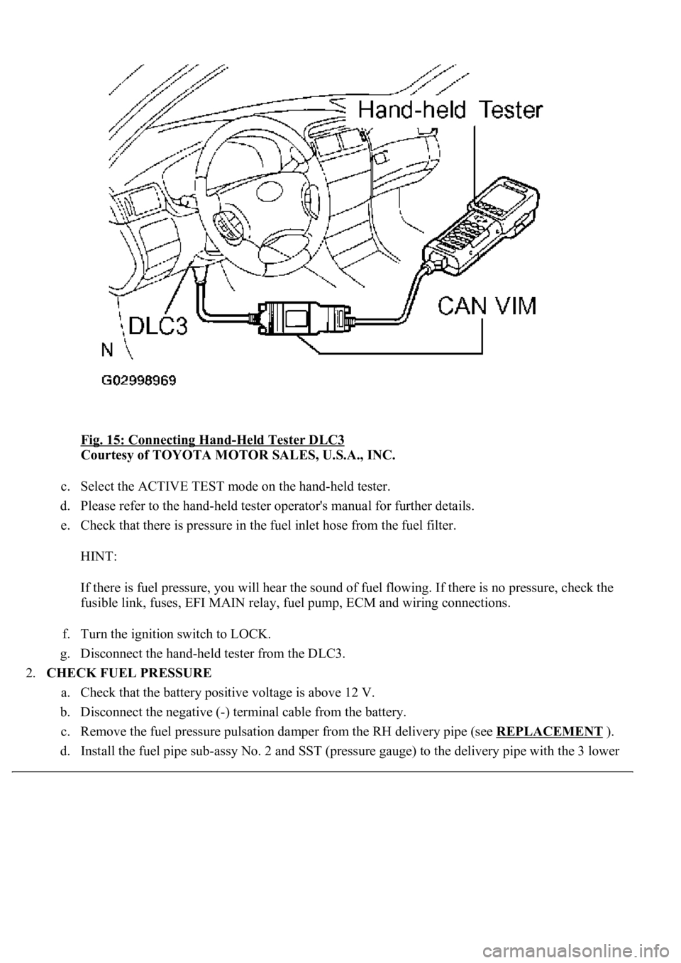
Fig. 15: Connecting Hand-Held Tester DLC3
Courtesy of TOYOTA MOTOR SALES, U.S.A., INC.
c. Select the ACTIVE TEST mode on the hand-held tester.
d. Please refer to the hand-held tester operator's manual for further details.
e. Check that there is pressure in the fuel inlet hose from the fuel filter.
HINT:
If there is fuel pressure, you will hear the sound of fuel flowing. If there is no pressure, check the
fusible link, fuses, EFI MAIN relay, fuel pump, ECM and wiring connections.
f. Turn the ignition switch to LOCK.
g. Disconnect the hand-held tester from the DLC3.
2.CHECK FUEL PRESSURE
a. Check that the battery positive voltage is above 12 V.
b. Disconnect the negative (-) terminal cable from the battery.
c. Remove the fuel pressure pulsation damper from the RH delivery pipe (see REPLACEMENT
).
d. Install the fuel pipe sub-ass
y No. 2 and SST (pressure gauge) to the delivery pipe with the 3 lower
Page 4114 of 4500
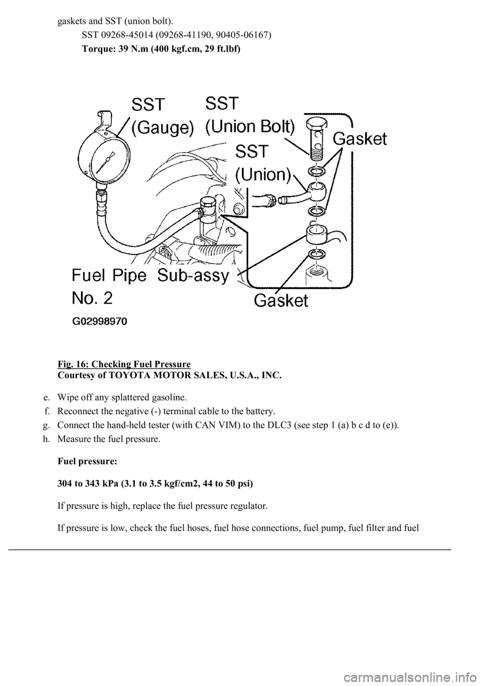
gaskets and SST (union bolt).
SST 09268-45014 (09268-41190, 90405-06167)
Torque: 39 N.m (400 kgf.cm, 29 ft.lbf)
Fig. 16: Checking Fuel Pressure
Courtesy of TOYOTA MOTOR SALES, U.S.A., INC.
e. Wipe off any splattered gasoline.
f. Reconnect the negative (-) terminal cable to the battery.
g. Connect the hand-held tester (with CAN VIM) to the DLC3 (see step 1 (a) b c d to (e)).
h. Measure the fuel pressure.
Fuel pressure:
304 to 343 kPa (3.1 to 3.5 kgf/cm2, 44 to 50 psi)
If pressure is high, replace the fuel pressure regulator.
If pressure is low, check the fuel hoses, fuel hose connections, fuel pump, fuel filter and fuel
Page 4115 of 4500
pressure regulator.
i. Disconnect the hand-held tester from the DLC3.
j. Start the engine.
k. Measure the fuel pressure at idle.
Fuel pressure: 304 to 343 kPa (3.1 to 3.5 kgf/cm2, 44 to 50 psi)
l. Stop the engine.
m. Check that the fuel pressure remains as specified for 5 minutes after the engine has stopped.
Fuel pressure: 147 kPa (1.5 kgf/cm2, 21 psi) or more
If pressure is not as specified, check the fuel pump, pressure regulator and/or injectors.
n. After checking fuel pressure, disconnect the negative (-) terminal cable from the battery and
carefully remove the SST to prevent gasoline from spilling.
SST 09268-45014
o. Reinstall the fuel pressure pulsation damper to the RH delivery pipe (see REPLACEMENT
).
p. Reconnect the negative (-) terminal cable to the battery.
q. Check for fuel leaks.
3.INSPECT FUEL PUMP