On vehicle inspection LEXUS LS430 2003 Factory Owner's Manual
[x] Cancel search | Manufacturer: LEXUS, Model Year: 2003, Model line: LS430, Model: LEXUS LS430 2003Pages: 4500, PDF Size: 87.45 MB
Page 557 of 4500
POWER SOURCE CIRCUIT ) is displayed, carry out the necessary inspection. If they are output at the
same time, carry out the necessary inspection for DTC C1774 first.
NG: REPAIR CIRCUIT INDICATED BY OUTPUT CODE
OK:Go to next step
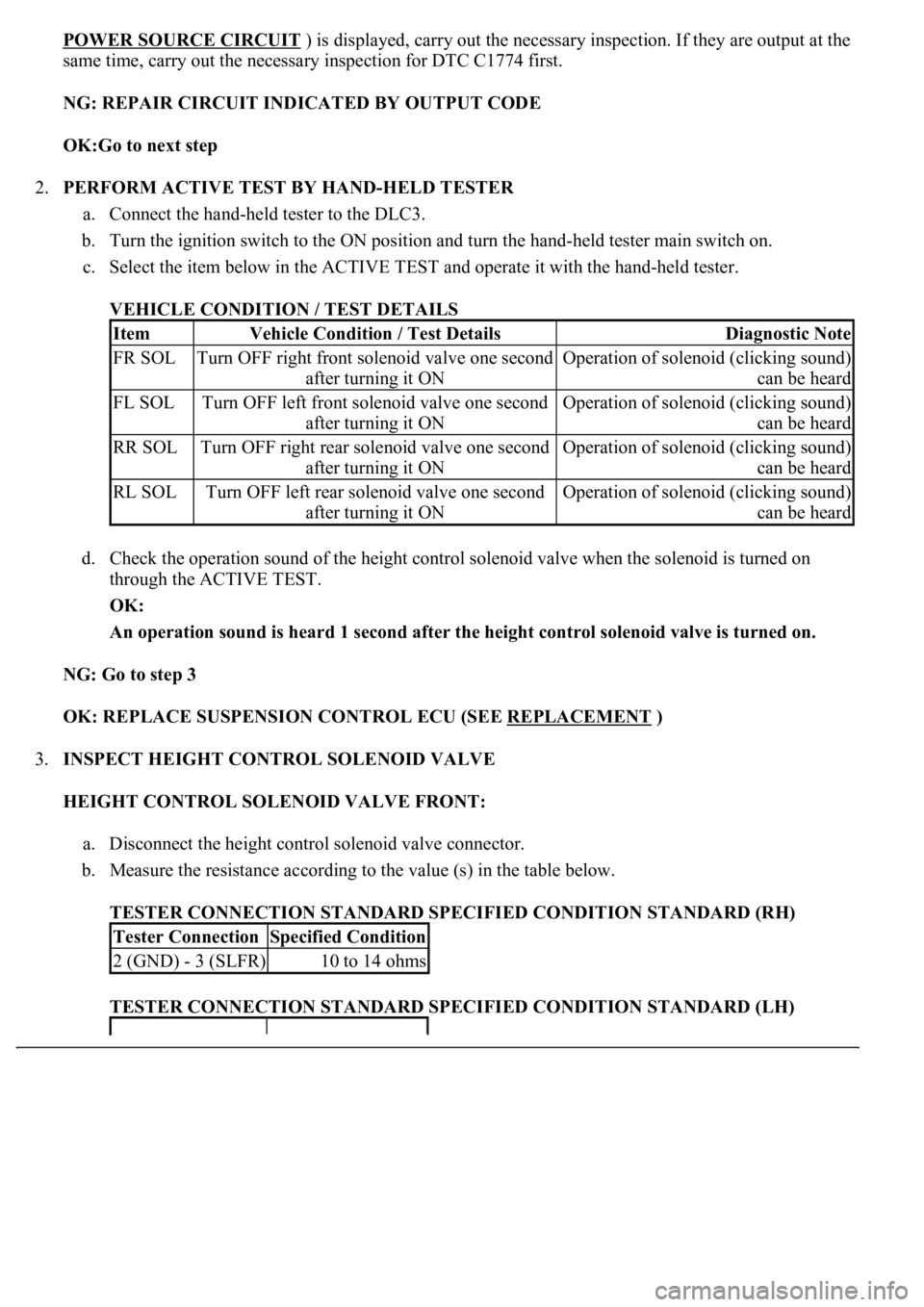
2.PERFORM ACTIVE TEST BY HAND-HELD TESTER
a. Connect the hand-held tester to the DLC3.
b. Turn the ignition switch to the ON position and turn the hand-held tester main switch on.
c. Select the item below in the ACTIVE TEST and operate it with the hand-held tester.
VEHICLE CONDITION / TEST DETAILS
d. Check the operation sound of the height control solenoid valve when the solenoid is turned on
through the ACTIVE TEST.
OK:
An operation sound is heard 1 second after the height control solenoid valve is turned on.
NG: Go to step 3
OK: REPLACE SUSPENSION CONTROL ECU (SEE REPLACEMENT
)
3.INSPECT HEIGHT CONTROL SOLENOID VALVE
HEIGHT CONTROL SOLENOID VALVE FRONT:
a. Disconnect the height control solenoid valve connector.
b. Measure the resistance according to the value (s) in the table below.
TESTER CONNECTION STANDARD SPECIFIED CONDITION STANDARD (RH)
TESTER CONNECTION STANDARD SPECIFIED CONDITION STANDARD (LH)
ItemVehicle Condition / Test DetailsDiagnostic Note
FR SOLTurn OFF right front solenoid valve one second
after turning it ONOperation of solenoid (clicking sound)
can be heard
FL SOLTurn OFF left front solenoid valve one second
after turning it ONOperation of solenoid (clicking sound)
can be heard
RR SOLTurn OFF right rear solenoid valve one second
after turning it ONOperation of solenoid (clicking sound)
can be heard
RL SOLTurn OFF left rear solenoid valve one second
after turning it ONOperation of solenoid (clicking sound)
can be heard
Tester ConnectionSpecified Condition
2 (GND) - 3 (SLFR)10 to 14 ohms
Page 568 of 4500
POWER SOURCE CIRCUIT ) is displayed, carry out the necessary inspection. If they are output at the
same time, carry out the necessary inspection for DTC C1774 first.
NG: REPAIR CIRCUIT INDICATED BY OUTPUT CODE
OK:Go to next step
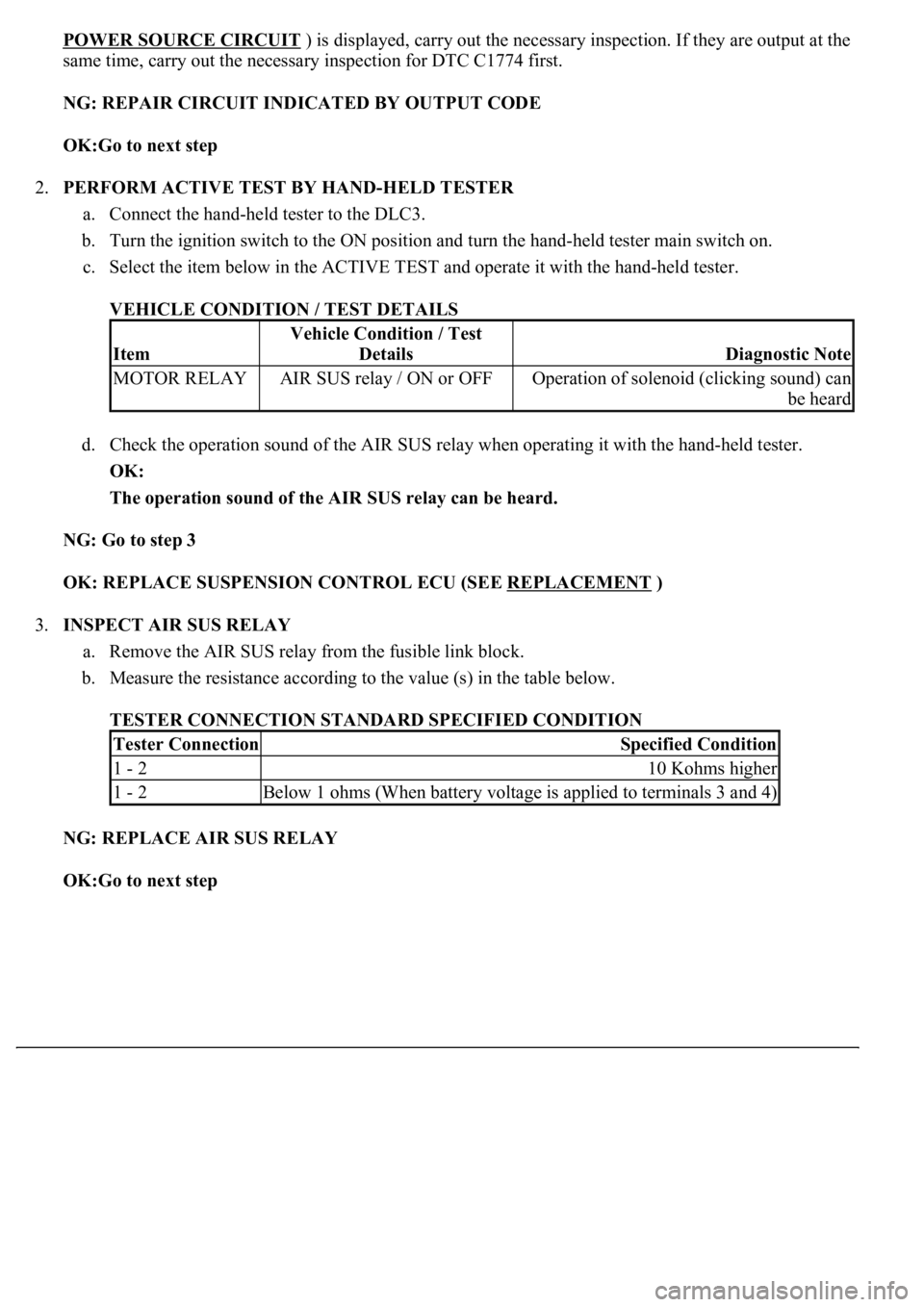
2.PERFORM ACTIVE TEST BY HAND-HELD TESTER
a. Connect the hand-held tester to the DLC3.
b. Turn the ignition switch to the ON position and turn the hand-held tester main switch on.
c. Select the item below in the ACTIVE TEST and operate it with the hand-held tester.
VEHICLE CONDITION / TEST DETAILS
d. Check the operation sound of the AIR SUS relay when operating it with the hand-held tester.
OK:
The operation sound of the AIR SUS relay can be heard.
NG: Go to step 3
OK: REPLACE SUSPENSION CONTROL ECU (SEE REPLACEMENT
)
3.INSPECT AIR SUS RELAY
a. Remove the AIR SUS relay from the fusible link block.
b. Measure the resistance according to the value (s) in the table below.
TESTER CONNECTION STANDARD SPECIFIED CONDITION
NG: REPLACE AIR SUS RELAY
OK:Go to next step
Item
Vehicle Condition / Test
Details
Diagnostic Note
MOTOR RELAYAIR SUS relay / ON or OFFOperation of solenoid (clicking sound) can
be heard
Tester ConnectionSpecified Condition
1 - 210 Kohms higher
1 - 2Below 1 ohms (When battery voltage is applied to terminals 3 and 4)
Page 587 of 4500

10.INSPECT FOR CLOGGED AIR TUBE
a. Check the air tube visually for a clog or damage (see ON
-VEHICLE INSPECTION ).
OK:
Air tube is not clogged or damaged.
NG: REPAIR OR REPLACE AIR TUBE
OK: REPLACE SUSPENSION CONTROL ECU (SEE REPLACEMENT
)
CIRCUIT DESCRIPTION
The signal from the suspension control ECU operates the AIR SUS relay and the height control compressor
motor starts.
The height control compressor motor operates until the targeted vehicle height is reached. Then the height
control sensor sub-assy sends the signal to the suspension control ECU, and stops the height control compressor
motor.
Fig. 104: DTC C1751 And DTC C1752 Detecting Condition And Trouble Area
Courtesy of TOYOTA MOTOR SALES, U.S.A., INC.
INSPECTION PROCEDURE
1.CHECK HEIGHT CONTROL COMPRESSOR CIRCUIT (SEE DTC C1742 HEIGHT
CONTROL COMPRESSOR CIRCUIT )
2.CHECK AIR LEAKAGE (SEE ON
-VEHICLE INSPECTION )
OK:
No leaks
Page 593 of 4500
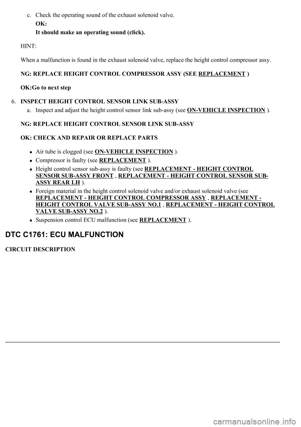
c. Check the operating sound of the exhaust solenoid valve.
OK:
It should make an operating sound (click).
HINT:
When a malfunction is found in the exhaust solenoid valve, replace the height control compressor assy.
NG: REPLACE HEIGHT CONTROL COMPRESSOR ASSY (SEE REPLACEMENT
)
OK:Go to next step
6.INSPECT HEIGHT CONTROL SENSOR LINK SUB-ASSY
a. Inspect and adjust the height control sensor link sub-assy (see ON
-VEHICLE INSPECTION ).
NG: REPLACE HEIGHT CONTROL SENSOR LINK SUB-ASSY
OK: CHECK AND REPAIR OR REPLACE PARTS
Air tube is clogged (see ON-VEHICLE INSPECTION ).
Compressor is faulty (see REPLACEMENT ).
Height control sensor sub-assy is faulty (see REPLACEMENT - HEIGHT CONTROL
SENSOR SUB-ASSY FRONT , REPLACEMENT - HEIGHT CONTROL SENSOR SUB-
ASSY REAR LH ).
Foreign material in the height control solenoid valve and/or exhaust solenoid valve (see
REPLACEMENT
- HEIGHT CONTROL COMPRESSOR ASSY , REPLACEMENT -
HEIGHT CONTROL VALVE SUB
-ASSY NO.1 , REPLACEMENT - HEIGHT CONTROL
VALVE SUB-ASSY NO.2 ).
Suspension control ECU malfunction (see REPLACEMENT ).
CIRCUIT DESCRIPTION
Page 606 of 4500
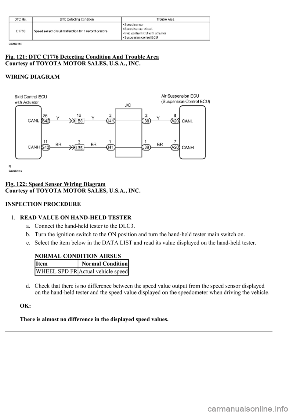
Fig. 121: DTC C1776 Detecting Condition And Trouble Area
Courtesy of TOYOTA MOTOR SALES, U.S.A., INC.
WIRING DIAGRAM
Fig. 122: Speed Sensor Wiring Diagram
Courtesy of TOYOTA MOTOR SALES, U.S.A., INC.
INSPECTION PROCEDURE
1.READ VALUE ON HAND-HELD TESTER
a. Connect the hand-held tester to the DLC3.
b. Turn the ignition switch to the ON position and turn the hand-held tester main switch on.
c. Select the item below in the DATA LIST and read its value displayed on the hand-held tester.
NORMAL CONDITION AIRSUS
d. Check that there is no difference between the speed value output from the speed sensor displayed
on the hand-held tester and the speed value displayed on the speedometer when driving the vehicle.
OK:
There is almost no difference in the displayed speed values.
ItemNormal Condition
WHEEL SPD FRActual vehicle speed
Page 629 of 4500
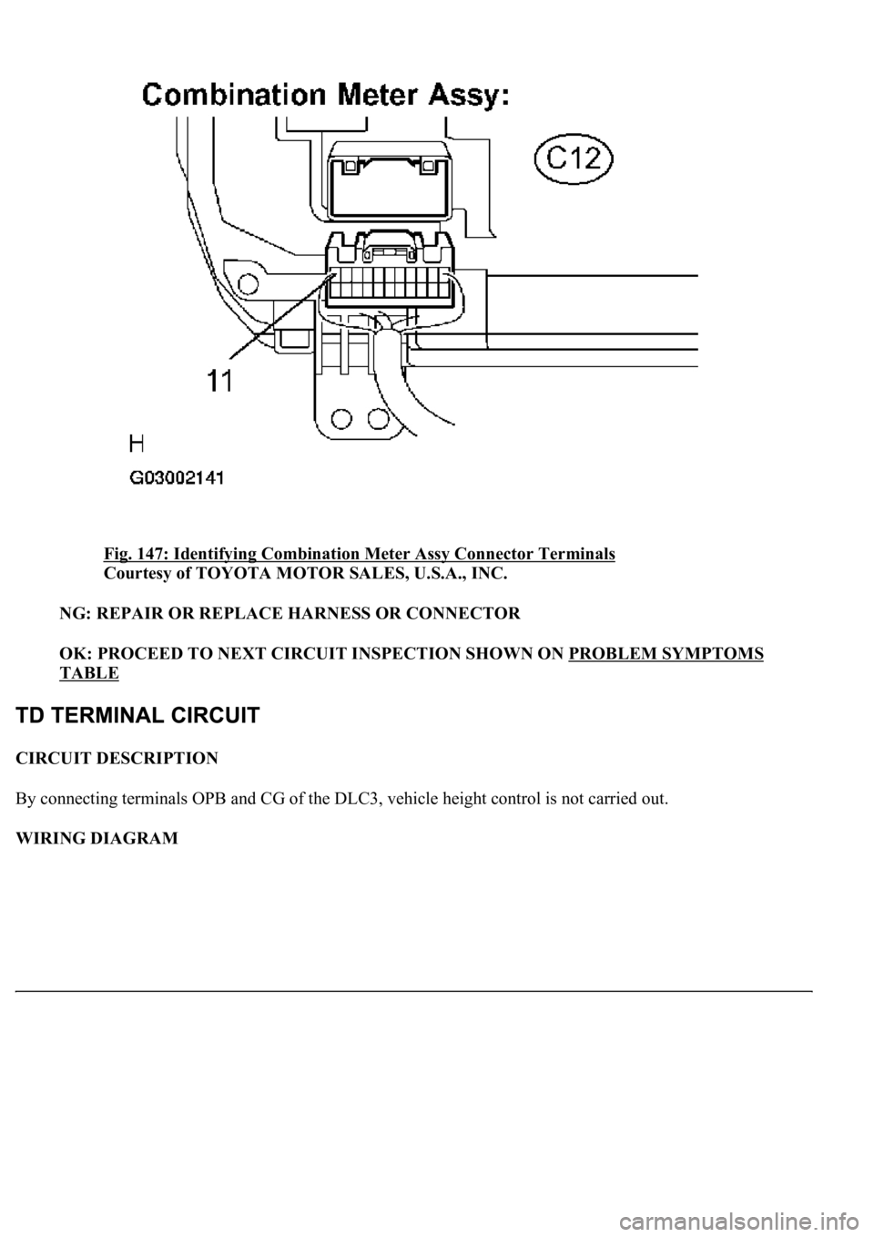
Fig. 147: Identifying Combination Meter Assy Connector Terminals
Courtesy of TOYOTA MOTOR SALES, U.S.A., INC.
NG: REPAIR OR REPLACE HARNESS OR CONNECTOR
OK: PROCEED TO NEXT CIRCUIT INSPECTION SHOWN ON PROBLEM SYMPTOMS
TABLE
CIRCUIT DESCRIPTION
By connecting terminals OPB and CG of the DLC3, vehicle height control is not carried out.
WIRING DIAGRAM
Page 679 of 4500

Fig. 41: Removing Screws
Courtesy of TOYOTA MOTOR SALES, U.S.A., INC.
5.INSTALL HORN BUTTON ASSY (See step 6 on REPLACEMENT
)
6.INSPECT HORN BUTTON ASSY (See ON
-VEHICLE INSPECTION )
7.SRS WARNING LIGHT (See DIAGNOSIS SYSTEM
)
REPLACEMENT
HINT:
See COMPONENTS - FRONT BUMPER , COMPONENTS - REAR BUMPER .
See LOCATION .
Installation is in the reverse order of removal.
1.REMOVE FRONT BUMPER COVER (See step 5 on REPLACEMENT
)
2.REMOVE REAR BUMPER COVER (See step 12 on REPLACEMENT
)
Page 784 of 4500
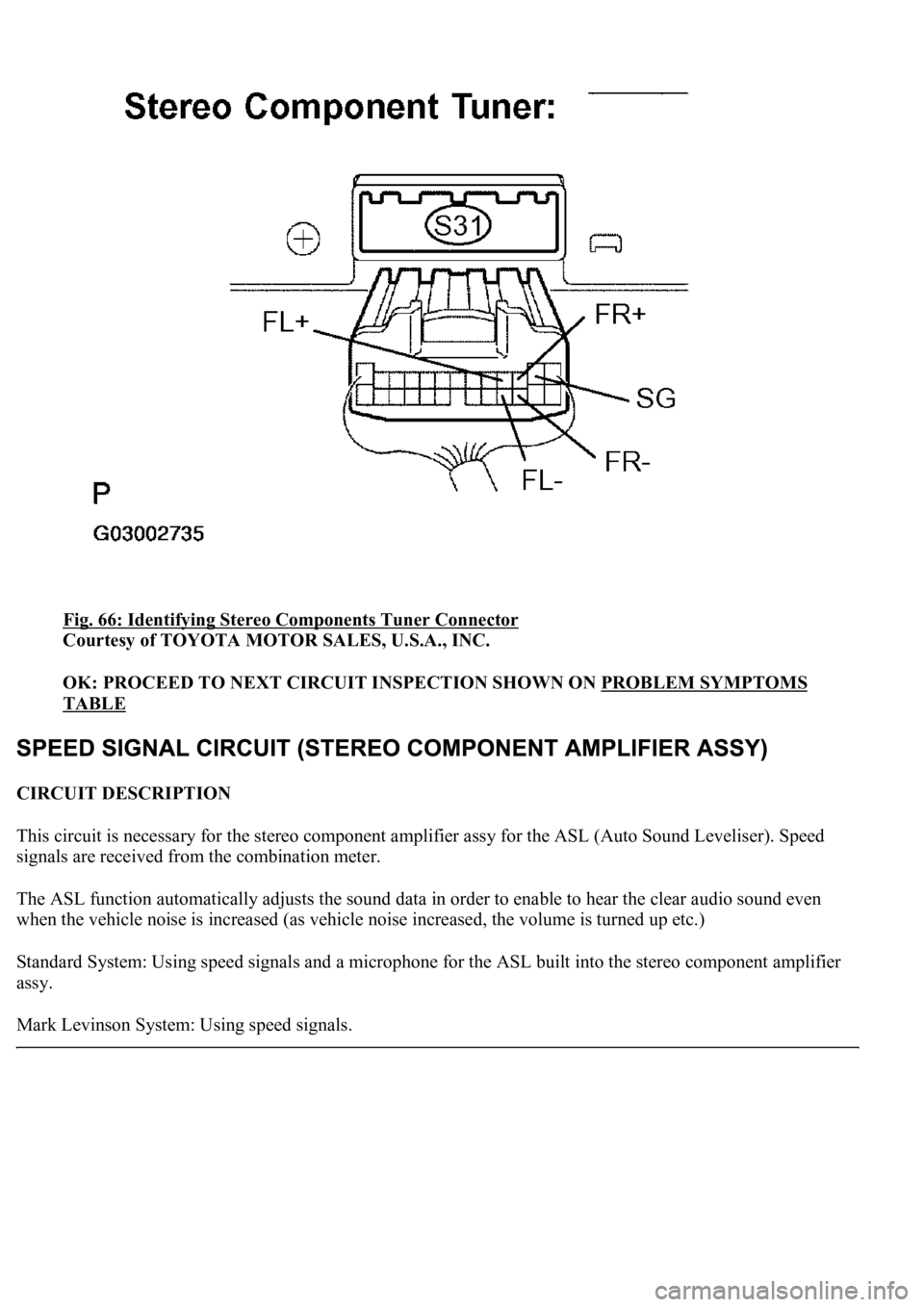
Fig. 66: Identifying Stereo Components Tuner Connector
Courtesy of TOYOTA MOTOR SALES, U.S.A., INC.
OK: PROCEED TO NEXT CIRCUIT INSPECTION SHOWN ON PROBLEM SYMPTOMS
TABLE
CIRCUIT DESCRIPTION
This circuit is necessary for the stereo component amplifier assy for the ASL (Auto Sound Leveliser). Speed
signals are received from the combination meter.
The ASL function automatically adjusts the sound data in order to enable to hear the clear audio sound even
when the vehicle noise is increased (as vehicle noise increased, the volume is turned up etc.)
Standard System: Using speed signals and a microphone for the ASL built into the stereo component amplifier
assy.
Mark Levinson System: Using speed signals.
Page 790 of 4500

Fig. 72: Identifying Blinking Pattern
Courtesy of TOYOTA MOTOR SALES, U.S.A., INC.
NG: GO TO COMBINATION METER SYSTEM (SEE PRECAUTION
)
OK: PROCEED TO NEXT CIRCUIT INSPECTION SHOWN ON PROBLEM SYMPTOMS
TABLE
CIRCUIT DESCRIPTION
This circuit sends the signal to the stereo component amplifier to mute the noise. Because of that, the noise
produced by changing the sound source ceases.
In addition, this circuit is used to mute the sound when the navigation system performs voice guide.
If there is an open in the circuit, noise can be heard from the speaker when changing the sound source.
When the vehicle is equipped with the navigation system, audio sound keeps coming out from the speaker on
the driver's side while the voice navigation is in operation.
If there is a short in the circuit, even though the stereo component amplifier assy is normal, no sound or only
extremely small sound can be produced.
WIRING DIAGRAM
Page 921 of 4500
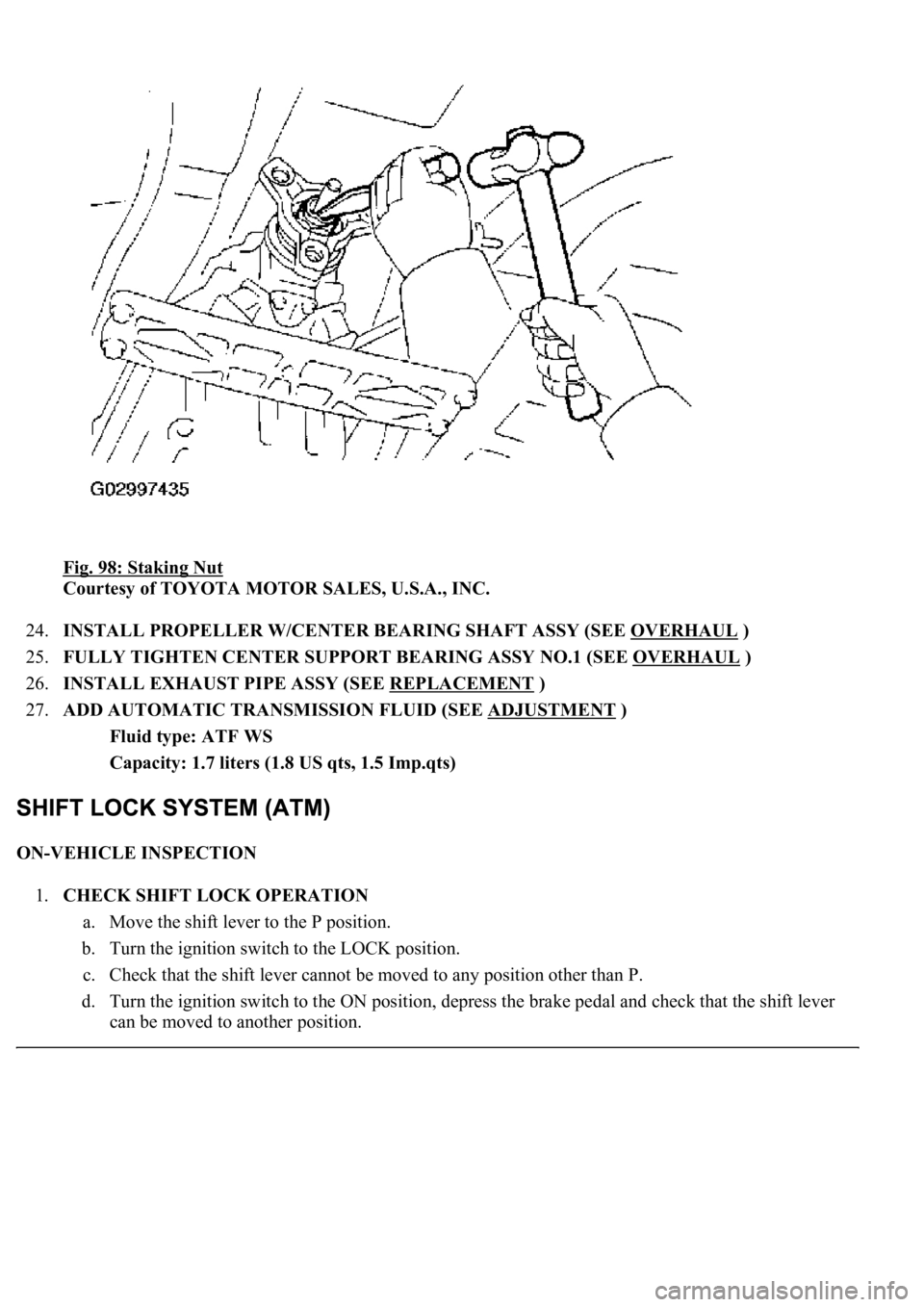
Fig. 98: Staking Nut
Courtesy of TOYOTA MOTOR SALES, U.S.A., INC.
24.INSTALL PROPELLER W/CENTER BEARING SHAFT ASSY (SEE OVERHAUL
)
25.FULLY TIGHTEN CENTER SUPPORT BEARING ASSY NO.1 (SEE OVERHAUL
)
26.INSTALL EXHAUST PIPE ASSY (SEE REPLACEMENT
)
27.ADD AUTOMATIC TRANSMISSION FLUID (SEE ADJUSTMENT
)
Fluid type: ATF WS
Capacity: 1.7 liters (1.8 US qts, 1.5 Imp.qts)
ON-VEHICLE INSPECTION
1.CHECK SHIFT LOCK OPERATION
a. Move the shift lever to the P position.
b. Turn the ignition switch to the LOCK position.
c. Check that the shift lever cannot be moved to any position other than P.
d. Turn the ignition switch to the ON position, depress the brake pedal and check that the shift lever
can be moved to another position.