manual transmission LEXUS LS430 2003 Factory Repair Manual
[x] Cancel search | Manufacturer: LEXUS, Model Year: 2003, Model line: LS430, Model: LEXUS LS430 2003Pages: 4500, PDF Size: 87.45 MB
Page 1605 of 4500
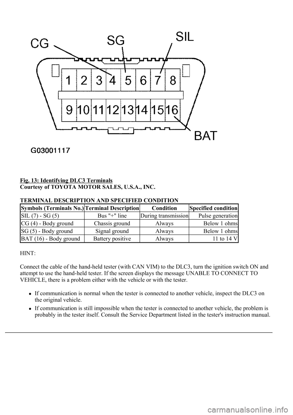
Fig. 13: Identifying DLC3 Terminals
Courtesy of TOYOTA MOTOR SALES, U.S.A., INC.
TERMINAL DESCRIPTION AND SPECIFIED CONDITION
HINT:
Connect the cable of the hand-held tester (with CAN VIM) to the DLC3, turn the ignition switch ON and
attempt to use the hand-held tester. If the screen displays the message UNABLE TO CONNECT TO
VEHICLE, there is a problem either with the vehicle or with the tester.
If communication is normal when the tester is connected to another vehicle, inspect the DLC3 on
the original vehicle.
If communication is still impossible when the tester is connected to another vehicle, the problem is
probably in the tester itself. Consult the Service Department listed in the tester's instruction manual.
Symbols (Terminals No.)Terminal DescriptionConditionSpecified condition
SIL (7) - SG (5)Bus "+" lineDuring transmissionPulse generation
CG (4) - Body groundChassis groundAlwaysBelow 1 ohms
SG (5) - Body groundSignal groundAlwaysBelow 1 ohms
BAT (16) - Body groundBattery positiveAlways11 to 14 V
Page 1996 of 4500
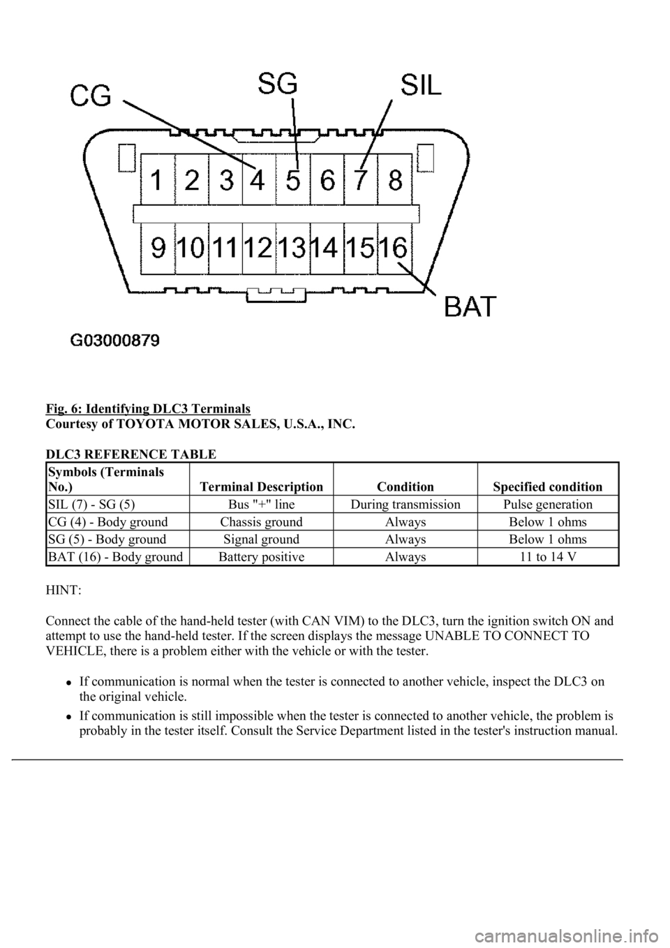
Fig. 6: Identifying DLC3 Terminals
Courtesy of TOYOTA MOTOR SALES, U.S.A., INC.
DLC3 REFERENCE TABLE
HINT:
Connect the cable of the hand-held tester (with CAN VIM) to the DLC3, turn the ignition switch ON and
attempt to use the hand-held tester. If the screen displays the message UNABLE TO CONNECT TO
VEHICLE, there is a problem either with the vehicle or with the tester.
If communication is normal when the tester is connected to another vehicle, inspect the DLC3 on
the original vehicle.
If communication is still impossible when the tester is connected to another vehicle, the problem is
probabl
y in the tester itself. Consult the Service Department listed in the tester's instruction manual.
Symbols (Terminals
No.)
Terminal DescriptionConditionSpecified condition
SIL (7) - SG (5)Bus "+" lineDuring transmissionPulse generation
CG (4) - Body groundChassis groundAlwaysBelow 1 ohms
SG (5) - Body groundSignal groundAlwaysBelow 1 ohms
BAT (16) - Body groundBattery positiveAlways11 to 14 V
Page 2196 of 4500
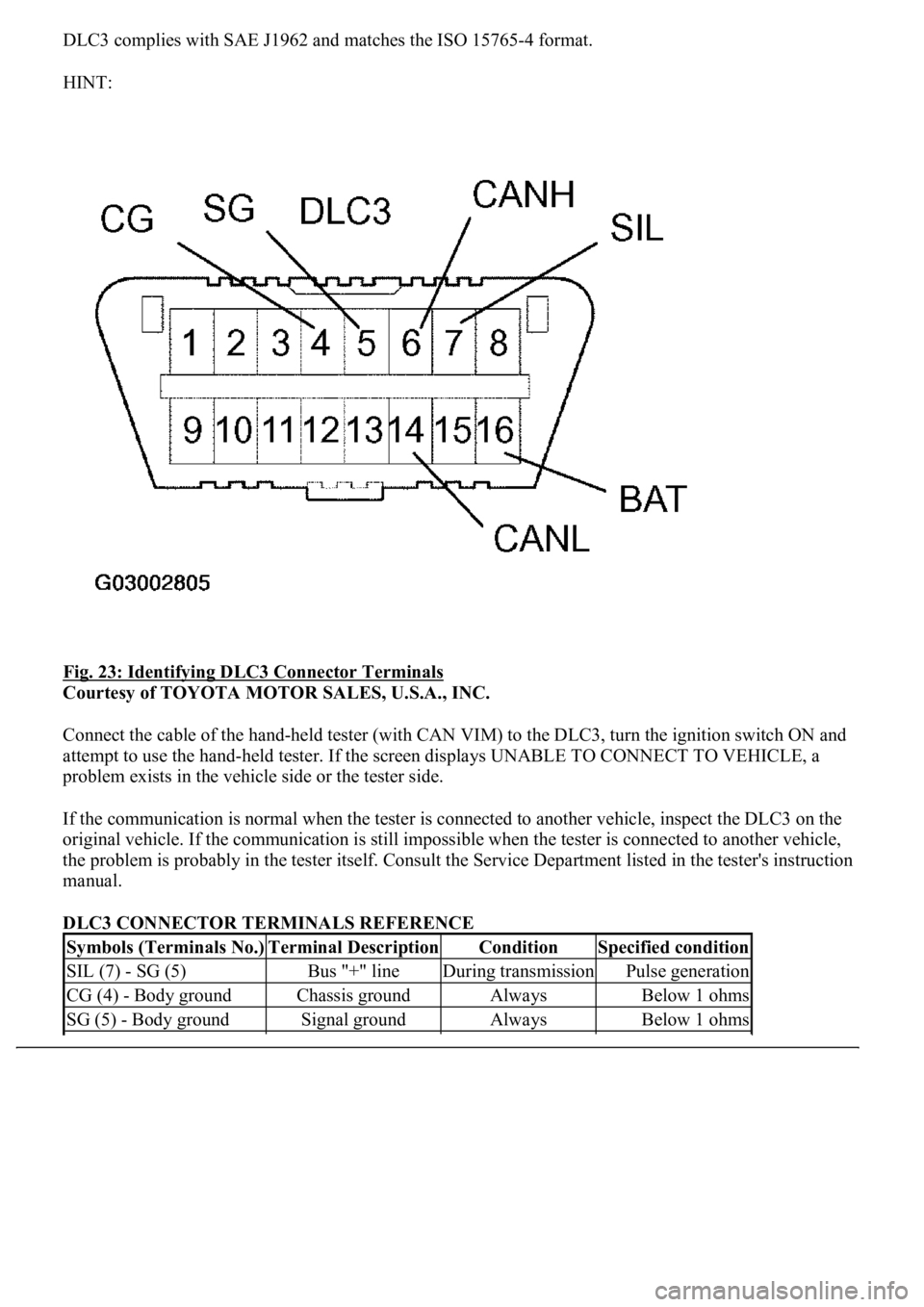
DLC3 complies with SAE J1962 and matches the ISO 15765-4 format.
HINT:
Fig. 23: Identifying DLC3 Connector Terminals
Courtesy of TOYOTA MOTOR SALES, U.S.A., INC.
Connect the cable of the hand-held tester (with CAN VIM) to the DLC3, turn the ignition switch ON and
attempt to use the hand-held tester. If the screen displays UNABLE TO CONNECT TO VEHICLE, a
problem exists in the vehicle side or the tester side.
If the communication is normal when the tester is connected to another vehicle, inspect the DLC3 on the
original vehicle. If the communication is still impossible when the tester is connected to another vehicle,
the problem is probably in the tester itself. Consult the Service Department listed in the tester's instruction
manual.
DLC3 CONNECTOR TERMINALS REFERENCE
Symbols (Terminals No.)Terminal DescriptionConditionSpecified condition
SIL (7) - SG (5)Bus "+" lineDuring transmissionPulse generation
CG (4) - Body groundChassis groundAlwaysBelow 1 ohms
SG (5) - Body groundSignal groundAlwaysBelow 1 ohms
Page 2685 of 4500
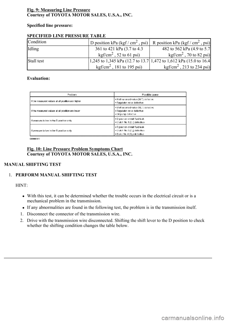
Fig. 9: Measuring Line Pressure
Courtesy of TOYOTA MOTOR SALES, U.S.A., INC.
Specified line pressure:
SPECIFIED LINE PRESSURE TABLE
Evaluation:
Fig. 10: Line Pressure Problem Symptoms Chart
Courtesy of TOYOTA MOTOR SALES, U.S.A., INC.
MANUAL SHIFTING TEST
1.PERFORM MANUAL SHIFTING TEST
HINT:
With this test, it can be determined whether the trouble occurs in the electrical circuit or is a
mechanical problem in the transmission.
If any abnormalities are found in the following test, the problem is in the transmission itself.
1. Disconnect the connector of the transmission wire.
2. Drive with the transmission wire disconnected. Shifting the shift lever to the D position to check
<005a004b00480057004b0048005500030057004b004800030056004b004c00490057004c0051004a00030046005200510047004c0057004c0052005100030046004b00440051004a0048005600030057004b00480003005700440045004f00480003004500
48004f0052005a00110003[
ConditionD position kPa (kgf / cm2 , psi)R position kPa (kgf / cm2 , psi)
Idling361 to 421 kPa (3.7 to 4.3
kgf/cm
2 , 52 to 61 psi)
482 to 562 kPa (4.9 to 5.7
kgf/cm
2 , 70 to 82 psi)
Stall test1,245 to 1,345 kPa (12.7 to 13.7
kgf/cm
2 , 181 to 195 psi)
1,472 to 1,612 kPa (15.0 to 16.4
kgf/cm
2 , 213 to 234 psi)
Page 2686 of 4500
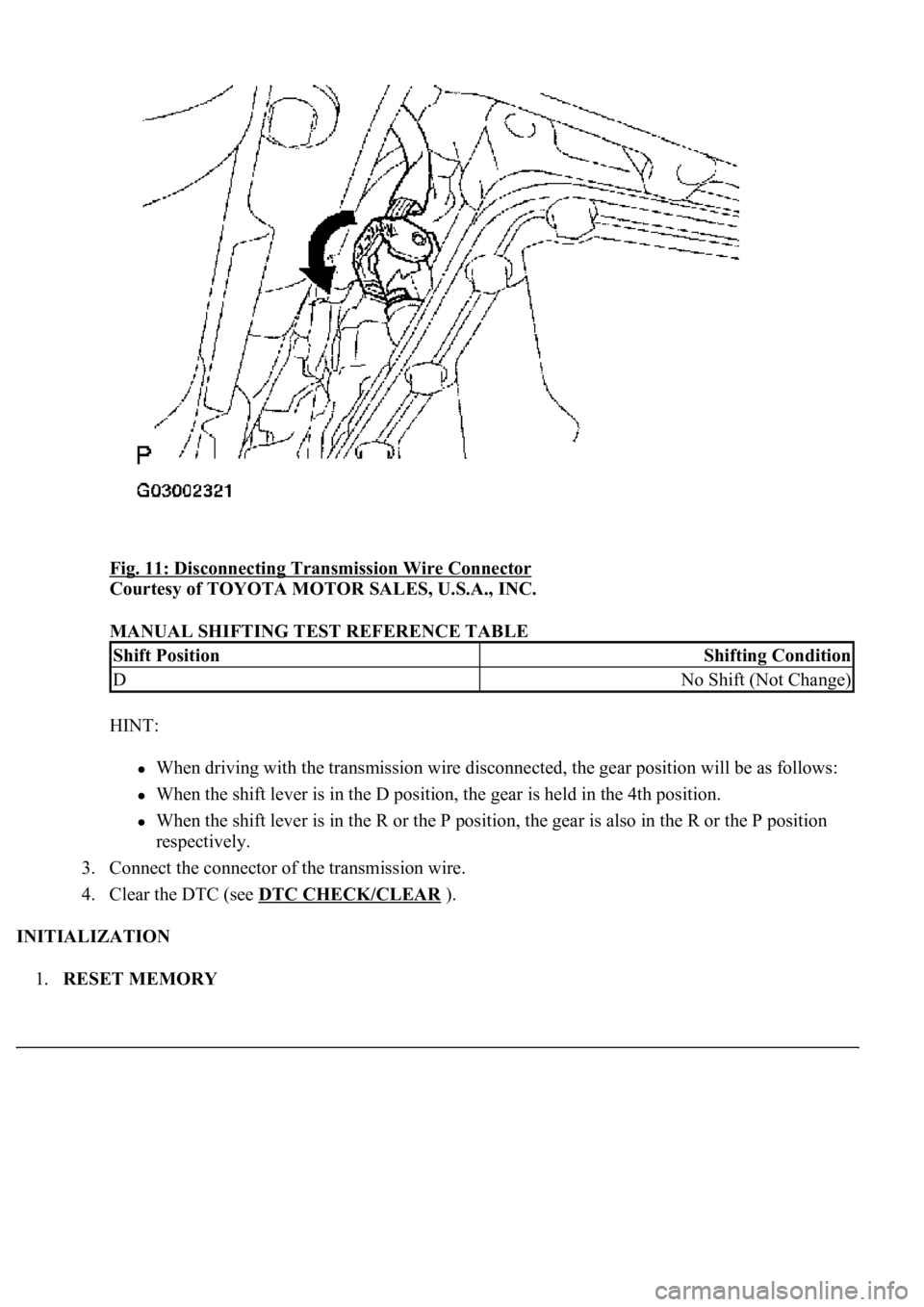
Fig. 11: Disconnecting Transmission Wire Connector
Courtesy of TOYOTA MOTOR SALES, U.S.A., INC.
MANUAL SHIFTING TEST REFERENCE TABLE
HINT:
When driving with the transmission wire disconnected, the gear position will be as follows:
When the shift lever is in the D position, the gear is held in the 4th position.
When the shift lever is in the R or the P position, the gear is also in the R or the P position
respectively.
3. Connect the connector of the transmission wire.
4. Clear the DTC (see DTC CHECK/CLEAR
).
INITIALIZATION
1.RESET MEMORY
Shift PositionShifting Condition
DNo Shift (Not Change)
Page 2856 of 4500
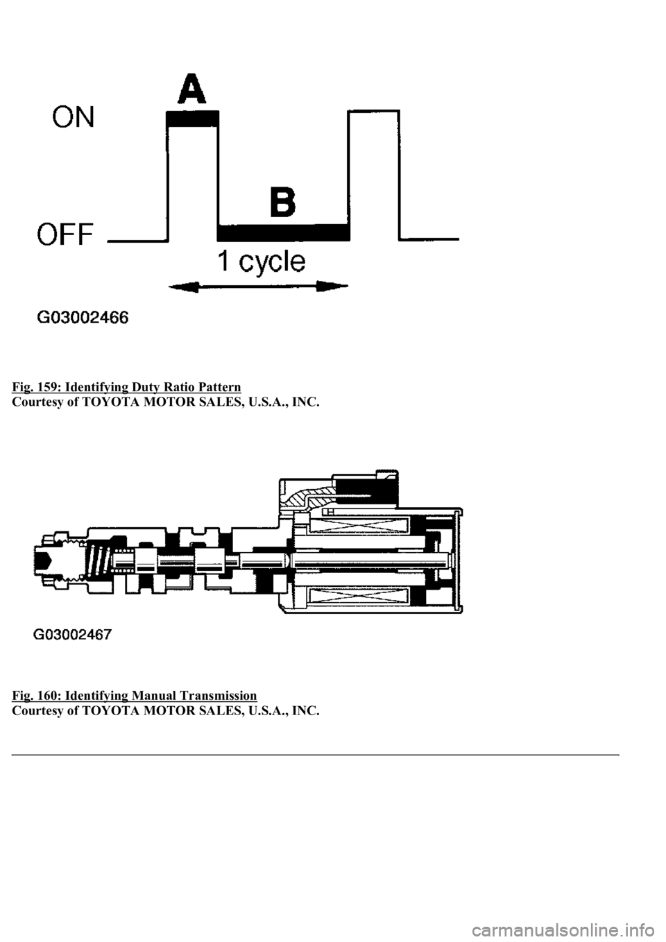
Fig. 159: Identifying Duty Ratio Pattern
Courtesy of TOYOTA MOTOR SALES, U.S.A., INC.
Fig. 160: Identifying Manual Transmission
Courtesy of TOYOTA MOTOR SALES, U.S.A., INC.
Page 2869 of 4500
OK: REPAIR OR REPLACE TRANSMISSION WIRE (See step 5 on REPLACEMENT)
DTC P2757: TORQUE CONVERTER CLUTCH PRESSURE CONTROL SOLENOID
PERFORMANCE (SHIFT SOLENOID VALVE SLU)
SYSTEM DESCRIPTION
The ECM uses the signals from the throttle position sensor, Air-flow meter, turbine (input) speed sensor, output
speed sensor and crankshaft position sensor to monitor the engagement condition of the lock-up clutch.
Then the ECM compares the engagement condition of the lock-up clutch with the lock-up schedule in the ECM
memory to detect a mechanical problems of the shift solenoid valve SLU, valve body and torque converter
clutch.
Fig. 173: Identifying Manual Transmission
Courtesy of TOYOTA MOTOR SALES, U.S.A., INC.
Page 3925 of 4500
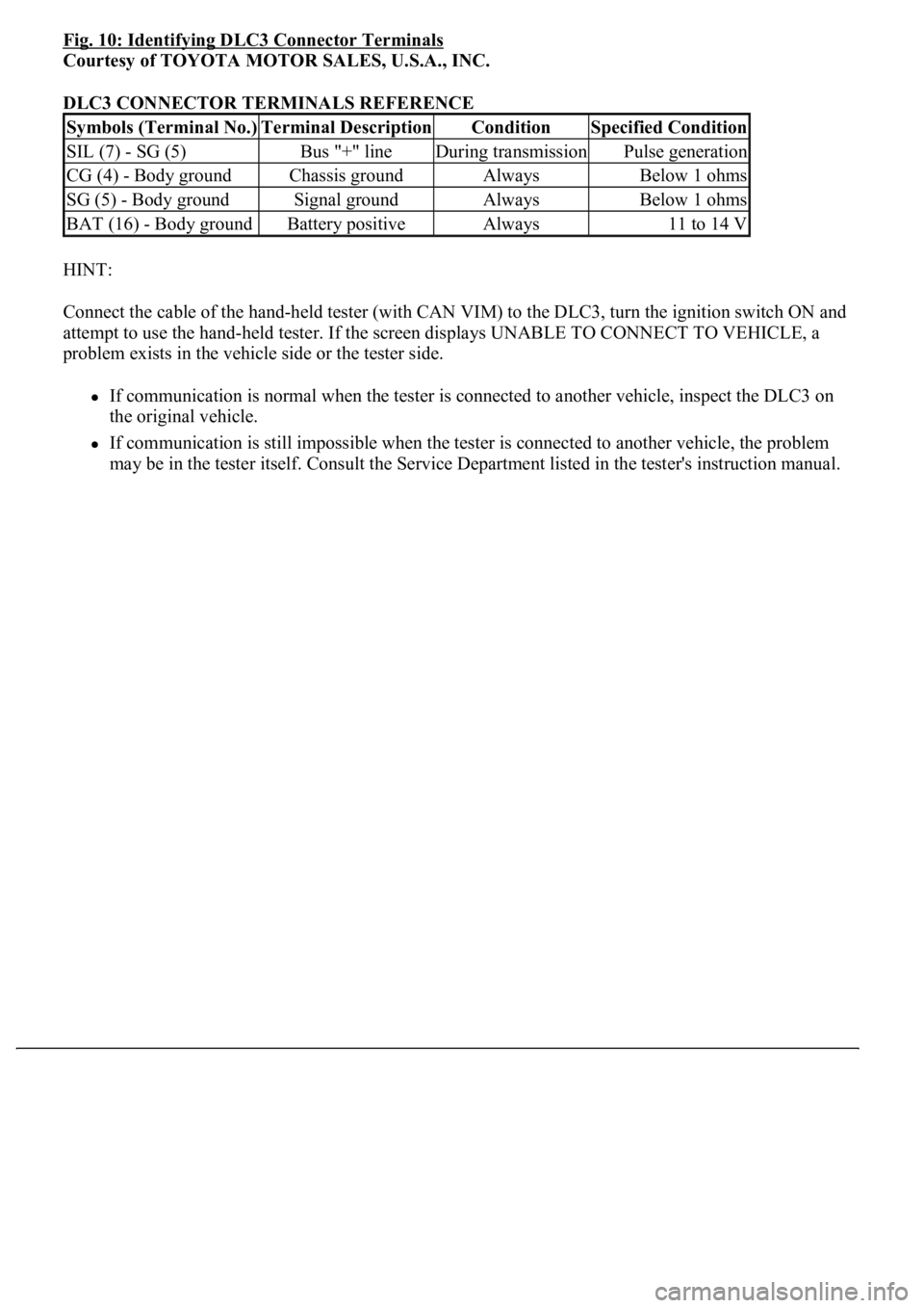
Fig. 10: Identifying DLC3 Connector Terminals
Courtesy of TOYOTA MOTOR SALES, U.S.A., INC.
DLC3 CONNECTOR TERMINALS REFERENCE
HINT:
Connect the cable of the hand-held tester (with CAN VIM) to the DLC3, turn the ignition switch ON and
attempt to use the hand-held tester. If the screen displays UNABLE TO CONNECT TO VEHICLE, a
problem exists in the vehicle side or the tester side.
If communication is normal when the tester is connected to another vehicle, inspect the DLC3 on
the original vehicle.
If communication is still impossible when the tester is connected to another vehicle, the problem
may be in the tester itself. Consult the Service Department listed in the tester's instruction manual.
Symbols (Terminal No.)Terminal DescriptionConditionSpecified Condition
SIL (7) - SG (5)Bus "+" lineDuring transmissionPulse generation
CG (4) - Body groundChassis groundAlwaysBelow 1 ohms
SG (5) - Body groundSignal groundAlwaysBelow 1 ohms
BAT (16) - Body groundBattery positiveAlways11 to 14 V