LEXUS LS430 2003 Factory Owner's Manual
LS430 2003
LEXUS
LEXUS
https://www.carmanualsonline.info/img/36/57050/w960_57050-0.png
LEXUS LS430 2003 Factory Owner's Manual
Page 2061 of 4500
If the runout is greater than the maximum, replace the drive pinion and ring gear.
Fig. 21: Inspecting Runout Of Differential Drive Pinion
Courtesy of TOYOTA MOTOR SALES, U.S.A., INC.
22.INSPECT DIFFERENTIAL DRIVE PINION PRELOAD
a. Using SST and a torque wrench, measure the preload using the backlash of the drive pinion and
ring gear.
SST 09229-55010
Drive pinion preload (at starting):
0.5 to 0.8 N.m (5 to 8 kgf.cm, 4.3 to 6.9 in..lbf)
If the preload is not within the specification, adjust the rear differential drive pinion preload or repair as
necessar
y.
Page 2062 of 4500
Fig. 22: Inspecting Differential Drive Pinion Preload
Courtesy of TOYOTA MOTOR SALES, U.S.A., INC.
23.INSPECT TOTAL PRELOAD
a. Using SST and a torque wrench, measure the preload with the teeth of the drive pinion and ring
gear in contact.
SST 09229-55010
Total preload (at starting):
Drive pinion preload plus 0.46 to 1.37 N.m
(4.69 to 13.97 kgf.cm, 4.07 to 12.13 in..lbf)
If necessary, disassemble and inspect the differential.
Page 2063 of 4500
Fig. 23: Inspecting Total Preload
Courtesy of TOYOTA MOTOR SALES, U.S.A., INC.
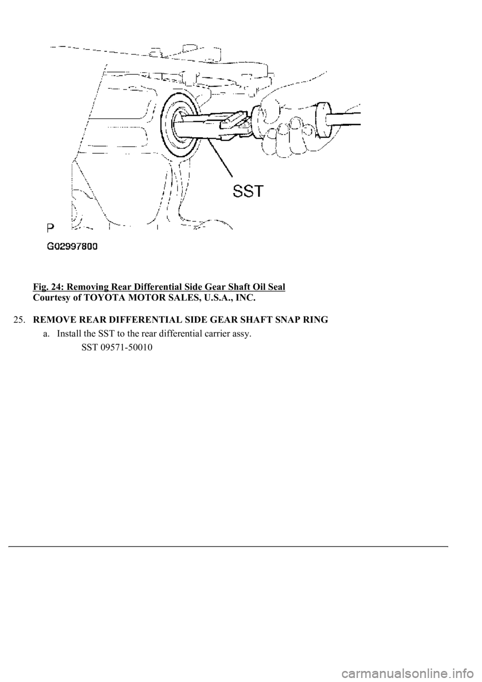
24.REMOVE REAR DIFFERENTIAL SIDE GEAR SHAFT OIL SEAL
a. Using SST, remove the 2 oil seals.
SST 09308-00010
Page 2064 of 4500
Fig. 24: Removing Rear Differential Side Gear Shaft Oil Seal
Courtesy of TOYOTA MOTOR SALES, U.S.A., INC.
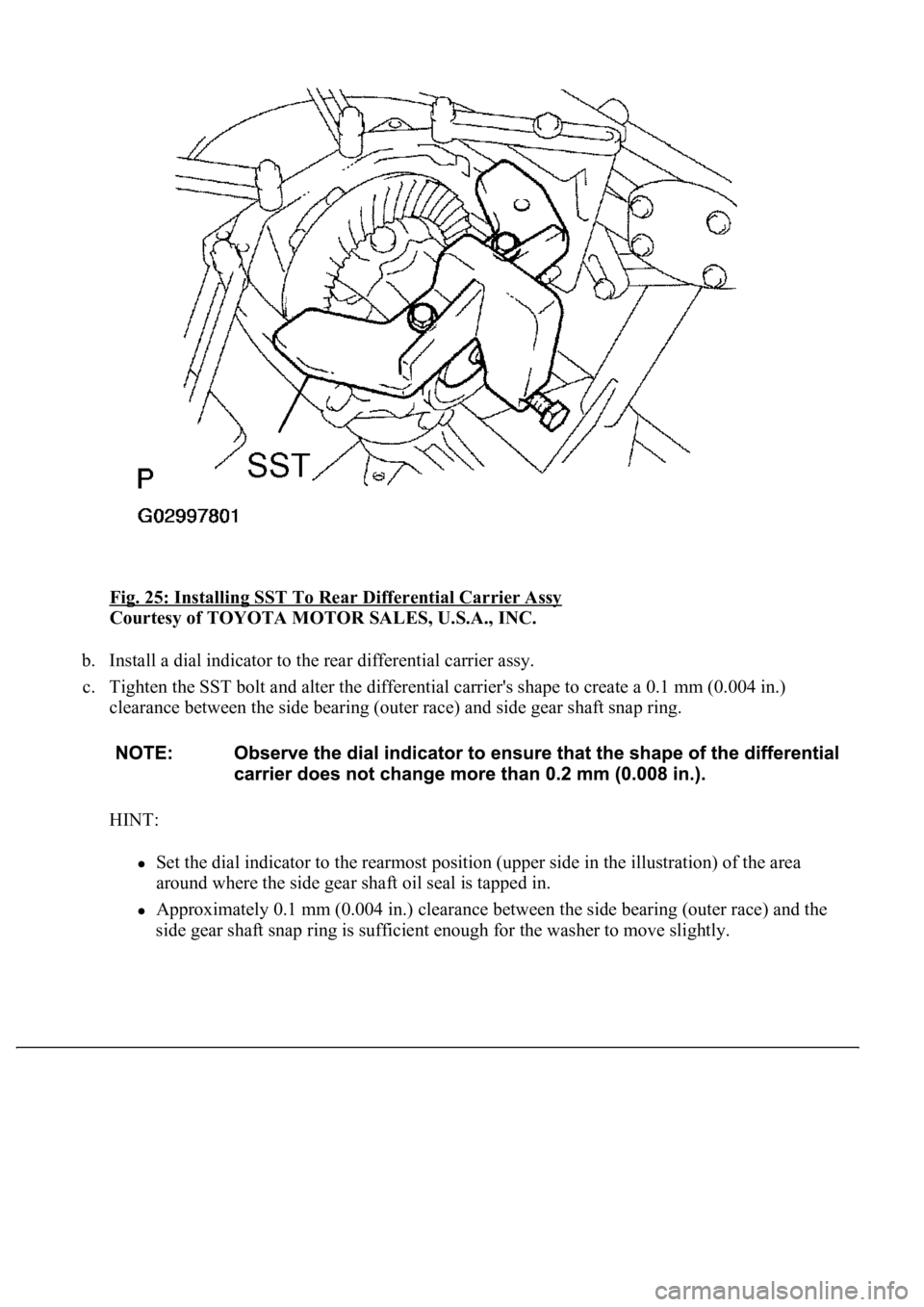
25.REMOVE REAR DIFFERENTIAL SIDE GEAR SHAFT SNAP RING
a. Install the SST to the rear differential carrier assy.
SST 09571-50010
Page 2065 of 4500
Fig. 25: Installing SST To Rear Differential Carrier Assy
Courtesy of TOYOTA MOTOR SALES, U.S.A., INC.
b. Install a dial indicator to the rear differential carrier assy.
c. Tighten the SST bolt and alter the differential carrier's shape to create a 0.1 mm (0.004 in.)
clearance between the side bearing (outer race) and side gear shaft snap ring.
HINT:
Set the dial indicator to the rearmost position (upper side in the illustration) of the area
around where the side gear shaft oil seal is tapped in.
Approximately 0.1 mm (0.004 in.) clearance between the side bearing (outer race) and the
side
gear shaft snap ring is sufficient enough for the washer to move slightly.
Page 2067 of 4500
Fig. 27: Removing Side Gear Shaft Snap Ring On Drive Pinion Side
Courtesy of TOYOTA MOTOR SALES, U.S.A., INC.
26.REMOVE REAR DIFFERENTIAL SIDE GEAR SHAFT SNAP RING
a. Using SST and a hammer, create a clearance between the side bearing (outer race) on the ring gear
and side gear shaft snap ring.
SST 09608-32010, 09950-70010 (09951-07200)
HINT:
The clearance cannot be seen, but tapping the SST with a hammer three or four times should be
enou
gh.
Page 2069 of 4500
Fig. 29: Removing Side Gear Shaft Snap Ring On Ring Gear Side
Courtesy of TOYOTA MOTOR SALES, U.S.A., INC.
27.REMOVE REAR DIFFERENTIAL CASE BEARING
a. Tighten the SST bolt and push out the outer race on the ring gear side.
SST 09571-50010
b. Remove the SST.
Page 2070 of 4500
Fig. 30: Removing Outer Race On Ring Gear Side
Courtesy of TOYOTA MOTOR SALES, U.S.A., INC.
28.REMOVE REAR DIFFERENTIAL CASE BEARING
a. Raise the ring gear of the differential case slightly to remove the drive pinion side outer race.
HINT:
For reassembly, check the installation position of the outer race and the side gear shaft snap ring before
removing the outer race. Write down the result.
Page 2071 of 4500
Fig. 31: Removing Rear Differential Case Bearing
Courtesy of TOYOTA MOTOR SALES, U.S.A., INC.
29.REMOVE REAR DIFFERENTIAL CASE SUB-ASSY
Page 2072 of 4500
Fig. 32: Removing Rear Differential Case Sub-Assy
Courtesy of TOYOTA MOTOR SALES, U.S.A., INC.
30.REMOVE REAR DRIVE PINION NUT
a. Using SST and a hammer, loosen the staked part of the nut.
SST 09930-00010