relay LEXUS LS430 2003 Factory Owner's Manual
[x] Cancel search | Manufacturer: LEXUS, Model Year: 2003, Model line: LS430, Model: LEXUS LS430 2003Pages: 4500, PDF Size: 87.45 MB
Page 403 of 4500
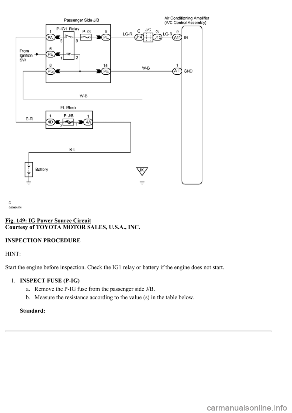
Fig. 149: IG Power Source Circuit
Courtesy of TOYOTA MOTOR SALES, U.S.A., INC.
INSPECTION PROCEDURE
HINT:
Start the engine before inspection. Check the IG1 relay or battery if the engine does not start.
1.INSPECT FUSE (P-IG)
a. Remove the P-IG fuse from the passenger side J/B.
b. Measure the resistance according to the value (s) in the table below.
Standard:
Page 425 of 4500
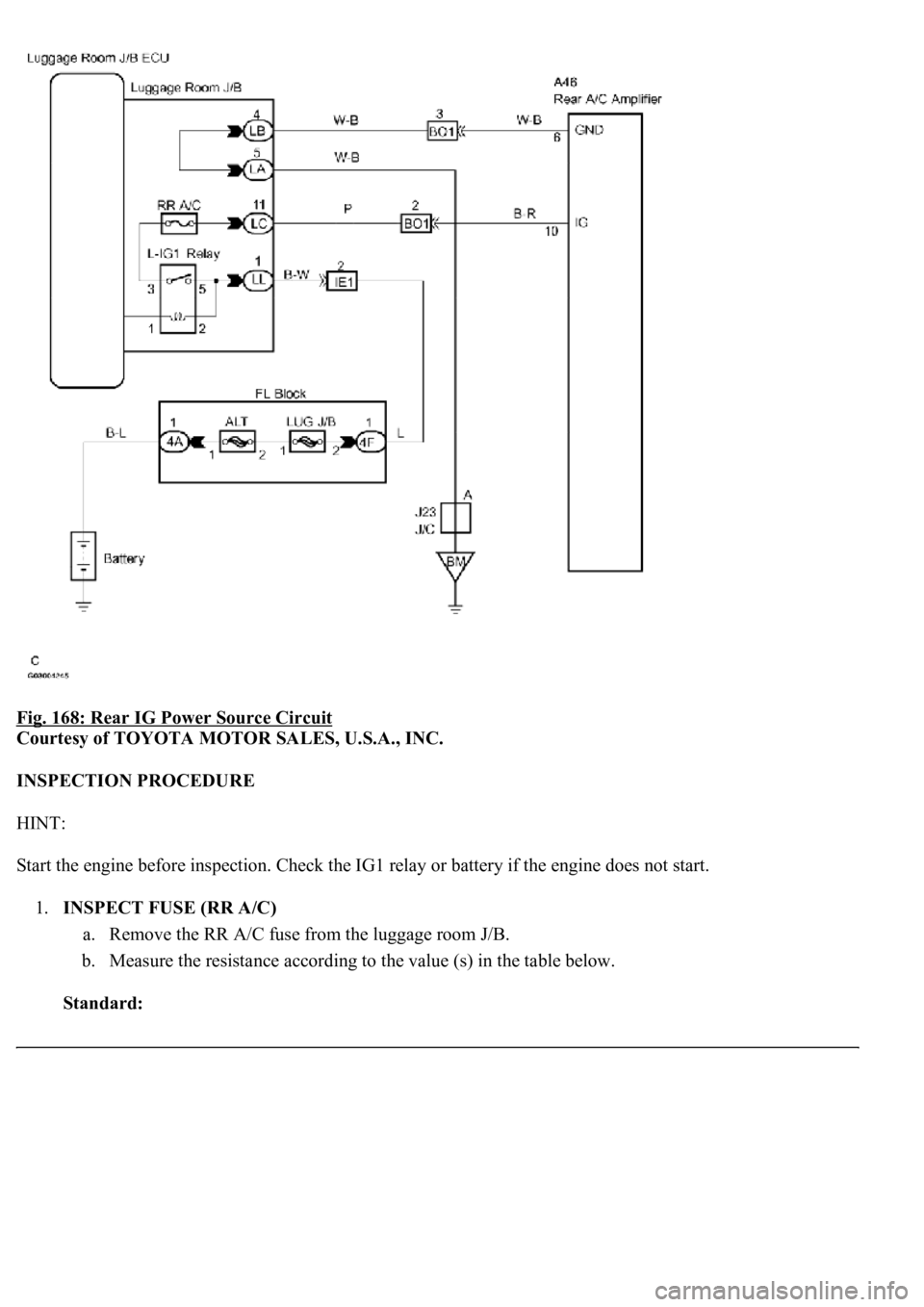
Fig. 168: Rear IG Power Source Circuit
Courtesy of TOYOTA MOTOR SALES, U.S.A., INC.
INSPECTION PROCEDURE
HINT:
Start the engine before inspection. Check the IG1 relay or battery if the engine does not start.
1.INSPECT FUSE (RR A/C)
a. Remove the RR A/C fuse from the luggage room J/B.
b. Measure the resistance according to the value (s) in the table below.
Standard:
Page 480 of 4500
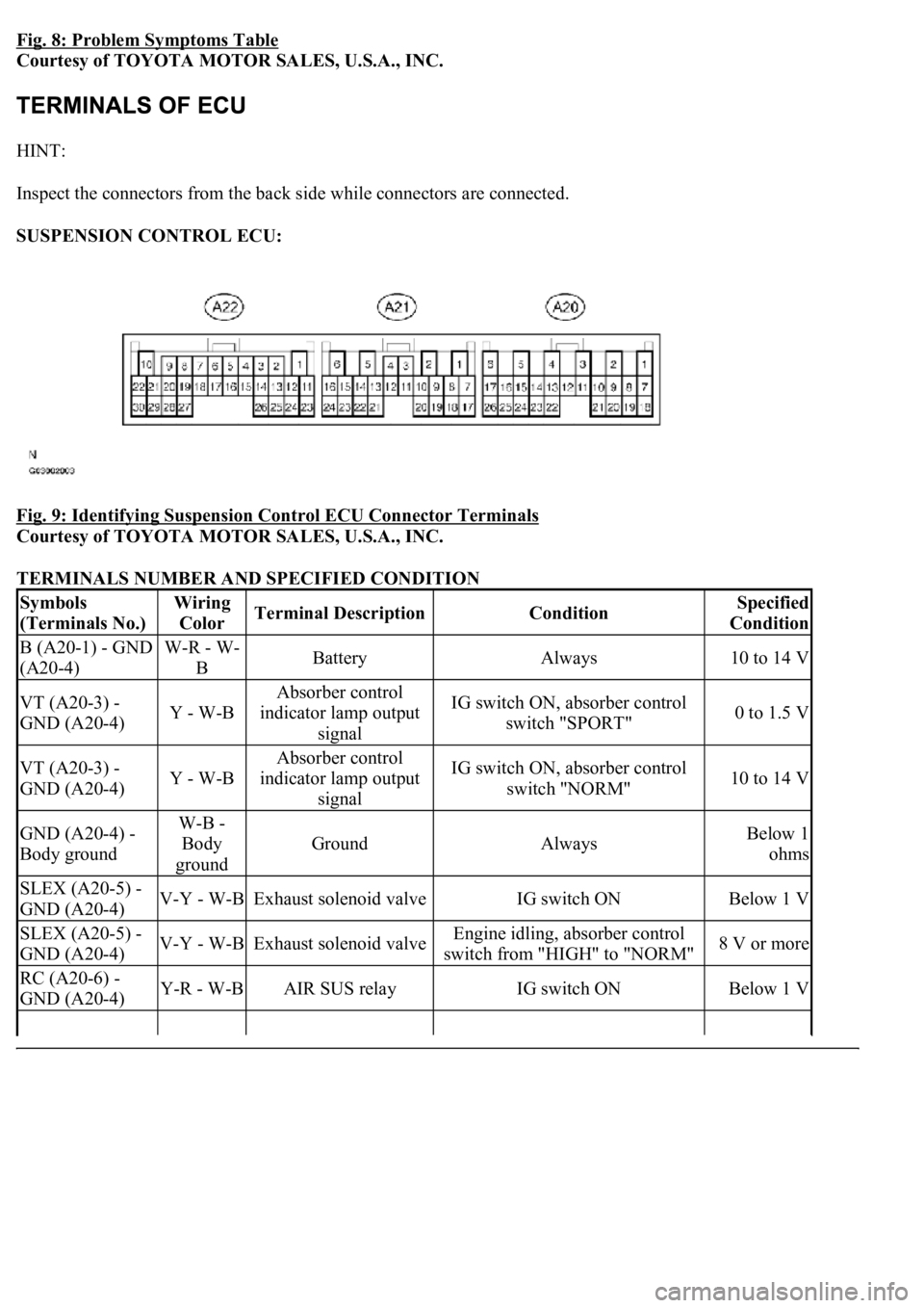
Fig. 8: Problem Symptoms Table
Courtesy of TOYOTA MOTOR SALES, U.S.A., INC.
HINT:
Inspect the connectors from the back side while connectors are connected.
SUSPENSION CONTROL ECU:
Fig. 9: Identifying Suspension Control ECU Connector Terminals
Courtesy of TOYOTA MOTOR SALES, U.S.A., INC.
TERMINALS NUMBER AND SPECIFIED CONDITION
Symbols
(Terminals No.)Wiring
ColorTerminal DescriptionConditionSpecified
Condition
B (A20-1) - GND
(A20-4)W-R - W-
BBatteryAlways10 to 14 V
VT (A20-3) -
GND (A20-4)Y - W-B
Absorber control
indicator lamp output
signalIG switch ON, absorber control
switch "SPORT"0 to 1.5 V
VT (A20-3) -
GND (A20-4)Y - W-B
Absorber control
indicator lamp output
signalIG switch ON, absorber control
switch "NORM"10 to 14 V
GND (A20-4) -
Body groundW-B -
Body
ground
GroundAlwaysBelow 1
ohms
SLEX (A20-5) -
GND (A20-4)V-Y - W-BExhaust solenoid valveIG switch ONBelow 1 V
SLEX (A20-5) -
GND (A20-4)V-Y - W-BExhaust solenoid valveEngine idling, absorber control
switch from "HIGH" to "NORM"8 V or more
RC (A20-6) -
GND (A20-4)Y-R - W-BAIR SUS relayIG switch ONBelow 1 V
Page 481 of 4500

RC (A20-6) -
GND (A20-4)Y-R - W-BAIR SUS relay
Engine idling, height control switch
from "NORM" to "HIGH" during
compressor operation
8 V or more
CANH (A20-7) -
CANL (A20-8)BR - YCAN communication
lineIG switch OFF54 to 67
ohms
SW1 (A20-9) -
GND (A20-4)O - W-BAbsorber control switch
input signalEngine idling, absorber control
switch "NORM" position10 to 14 V
SW1 (A20-9) -
GND (A20-4)O - W-BAbsorber control switch
input signalEngine idling, absorber control
switch "SPORT" position0 to 1.5 V
SIL (A20-13) -
GND (A20-4)W-G - W-
BDiagnosis tester
communication lineIG switch ONPulse
generation
TD (A20-14) -
GND (A20-4)L-B - W-BHeight control is not
operatingIG switch ON10 to 14 V
HSW (A20-15) -
GND (A20-4)LG-B - W-
BHeight control switch
input signalIG switch ON, height control
switch "NORM" position10 to 14 V
HSW (A20-15) -
GND (A20-4)LG-B - W-
BHeight control switch
input signalIG switch ON, height control
switch "HIGH" position0 to 1.5 V
SLFR (A20-16) -
GND (A20-4)G-W - W-
BHeight control solenoid
valve (FR)IG switch ONBelow 1 V
SLFR (A20-16) -
GND (A20-4)G-W - W-
BHeight control solenoid
valve (FR)Engine idling, height control switch
from "NORM" to "HIGH" or
reverse
8 V or more
SLFL (A20-17) -
GND (A20-4)R-W - W-
BHeight control solenoid
valve (FL)IG switch ONBelow 1 V
SLFL (A20-17) -
GND (A20-4)R-W - W-
BHeight control solenoid
valve (FL)Engine idling, height control switch
from "NORM" to "HIGH" or
reverse
8 V or more
SBL1 (A20-18) -
GND (A20-4)LG-R - W-
BHeight control sensor
power source (FL)IG switch ON4.5 to 5.5 V
VH (A20-19) -
GND (A20-4)P - W-BHeight control indicator
output signalIG switch ON, height control
switch "HIGH"0 to 1.5 V
SBR1 (A20-20) -
GND (A20-4)V-R - W-BHeight control indicator
output signalIG switch ON, height control
switch "NORM"10 to 14 V
SBR1 (A20-20) -
GND (A20-4)V-R - W-BHeight control sensor
power source (FR)IG switch ON4.5 to 5.5 V
SGR1 (A20-21) -
GND (A20-4)R-L - W-BHeight control sensor
ground (FR)AlwaysBelow 1
ohms
SGL1 (A20-22) -
GND (A20-4)LG-B - W-
BHeight control sensor
ground (FL)AlwaysBelow 1
ohms
FAR+ (A21-1) -
FAR- (A21-2)O - R-YSuspension control
actuator (FR)IG switch ONBelow 1
ohms
FBR+ (A21-3) -
FBR- (A21-4)R-G - L-GSuspension control
actuator (FR)IG switch ONBelow 1
ohms
FAL+ (A21-5) -
FAL- (A21-14)G-B - G-RSuspension control
actuator (FL)IG switch ONBelow 1
ohms
Page 492 of 4500
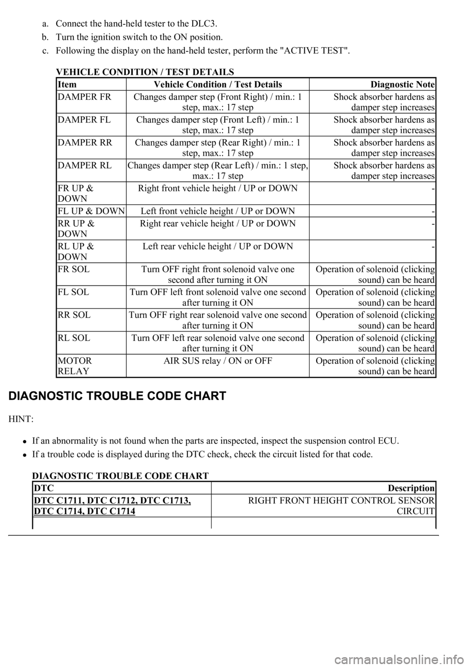
a. Connect the hand-held tester to the DLC3.
b. Turn the ignition switch to the ON position.
c. Following the display on the hand-held tester, perform the "ACTIVE TEST".
VEHICLE CONDITION / TEST DETAILS
HINT:
If an abnormality is not found when the parts are inspected, inspect the suspension control ECU.
If a trouble code is displayed during the DTC check, check the circuit listed for that code.
DIAGNOSTIC TROUBLE CODE CHART
ItemVehicle Condition / Test DetailsDiagnostic Note
DAMPER FRChanges damper step (Front Right) / min.: 1
step, max.: 17 stepShock absorber hardens as
damper step increases
DAMPER FLChanges damper step (Front Left) / min.: 1
step, max.: 17 stepShock absorber hardens as
damper step increases
DAMPER RRChanges damper step (Rear Right) / min.: 1
step, max.: 17 stepShock absorber hardens as
damper step increases
DAMPER RLChanges damper step (Rear Left) / min.: 1 step,
max.: 17 stepShock absorber hardens as
damper step increases
FR UP &
DOWNRight front vehicle height / UP or DOWN-
FL UP & DOWNLeft front vehicle height / UP or DOWN-
RR UP &
DOWNRight rear vehicle height / UP or DOWN-
RL UP &
DOWNLeft rear vehicle height / UP or DOWN-
FR SOLTurn OFF right front solenoid valve one
second after turning it ONOperation of solenoid (clicking
sound) can be heard
FL SOLTurn OFF left front solenoid valve one second
after turning it ONOperation of solenoid (clicking
sound) can be heard
RR SOLTurn OFF right rear solenoid valve one second
after turning it ONOperation of solenoid (clicking
sound) can be heard
RL SOLTurn OFF left rear solenoid valve one second
after turning it ONOperation of solenoid (clicking
sound) can be heard
MOTOR
RELAYAIR SUS relay / ON or OFFOperation of solenoid (clicking
sound) can be heard
DTCDescription
DTC C1711, DTC C1712, DTC C1713,
DTC C1714, DTC C1714
RIGHT FRONT HEIGHT CONTROL SENSOR
CIRCUIT
Page 493 of 4500

For details of each code, go to Fig. 16
DTC C1715, DTC C1716, DTC C1717,
DTC C1791, DTC C1792, DTC C1793
RIGHT FRONT ACCELERATION SENSOR CIRCUIT
DTC C1725, DTC C1726, DTC C1727,
DTC C1728
RIGHT FRONT ABSORBER CONTROL ACTUATOR
CIRCUIT
DTC C1735EXHAUST SOLENOID VALVE CIRCUIT
DTC C1737, DTC C1738, DTC C1739,
DTC C1740
RIGHT FRONT HEIGHT CONTROL SOLENOID
VALVE CIRCUIT
DTC C1741AIR SUS RELAY CIRCUIT
DTC C1742HEIGHT CONTROL COMPRESSOR CIRCUIT
DTC C1751, DTC C1752CONTINUOUS ELECTRIC CURRENT TO HEIGHT
CONTROL COMPRESSOR
DTC C1761ECU MALFUNCTION
DTC C1774POWER SOURCE CIRCUIT
DTC C1776SPEED SENSOR CIRCUIT
DTC C1777STEERING ANGLE SENSOR CIRCUIT
DTC C1786HEIGHT CONTROL SWITCH CIRCUIT (TEST
DIAGNOSIS)
DTC C1787ABSORBER CONTROL SWITCH CIRCUIT (TEST
DIAGNOSIS)
Page 566 of 4500
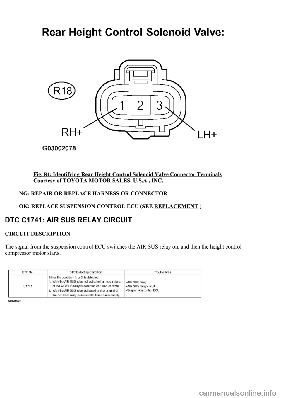
<0029004c004a00110003001b0017001d0003002c0047004800510057004c0049005c004c0051004a000300350048004400550003002b0048004c004a004b00570003002600520051005700550052004f000300360052004f004800510052004c0047000300
390044004f0059004800030026005200510051004800460057[or Terminals
Courtesy of TOYOTA MOTOR SALES, U.S.A., INC.
NG: REPAIR OR REPLACE HARNESS OR CONNECTOR
OK: REPLACE SUSPENSION CONTROL ECU (SEE REPLACEMENT
)
CIRCUIT DESCRIPTION
The signal from the suspension control ECU switches the AIR SUS relay on, and then the height control
compressor motor starts.
Page 567 of 4500
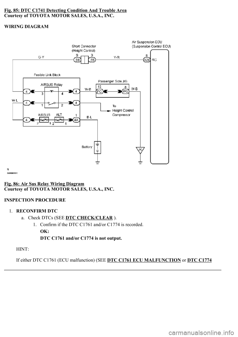
Fig. 85: DTC C1741 Detecting Condition And Trouble Area
Courtesy of TOYOTA MOTOR SALES, U.S.A., INC.
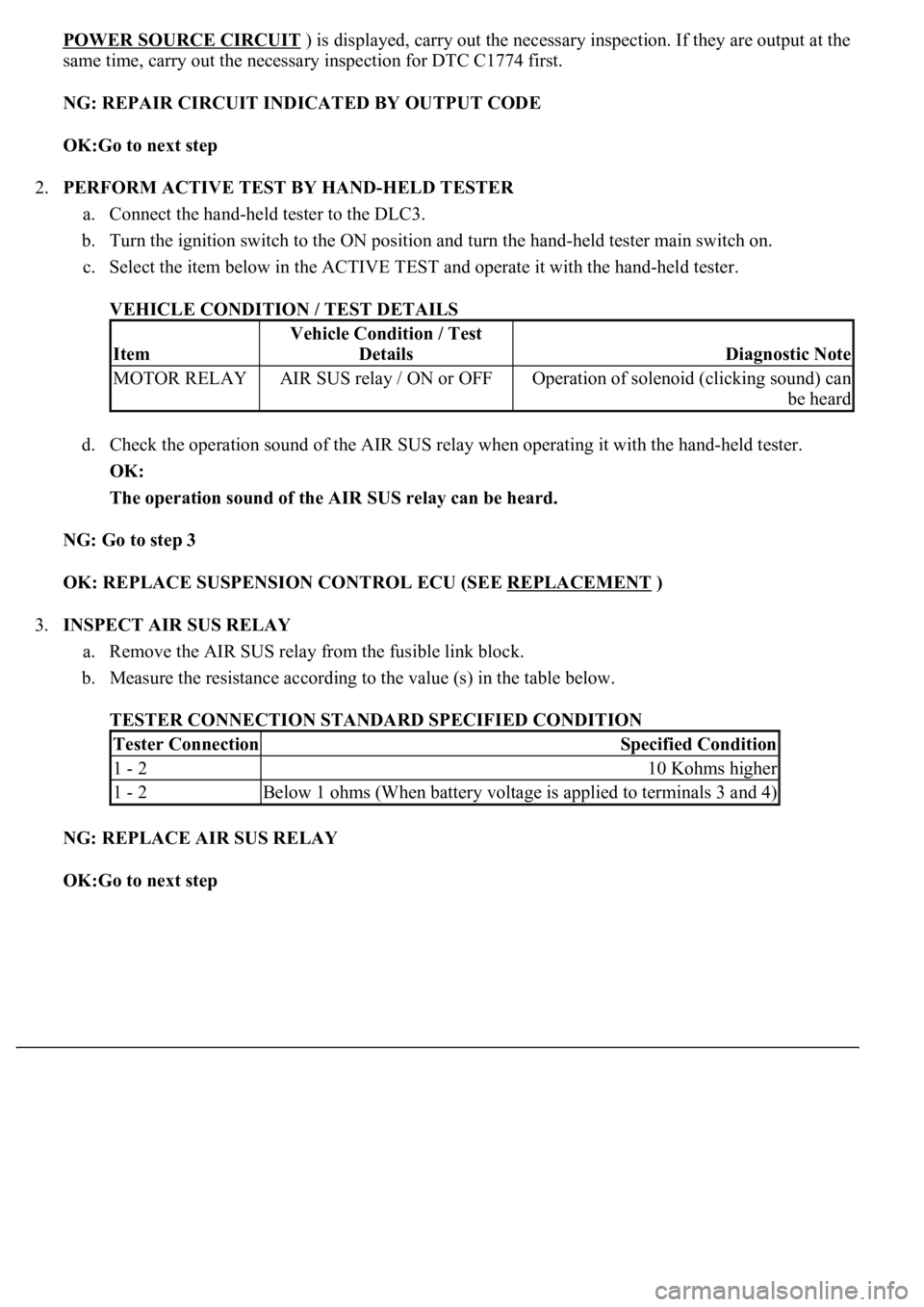
WIRING DIAGRAM
Fig. 86: Air Sus Relay Wiring Diagram
Courtesy of TOYOTA MOTOR SALES, U.S.A., INC.
INSPECTION PROCEDURE
1.RECONFIRM DTC
a. Check DTCs (SEE DTC CHECK/CLEAR
).
1. Confirm if the DTC C1761 and/or C1774 is recorded.
OK:
DTC C1761 and/or C1774 is not output.
HINT:
If either DTC C1761 (ECU malfunction) (SEE DTC C1761 ECU MALFUNCTION
or DTC C1774
Page 568 of 4500
POWER SOURCE CIRCUIT ) is displayed, carry out the necessary inspection. If they are output at the
same time, carry out the necessary inspection for DTC C1774 first.
NG: REPAIR CIRCUIT INDICATED BY OUTPUT CODE
OK:Go to next step
2.PERFORM ACTIVE TEST BY HAND-HELD TESTER
a. Connect the hand-held tester to the DLC3.
b. Turn the ignition switch to the ON position and turn the hand-held tester main switch on.
c. Select the item below in the ACTIVE TEST and operate it with the hand-held tester.
VEHICLE CONDITION / TEST DETAILS
d. Check the operation sound of the AIR SUS relay when operating it with the hand-held tester.
OK:
The operation sound of the AIR SUS relay can be heard.
NG: Go to step 3
OK: REPLACE SUSPENSION CONTROL ECU (SEE REPLACEMENT
)
3.INSPECT AIR SUS RELAY
a. Remove the AIR SUS relay from the fusible link block.
b. Measure the resistance according to the value (s) in the table below.
TESTER CONNECTION STANDARD SPECIFIED CONDITION
NG: REPLACE AIR SUS RELAY
OK:Go to next step
Item
Vehicle Condition / Test
Details
Diagnostic Note
MOTOR RELAYAIR SUS relay / ON or OFFOperation of solenoid (clicking sound) can
be heard
Tester ConnectionSpecified Condition
1 - 210 Kohms higher
1 - 2Below 1 ohms (When battery voltage is applied to terminals 3 and 4)
Page 569 of 4500
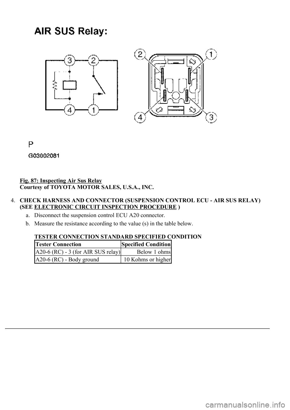
Fig. 87: Inspecting Air Sus Relay
Courtesy of TOYOTA MOTOR SALES, U.S.A., INC.
4.CHECK HARNESS AND CONNECTOR (SUSPENSION CONTROL ECU - AIR SUS RELAY)
(SEE ELECTRONIC CIRCUIT INSPECTION PROCEDURE
)
a. Disconnect the suspension control ECU A20 connector.
b. Measure the resistance according to the value (s) in the table below.
TESTER CONNECTION STANDARD SPECIFIED CONDITION
Tester ConnectionSpecified Condition
A20-6 (RC) - 3 (for AIR SUS relay)Below 1 ohms
A20-6 (RC) - Body ground10 Kohms or higher