relay LEXUS LS430 2003 Factory Service Manual
[x] Cancel search | Manufacturer: LEXUS, Model Year: 2003, Model line: LS430, Model: LEXUS LS430 2003Pages: 4500, PDF Size: 87.45 MB
Page 1077 of 4500
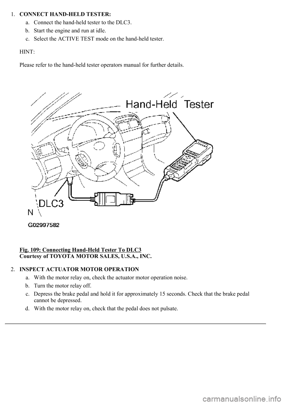
1.CONNECT HAND-HELD TESTER:
a. Connect the hand-held tester to the DLC3.
b. Start the engine and run at idle.
c. Select the ACTIVE TEST mode on the hand-held tester.
HINT:
Please refer to the hand-held tester operators manual for further details.
Fig. 109: Connecting Hand
-Held Tester To DLC3
Courtesy of TOYOTA MOTOR SALES, U.S.A., INC.
2.INSPECT ACTUATOR MOTOR OPERATION
a. With the motor relay on, check the actuator motor operation noise.
b. Turn the motor relay off.
c. Depress the brake pedal and hold it for approximately 15 seconds. Check that the brake pedal
cannot be depressed.
d. With the motor rela
y on, check that the pedal does not pulsate.
Page 1078 of 4500
If the pedal pulsates, replace the motor relay (see DTC C0273/13, C0274/14, C1361/91: OPEN
CIRCUIT IN ABS MOTOR RELAY CIRCUIT, B+ SHORT CIRCUIT IN ABS MOTOR
RELAY CIRCUIT, SHORT CIRCUIT IN ABS MOTOR FAIL SAFE RELAY CIRCUIT ).
e. Turn the motor relay off and release the brake pedal.
3.INSPECT RIGHT FRONT WHEEL OPERATION
a. With the brake pedal depressed, perform the following operations.
b. Turn the SFRH and SFRR solenoids on simultaneously, and check that the pedal cannot be
depressed.
c. Turn the SFRH and SFRR solenoids off simultaneously, and check that the pedal can be depressed.
If the pedal cannot be depressed, replace the ABS & TRACTION ACTUATOR ASSY.
d. Turn the motor relay on, and check that the pedal returns.
e. Turn the motor relay off and release the brake pedal.
4.INSPECT OTHER WHEEL OPERATION
a. Using the same procedure, check the solenoids of the other wheels.
HINT:
Left front wheel: SFLH, SFLR
Right rear wheel: SRRH, SRRR
Left rear wheel: SRLH, SRLR
5.CLEAR DTC (SEE DIAGNOSIS SYSTEM
)
Page 1676 of 4500
NG: REPAIR OR REPLACE HARNESS AND CONNECTOR
OK: Go to next step
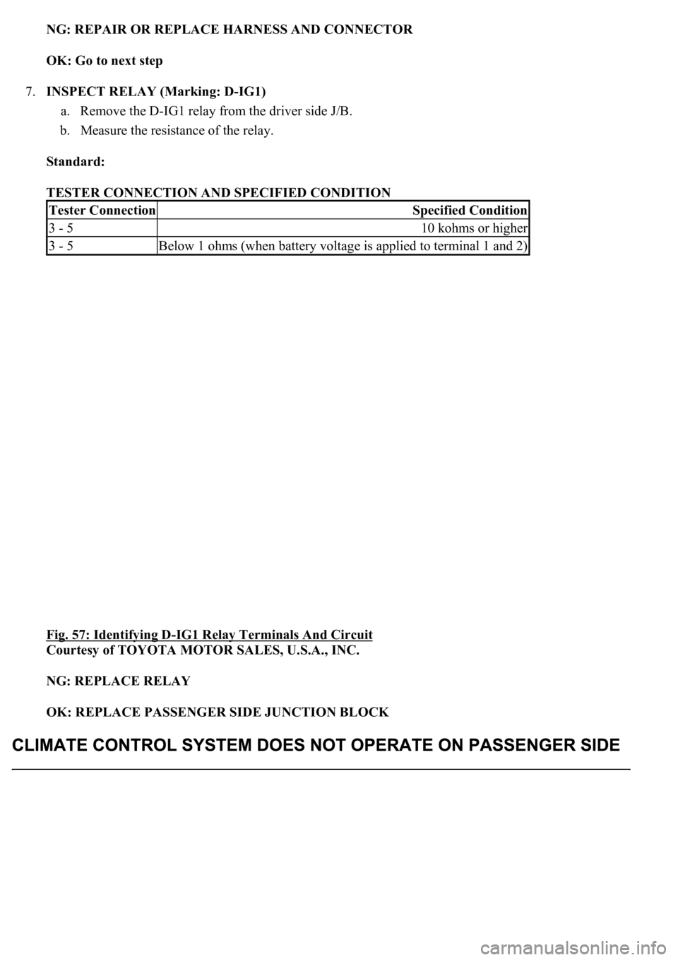
7.INSPECT RELAY (Marking: D-IG1)
a. Remove the D-IG1 relay from the driver side J/B.
b. Measure the resistance of the relay.
Standard:
TESTER CONNECTION AND SPECIFIED CONDITION
Fig. 57: Identifying D
-IG1 Relay Terminals And Circuit
Courtesy of TOYOTA MOTOR SALES, U.S.A., INC.
NG: REPLACE RELAY
OK: REPLACE PASSENGER SIDE JUNCTION BLOCK
Tester ConnectionSpecified Condition
3 - 510 kohms or higher
3 - 5Below 1 ohms (when battery voltage is applied to terminal 1 and 2)
Page 1677 of 4500
CIRCUIT DESCRIPTION
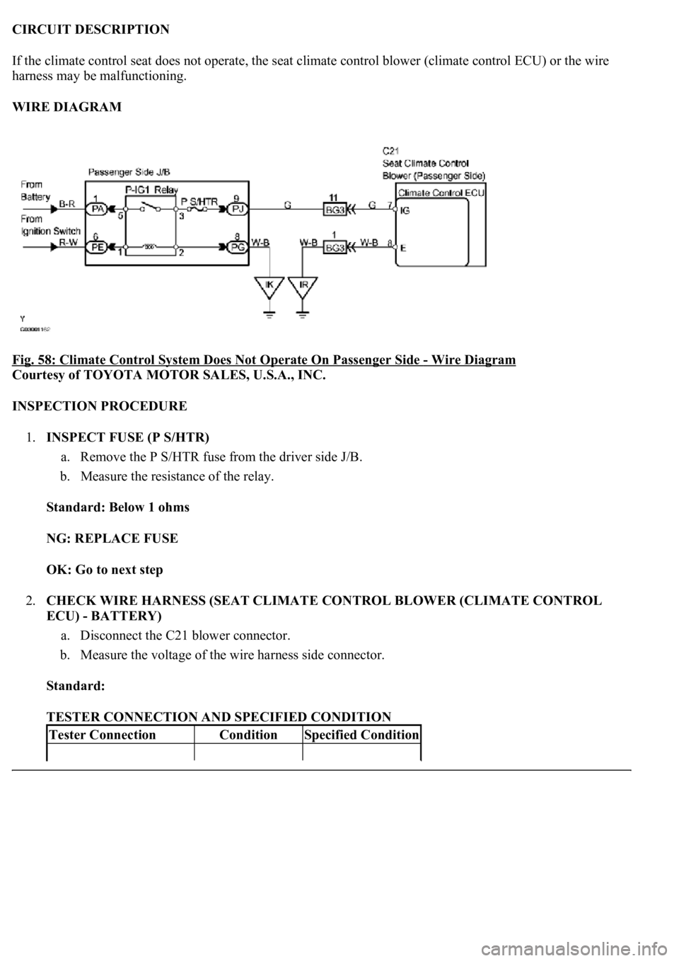
If the climate control seat does not operate, the seat climate control blower (climate control ECU) or the wire
harness may be malfunctioning.
WIRE DIAGRAM
Fig. 58: Climate Control System Does Not Operate On Passenger Side
- Wire Diagram
Courtesy of TOYOTA MOTOR SALES, U.S.A., INC.
INSPECTION PROCEDURE
1.INSPECT FUSE (P S/HTR)
a. Remove the P S/HTR fuse from the driver side J/B.
b. Measure the resistance of the relay.
Standard: Below 1 ohms
NG: REPLACE FUSE
OK: Go to next step
2.CHECK WIRE HARNESS (SEAT CLIMATE CONTROL BLOWER (CLIMATE CONTROL
ECU) - BATTERY)
a. Disconnect the C21 blower connector.
b. Measure the voltage of the wire harness side connector.
Standard:
TESTER CONNECTION AND SPECIFIED CONDITION
Tester ConnectionConditionSpecified Condition
Page 1684 of 4500
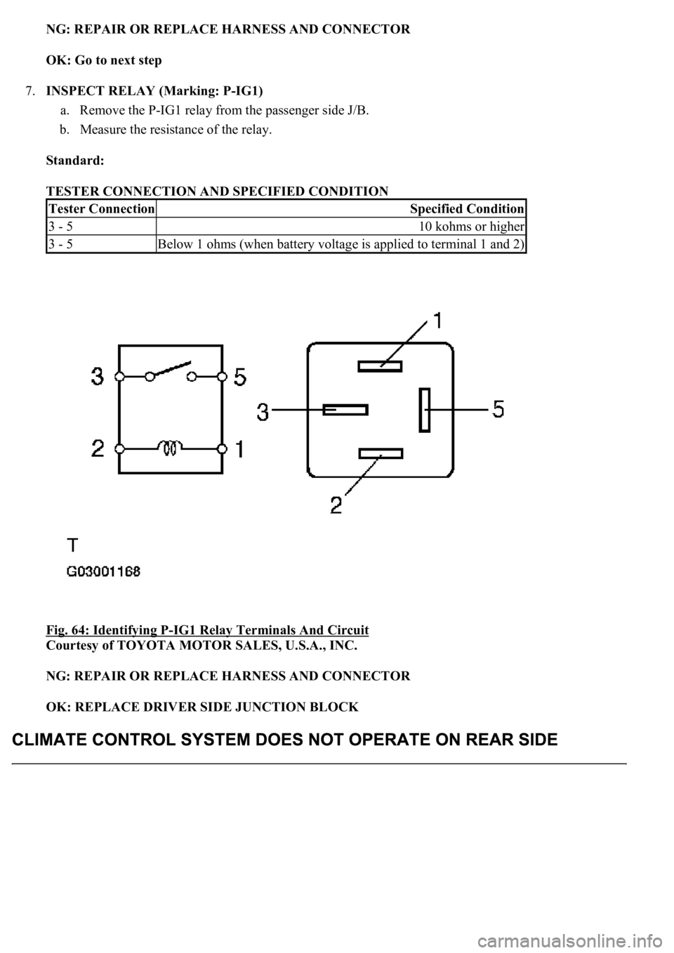
NG: REPAIR OR REPLACE HARNESS AND CONNECTOR
OK: Go to next step
7.INSPECT RELAY (Marking: P-IG1)
a. Remove the P-IG1 relay from the passenger side J/B.
b. Measure the resistance of the relay.
Standard:
TESTER CONNECTION AND SPECIFIED CONDITION
Fig. 64: Identifying P
-IG1 Relay Terminals And Circuit
Courtesy of TOYOTA MOTOR SALES, U.S.A., INC.
NG: REPAIR OR REPLACE HARNESS AND CONNECTOR
OK: REPLACE DRIVER SIDE JUNCTION BLOCK
Tester ConnectionSpecified Condition
3 - 510 kohms or higher
3 - 5Below 1 ohms (when battery voltage is applied to terminal 1 and 2)
Page 1686 of 4500
1.INSPECT FUSE (RR S/HTR)
a. Remove the RR S/HTR fuse from the luggage room J/B.
b. Measure the resistance of the relay.
Standard: Below 1 ohms
NG: REPLACE FUSE
OK: Go to next step
2.CHECK WIRE HARNESS (SEAT CLIMATE CONTROL BLOWER (CLIMATE CONTROL
ECU) - BATTERY)
a. Disconnect the C27 or C29 blower connector.
b. Measure the voltage of the wire harness side connector.
Standard:
Rear LH
TESTER CONNECTION AND SPECIFIED CONDITION
Rear RH
TESTER CONNECTION AND SPECIFIED CONDITION - REAR RH
Tester ConnectionConditionSpecified Condition
C27-10 (IG) - Body groundIgnition switch ON10 to 14 V
Tester ConnectionConditionSpecified Condition
C29-10 (IG) - Body groundIgnition switch ON10 to 14 V
Page 1693 of 4500
Fig. 71: Identifying LA Luggage Room J/B Connector Terminals
Courtesy of TOYOTA MOTOR SALES, U.S.A., INC.
NG: REPAIR OR REPLACE HARNESS AND CONNECTOR
OK: Go to next step
8.INSPECT RELAY (Marking: L-IG1)
a. Remove the L-IG1 relay from the luggage room J/B.
b. Measure the resistance of the relay.
Standard:
Tester ConnectionSpecified Condition
LA-5 - Body groundBelow 1 ohms
Page 1694 of 4500
TESTER CONNECTION AND SPECIFIED CONDITION
Fig. 72: Identifying L
-IG1 Relay Terminals And Circuit
Courtesy of TOYOTA MOTOR SALES, U.S.A., INC.
NG: REPLACE RELAY
OK: Go to next step
9.CHECK WIRE HARNESS (LUGGAGE ROOM J/B ECU - BATTERY AND BODY GROUND)
a. Disconnect the L14 J/B ECU connector.
b. Measure the voltage of the wire harness side connector.
Standard:
TESTER CONNECTION AND SPECIFIED CONDITION
Tester ConnectionSpecified Condition
3 - 510 kohms or higher
3 - 5Below 1ohms (when battery voltage is applied to terminal 1 and 2)
Tester ConnectionConditionSpecified Condition
L14-8 (IG (O)) - Body groundIgnition switch OFF10 to 14 V
L14-14 (P-GND) - Body groundAlwaysBelow 1ohms
Page 1756 of 4500
Once calibration is completed, it is not necessary to perform the above procedures unless the magnetic
field strength is drastically changed.
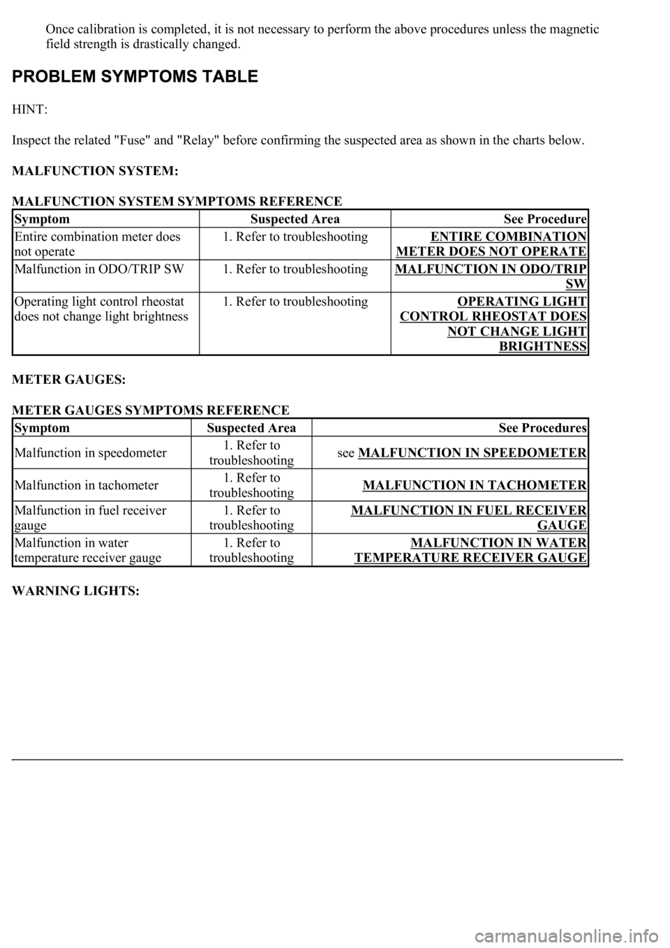
HINT:
Inspect the related "Fuse" and "Relay" before confirming the suspected area as shown in the charts below.
MALFUNCTION SYSTEM:
MALFUNCTION SYSTEM SYMPTOMS REFERENCE
METER GAUGES:
METER GAUGES SYMPTOMS REFERENCE
WARNING LIGHTS:
SymptomSuspected AreaSee Procedure
Entire combination meter does
not operate1. Refer to troubleshootingENTIRE COMBINATION
METER DOES NOT OPERATE
Malfunction in ODO/TRIP SW1. Refer to troubleshootingMALFUNCTION IN ODO/TRIP
SW
Operating light control rheostat
does not change light brightness1. Refer to troubleshootingOPERATING LIGHT
CONTROL RHEOSTAT DOES
NOT CHANGE LIGHT
BRIGHTNESS
SymptomSuspected AreaSee Procedures
Malfunction in speedometer1. Refer to
troubleshootingsee MALFUNCTION IN SPEEDOMETER
Malfunction in tachometer1. Refer to
troubleshootingMALFUNCTION IN TACHOMETER
Malfunction in fuel receiver
gauge1. Refer to
troubleshootingMALFUNCTION IN FUEL RECEIVER
GAUGE
Malfunction in water
temperature receiver gauge1. Refer to
troubleshootingMALFUNCTION IN WATER
TEMPERATURE RECEIVER GAUGE
Page 1859 of 4500
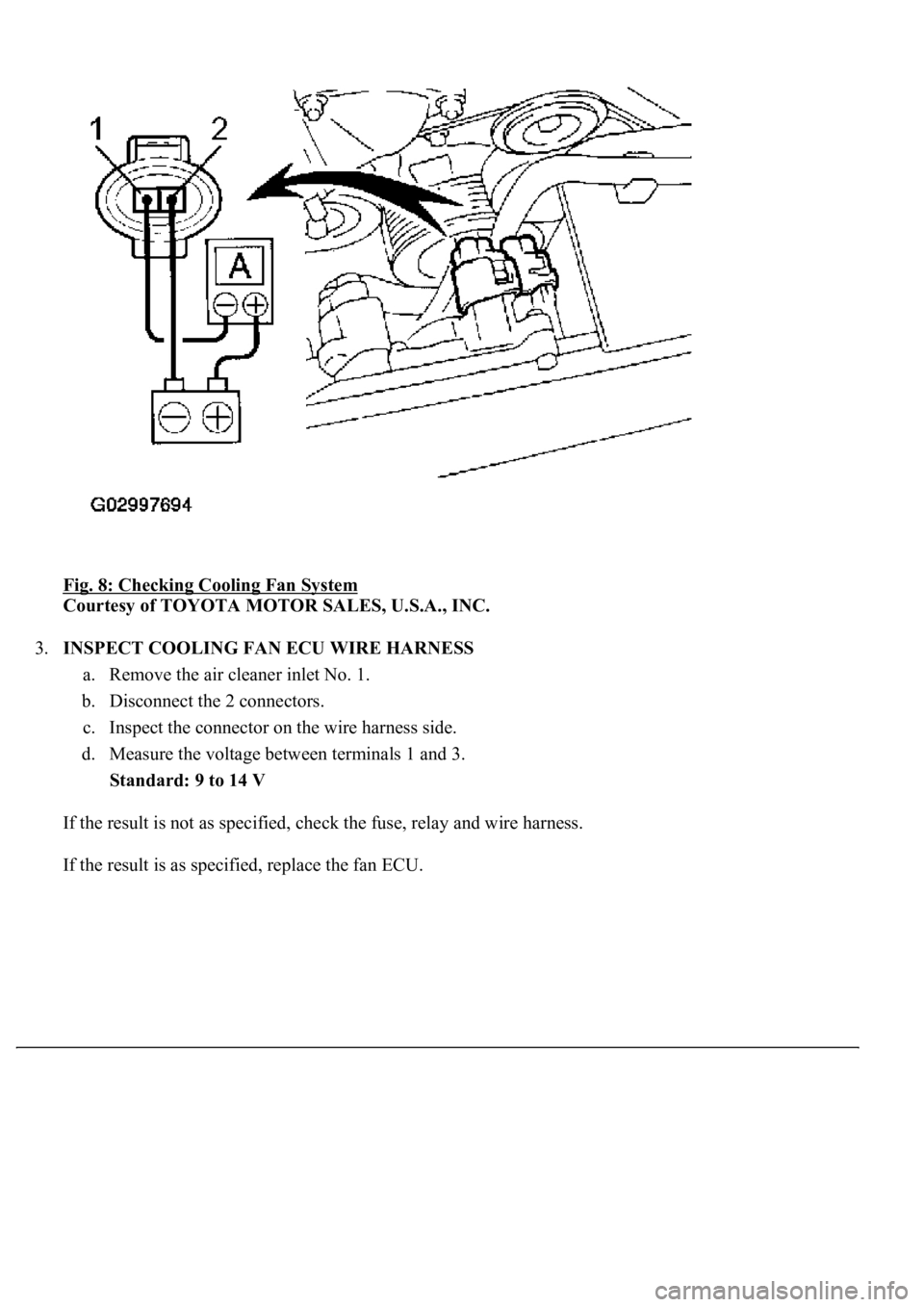
Fig. 8: Checking Cooling Fan System
Courtesy of TOYOTA MOTOR SALES, U.S.A., INC.
3.INSPECT COOLING FAN ECU WIRE HARNESS
a. Remove the air cleaner inlet No. 1.
b. Disconnect the 2 connectors.
c. Inspect the connector on the wire harness side.
d. Measure the voltage between terminals 1 and 3.
Standard: 9 to 14 V
If the result is not as specified, check the fuse, relay and wire harness.
If the result is as specified, replace the fan ECU.