battery LEXUS LS430 2003 Factory Owner's Guide
[x] Cancel search | Manufacturer: LEXUS, Model Year: 2003, Model line: LS430, Model: LEXUS LS430 2003Pages: 4500, PDF Size: 87.45 MB
Page 427 of 4500
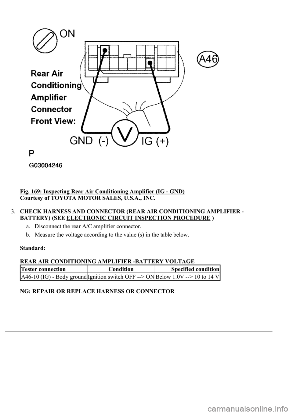
Fig. 169: Inspecting Rear Air Conditioning Amplifier (IG - GND)
Courtesy of TOYOTA MOTOR SALES, U.S.A., INC.
3.CHECK HARNESS AND CONNECTOR (REAR AIR CONDITIONING AMPLIFIER -
BATTERY) (SEE ELECTRONIC CIRCUIT INSPECTION PROCEDURE
)
a. Disconnect the rear A/C amplifier connector.
b. Measure the voltage according to the value (s) in the table below.
Standard:
REAR AIR CONDITIONING AMPLIFIER -BATTERY VOLTAGE
NG: REPAIR OR REPLACE HARNESS OR CONNECTOR
Tester connectionConditionSpecified condition
A46-10 (IG) - Body groundIgnition switch OFF --> ONBelow 1.0V --> 10 to 14 V
Page 428 of 4500
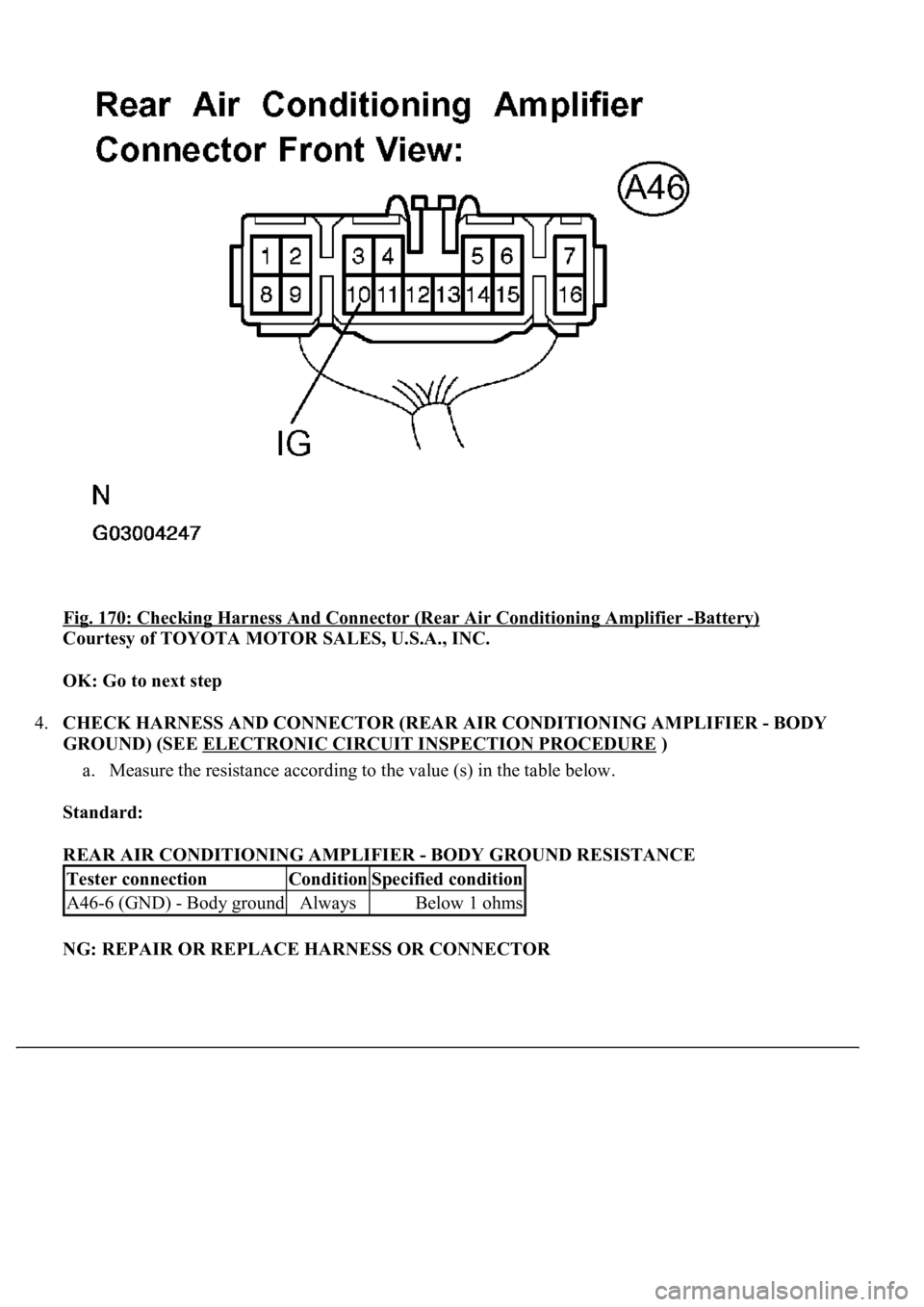
Fig. 170: Checking Harness And Connector (Rear Air Conditioning Amplifier -Battery)
Courtesy of TOYOTA MOTOR SALES, U.S.A., INC.
OK: Go to next step
4.CHECK HARNESS AND CONNECTOR (REAR AIR CONDITIONING AMPLIFIER - BODY
GROUND) (SEE ELECTRONIC CIRCUIT INSPECTION PROCEDURE
)
a. Measure the resistance according to the value (s) in the table below.
Standard:
REAR AIR CONDITIONING AMPLIFIER - BODY GROUND RESISTANCE
NG: REPAIR OR REPLACE HARNESS OR CONNECTOR
Tester connectionConditionSpecified condition
A46-6 (GND) - Body groundAlwaysBelow 1 ohms
Page 444 of 4500
Courtesy of TOYOTA MOTOR SALES, U.S.A., INC.
INSPECTION PROCEDURE
a. PERFORM ACTUATOR CHECK
a. Warm up the engine.
b. Set the actuator check mode (see ACTUATOR CHECK
).
c. Press the driver temperature up switch, and change to STEP operation.
d. Press the driver temperature up switch, and check the air flow by hand.
ACTUATOR INSPECTION
A/P: Air purifier
OK: Exhaust damper position changes in accordance with each display code.
NG: Go to STEP 2
OK: PROCEED TO NEXT CIRCUIT INSPECTION SHOWN IN PROBLEM SYMPTOMS
TABLE
b.INSPECT EXHAUST SERVOMOTOR
a. Remove the exhaust servomotor.
b. Connect the positive (+) lead from the battery to terminal 7 and negative (-) lead to terminal 1, then
check that the lever turns to the "ROO" position smoothly.
c. Connect the positive (+) lead from the battery to terminal 7 and negative (-) lead to terminal 3, then
check that the lever turns to the "DIO" position smoothly.
d. Connect the positive (+) lead from the battery to terminal 7 and negative (-) lead to terminal 5, then
check that the lever turns to the "EXO" position smoothl
y.
Display CodeRear A/C ModeExhaust DamperCondition
0OFFExhaust positionNo air comes out
1LOA/PDiffusion positionNo air comes out
2HIA/PDiffusion positionNo air comes out
3 to 4HI A/CCool positionCool air comes out
5LOA/CCool positionCool air comes out
6 to 9OFFCool positionNo air comes out
Page 452 of 4500
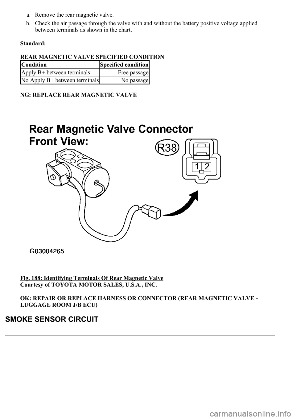
a. Remove the rear magnetic valve.
b. Check the air passage through the valve with and without the battery positive voltage applied
between terminals as shown in the chart.
Standard:
REAR MAGNETIC VALVE SPECIFIED CONDITION
NG: REPLACE REAR MAGNETIC VALVE
Fig. 188: Identifying Terminals Of Rear Magnetic Valve
Courtesy of TOYOTA MOTOR SALES, U.S.A., INC.
OK: REPAIR OR REPLACE HARNESS OR CONNECTOR (REAR MAGNETIC VALVE -
LUGGAGE ROOM J/B ECU)
ConditionSpecified condition
Apply B+ between terminalsFree passage
No Apply B+ between terminalsNo passage
Page 456 of 4500
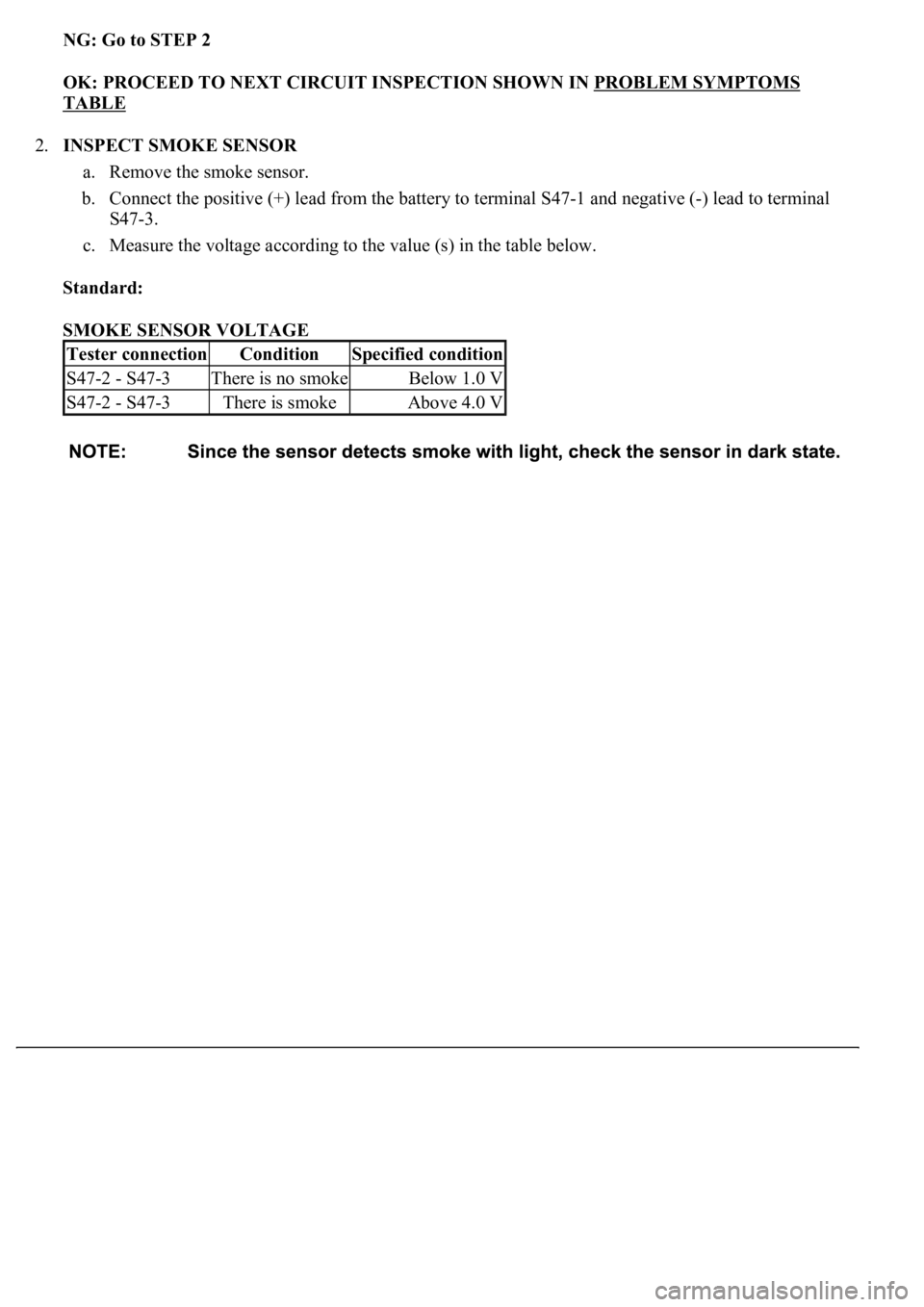
NG: Go to STEP 2
OK: PROCEED TO NEXT CIRCUIT INSPECTION SHOWN IN PROBLEM SYMPTOMS
TABLE
2.INSPECT SMOKE SENSOR
a. Remove the smoke sensor.
b. Connect the positive (+) lead from the battery to terminal S47-1 and negative (-) lead to terminal
S47-3.
c. Measure the voltage according to the value (s) in the table below.
Standard:
SMOKE SENSOR VOLTAGE
Tester connectionConditionSpecified condition
S47-2 - S47-3There is no smokeBelow 1.0 V
S47-2 - S47-3There is smokeAbove 4.0 V
Page 458 of 4500
Courtesy of TOYOTA MOTOR SALES, U.S.A., INC.
NG: REPLACE SMOKE SENSOR
OK: Go to next step
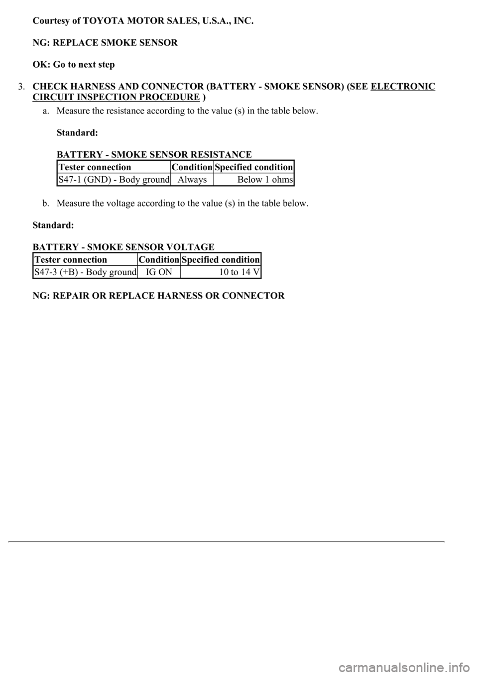
3.CHECK HARNESS AND CONNECTOR (BATTERY - SMOKE SENSOR) (SEE ELECTRONIC
CIRCUIT INSPECTION PROCEDURE )
a. Measure the resistance according to the value (s) in the table below.
Standard:
BATTERY - SMOKE SENSOR RESISTANCE
b. Measure the voltage according to the value (s) in the table below.
Standard:
BATTERY - SMOKE SENSOR VOLTAGE
NG: REPAIR OR REPLACE HARNESS OR CONNECTOR
Tester connectionConditionSpecified condition
S47-1 (GND) - Body groundAlwaysBelow 1 ohms
Tester connectionConditionSpecified condition
S47-3 (+B) - Body groundIG ON10 to 14 V
Page 469 of 4500
If the vehicle is raised with its engine running, connect terminals OPB and CG of the DLC3 to stop
the vehicle height control operation of the suspension control ECU.
Do not operate the steering wheel if there is no air in the pneumatic cylinder.
HINT:
The pneumatic cylinder could be damaged if twisted without air in the cylinder.
In the case of lifting down the vehicle without air in the cylinder, make sure all the pipes are securely
connected.
HINT:
The pneumatic cylinder could be damaged if any pipe is disconnected while lifting down the vehicle.
Do not apply battery voltage to the compressor motor for more than 60 seconds to prevent damage to the
motor.
HINT:
When it is necessary to perform the operation by charging the battery for more than 60 seconds, for example
height recovery without air in the cylinder, proceed to the operation as follows: after 60 seconds have passed,
turn the ignition switch off once, and then turn the ignition switch to the ON position again for commencement
of operation.
Page 480 of 4500
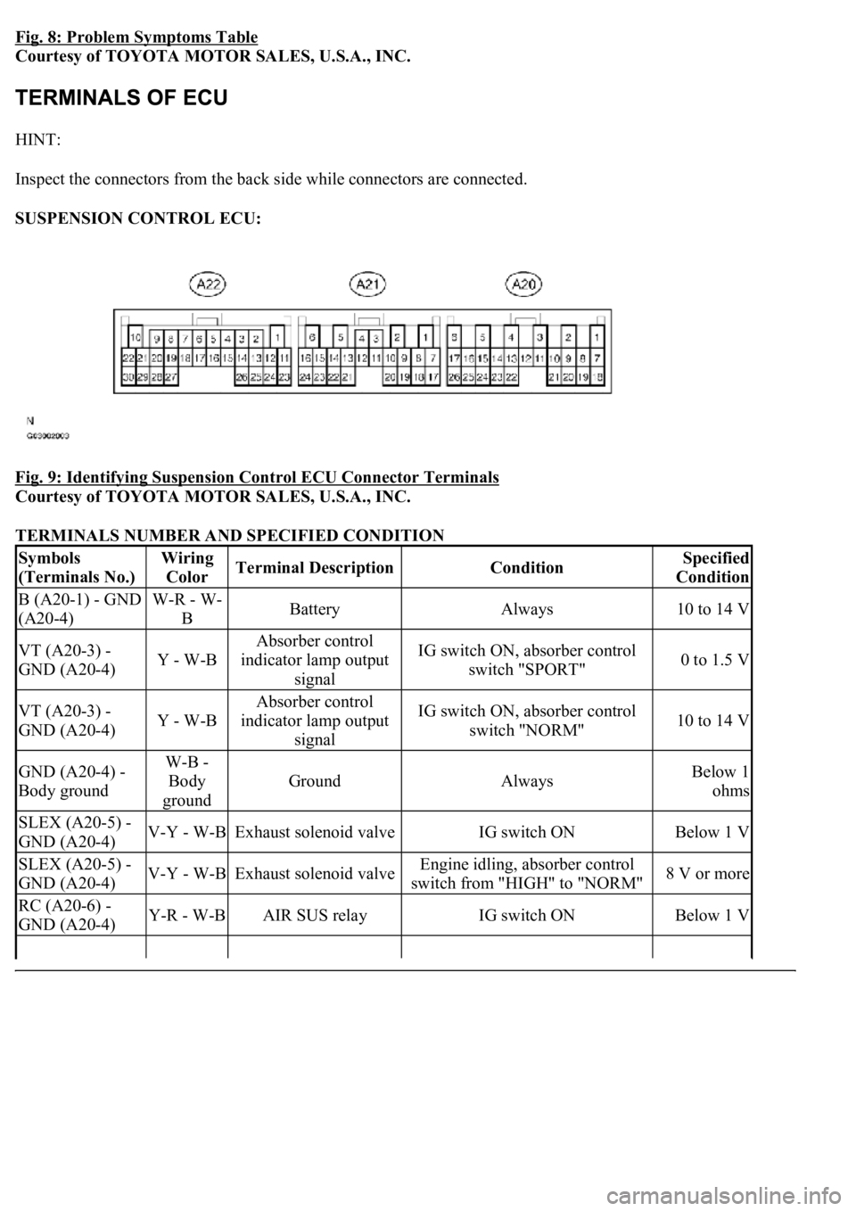
Fig. 8: Problem Symptoms Table
Courtesy of TOYOTA MOTOR SALES, U.S.A., INC.
HINT:
Inspect the connectors from the back side while connectors are connected.
SUSPENSION CONTROL ECU:
Fig. 9: Identifying Suspension Control ECU Connector Terminals
Courtesy of TOYOTA MOTOR SALES, U.S.A., INC.
TERMINALS NUMBER AND SPECIFIED CONDITION
Symbols
(Terminals No.)Wiring
ColorTerminal DescriptionConditionSpecified
Condition
B (A20-1) - GND
(A20-4)W-R - W-
BBatteryAlways10 to 14 V
VT (A20-3) -
GND (A20-4)Y - W-B
Absorber control
indicator lamp output
signalIG switch ON, absorber control
switch "SPORT"0 to 1.5 V
VT (A20-3) -
GND (A20-4)Y - W-B
Absorber control
indicator lamp output
signalIG switch ON, absorber control
switch "NORM"10 to 14 V
GND (A20-4) -
Body groundW-B -
Body
ground
GroundAlwaysBelow 1
ohms
SLEX (A20-5) -
GND (A20-4)V-Y - W-BExhaust solenoid valveIG switch ONBelow 1 V
SLEX (A20-5) -
GND (A20-4)V-Y - W-BExhaust solenoid valveEngine idling, absorber control
switch from "HIGH" to "NORM"8 V or more
RC (A20-6) -
GND (A20-4)Y-R - W-BAIR SUS relayIG switch ONBelow 1 V
Page 483 of 4500
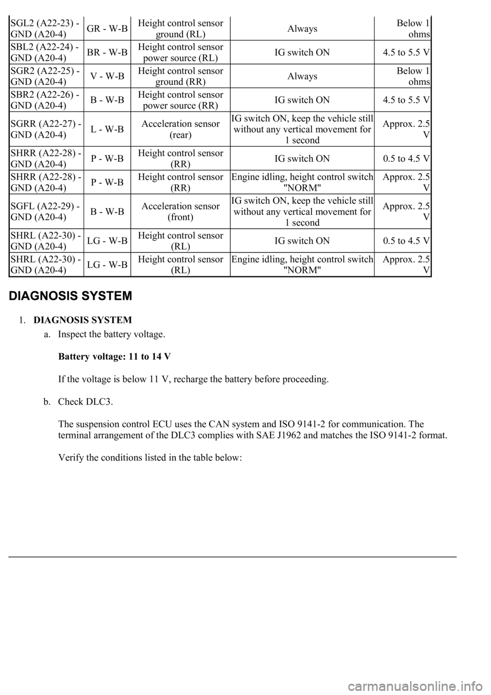
1.DIAGNOSIS SYSTEM
a. Inspect the battery voltage.
Battery voltage: 11 to 14 V
If the voltage is below 11 V, recharge the battery before proceeding.
b. Check DLC3.
The suspension control ECU uses the CAN system and ISO 9141-2 for communication. The
terminal arrangement of the DLC3 complies with SAE J1962 and matches the ISO 9141-2 format.
Verify the conditions listed in the table below:
SGL2 (A22-23) -
GND (A20-4)GR - W-BHeight control sensor
ground (RL)AlwaysBelow 1
ohms
SBL2 (A22-24) -
GND (A20-4)BR - W-BHeight control sensor
power source (RL)IG switch ON4.5 to 5.5 V
SGR2 (A22-25) -
GND (A20-4)V - W-BHeight control sensor
ground (RR)AlwaysBelow 1
ohms
SBR2 (A22-26) -
GND (A20-4)B - W-BHeight control sensor
power source (RR)IG switch ON4.5 to 5.5 V
SGRR (A22-27) -
GND (A20-4)L - W-BAcceleration sensor
(rear)IG switch ON, keep the vehicle still
without any vertical movement for
1 secondApprox. 2.5
V
SHRR (A22-28) -
GND (A20-4)P - W-BHeight control sensor
(RR)IG switch ON0.5 to 4.5 V
SHRR (A22-28) -
GND (A20-4)P - W-BHeight control sensor
(RR)Engine idling, height control switch
"NORM"Approx. 2.5
V
SGFL (A22-29) -
GND (A20-4)B - W-BAcceleration sensor
(front)IG switch ON, keep the vehicle still
without any vertical movement for
1 secondApprox. 2.5
V
SHRL (A22-30) -
GND (A20-4)LG - W-BHeight control sensor
(RL)IG switch ON0.5 to 4.5 V
SHRL (A22-30) -
GND (A20-4)LG - W-BHeight control sensor
(RL)Engine idling, height control switch
"NORM"Approx. 2.5
V
Page 484 of 4500
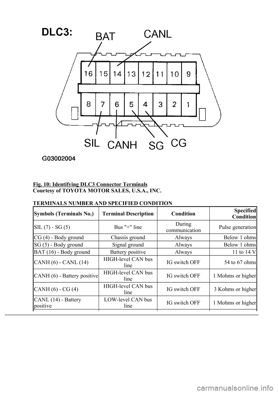
Fig. 10: Identifying DLC3 Connector Terminals
Courtesy of TOYOTA MOTOR SALES, U.S.A., INC.
TERMINALS NUMBER AND SPECIFIED CONDITION
Symbols (Terminals No.)Terminal DescriptionConditionSpecified
Condition
SIL (7) - SG (5)Bus "+" lineDuring
communicationPulse generation
CG (4) - Body groundChassis groundAlwaysBelow 1 ohms
SG (5) - Body groundSignal groundAlwaysBelow 1 ohms
BAT (16) - Body groundBattery positiveAlways11 to 14 V
CANH (6) - CANL (14)HIGH-level CAN bus
lineIG switch OFF54 to 67 ohms
CANH (6) - Battery positiveHIGH-level CAN bus
lineIG switch OFF1 Mohms or higher
CANH (6) - CG (4)HIGH-level CAN bus
lineIG switch OFF3 Kohms or higher
CANL (14) - Battery
positiveLOW-level CAN bus
lineIG switch OFF1 Mohms or higher