height LEXUS LS430 2003 Factory Service Manual
[x] Cancel search | Manufacturer: LEXUS, Model Year: 2003, Model line: LS430, Model: LEXUS LS430 2003Pages: 4500, PDF Size: 87.45 MB
Page 524 of 4500
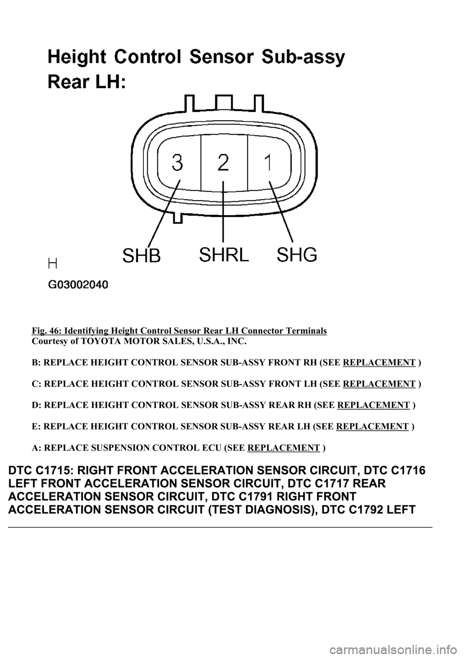
Fig. 46: Identifying Height Control Sensor Rear LH Connector Terminals
Courtesy of TOYOTA MOTOR SALES, U.S.A., INC.
B: REPLACE HEIGHT CONTROL SENSOR SUB-ASSY FRONT RH (SEE REPLACEMENT
)
C: REPLACE HEIGHT CONTROL SENSOR SUB-ASSY FRONT LH (SEE REPLACEMENT
)
D: REPLACE HEIGHT CONTROL SENSOR SUB-ASSY REAR RH (SEE REPLACEMENT
)
E: REPLACE HEIGHT CONTROL SENSOR SUB-ASSY REAR LH (SEE REPLACEMENT
)
A: REPLACE SUSPENSION CONTROL ECU (SEE REPLACEMENT
)
Page 527 of 4500
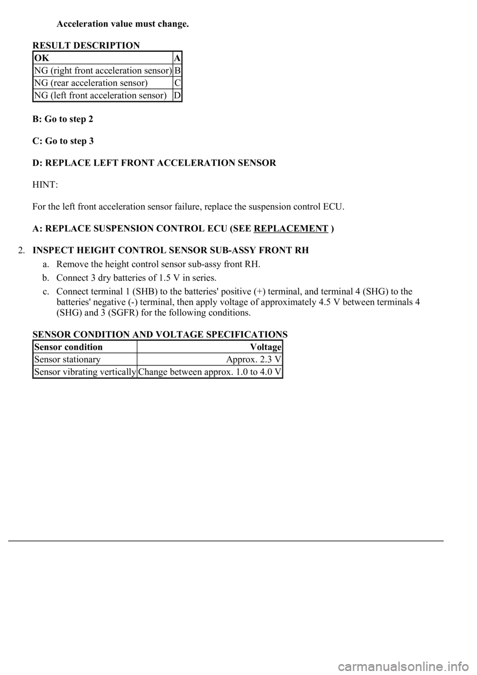
Acceleration value must change.
RESULT DESCRIPTION
B: Go to step 2
C: Go to step 3
D: REPLACE LEFT FRONT ACCELERATION SENSOR
HINT:
For the left front acceleration sensor failure, replace the suspension control ECU.
A: REPLACE SUSPENSION CONTROL ECU (SEE REPLACEMENT
)
2.INSPECT HEIGHT CONTROL SENSOR SUB-ASSY FRONT RH
a. Remove the height control sensor sub-assy front RH.
b. Connect 3 dry batteries of 1.5 V in series.
c. Connect terminal 1 (SHB) to the batteries' positive (+) terminal, and terminal 4 (SHG) to the
batteries' negative (-) terminal, then apply voltage of approximately 4.5 V between terminals 4
(SHG) and 3 (SGFR) for the following conditions.
SENSOR CONDITION AND VOLTAGE SPECIFICATIONS
OKA
NG (right front acceleration sensor)B
NG (rear acceleration sensor)C
NG (left front acceleration sensor)D
Sensor conditionVoltage
Sensor stationaryApprox. 2.3 V
Sensor vibrating verticallyChange between approx. 1.0 to 4.0 V
Page 528 of 4500
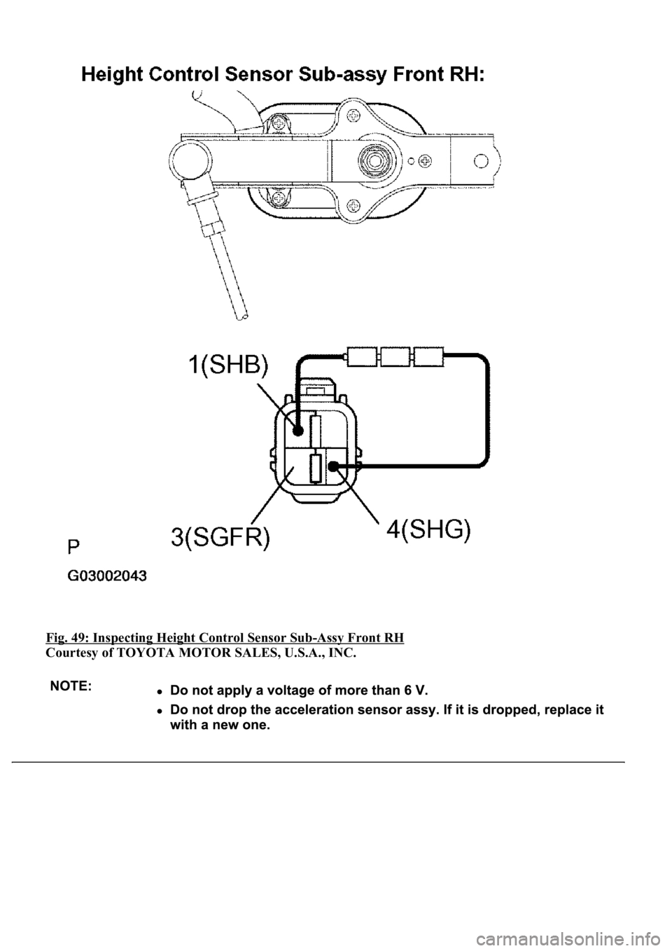
Fig. 49: Inspecting Height Control Sensor Sub-Assy Front RH
Courtesy of TOYOTA MOTOR SALES, U.S.A., INC.
Page 529 of 4500
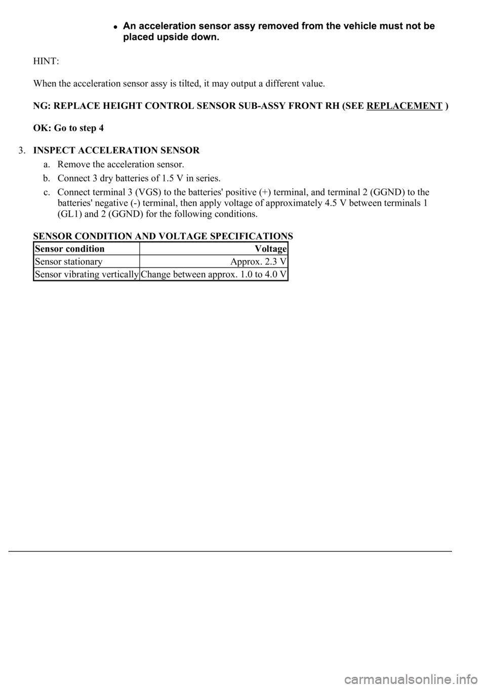
HINT:
When the acceleration sensor assy is tilted, it may output a different value.
NG: REPLACE HEIGHT CONTROL SENSOR SUB-ASSY FRONT RH (SEE REPLACEMENT
)
OK: Go to step 4
3.INSPECT ACCELERATION SENSOR
a. Remove the acceleration sensor.
b. Connect 3 dry batteries of 1.5 V in series.
c. Connect terminal 3 (VGS) to the batteries' positive (+) terminal, and terminal 2 (GGND) to the
batteries' negative (-) terminal, then apply voltage of approximately 4.5 V between terminals 1
(GL1) and 2 (GGND) for the following conditions.
SENSOR CONDITION AND VOLTAGE SPECIFICATIONS
Sensor conditionVoltage
Sensor stationaryApprox. 2.3 V
Sensor vibrating verticallyChange between approx. 1.0 to 4.0 V
Page 532 of 4500
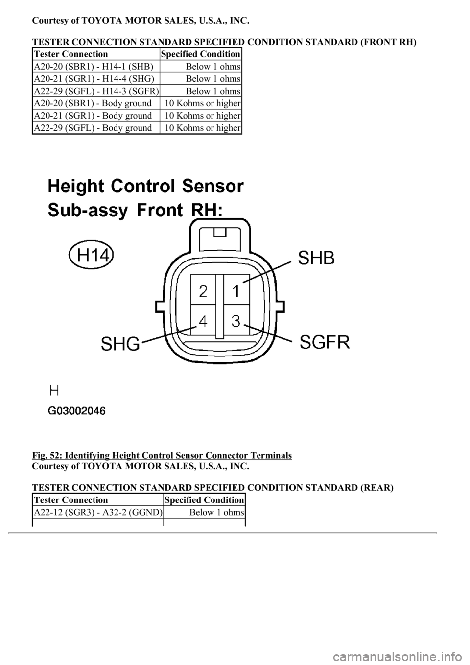
Courtesy of TOYOTA MOTOR SALES, U.S.A., INC.
TESTER CONNECTION STANDARD SPECIFIED CONDITION STANDARD (FRONT RH)
Fig. 52: Identifying Height Control Sensor Connector Terminals
Courtesy of TOYOTA MOTOR SALES, U.S.A., INC.
TESTER CONNECTION STANDARD SPECIFIED CONDITION STANDARD (REAR)
Tester ConnectionSpecified Condition
A20-20 (SBR1) - H14-1 (SHB)Below 1 ohms
A20-21 (SGR1) - H14-4 (SHG)Below 1 ohms
A22-29 (SGFL) - H14-3 (SGFR)Below 1 ohms
A20-20 (SBR1) - Body ground10 Kohms or higher
A20-21 (SGR1) - Body ground10 Kohms or higher
A22-29 (SGFL) - Body ground10 Kohms or higher
Tester ConnectionSpecified Condition
A22-12 (SGR3) - A32-2 (GGND)Below 1 ohms
Page 533 of 4500
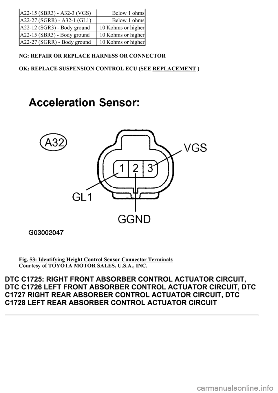
NG: REPAIR OR REPLACE HARNESS OR CONNECTOR
OK: REPLACE SUSPENSION CONTROL ECU (SEE REPLACEMENT
)
Fig. 53: Identifying Height Control Sensor Connector Terminals
Courtesy of TOYOTA MOTOR SALES, U.S.A., INC.
A22-15 (SBR3) - A32-3 (VGS)Below 1 ohms
A22-27 (SGRR) - A32-1 (GL1)Below 1 ohms
A22-12 (SGR3) - Body ground10 Kohms or higher
A22-15 (SBR3) - Body ground10 Kohms or higher
A22-27 (SGRR) - Body ground10 Kohms or higher
Page 550 of 4500
OK:Go to next step
2.INSPECT EXHAUST SOLENOID VALVE
a. Disconnect the exhaust solenoid valve connector.
b. Measure the resistance according to the value (s) in the table below.
TESTER CONNECTION STANDARD SPECIFIED CONDITION
c. Connect terminal 1 (SLEX) to the battery positive (+) terminal, and terminal 2 (GND) to the battery
negative (-) terminal.
d. Check the operating sound of the exhaust solenoid valve.
OK:
It should make an operating sound (click).
HINT:
When a malfunction is found in the exhaust solenoid valve, replace the height control compressor assy.
NG: REPLACE HEIGHT CONTROL COMPRESSOR ASSY (SEE REPLACEMENT
)
OK:Go to next step
Tester ConnectionSpecified Condition
1 (SLEX) - 2 (GND)10 to 14 ohms
Page 555 of 4500
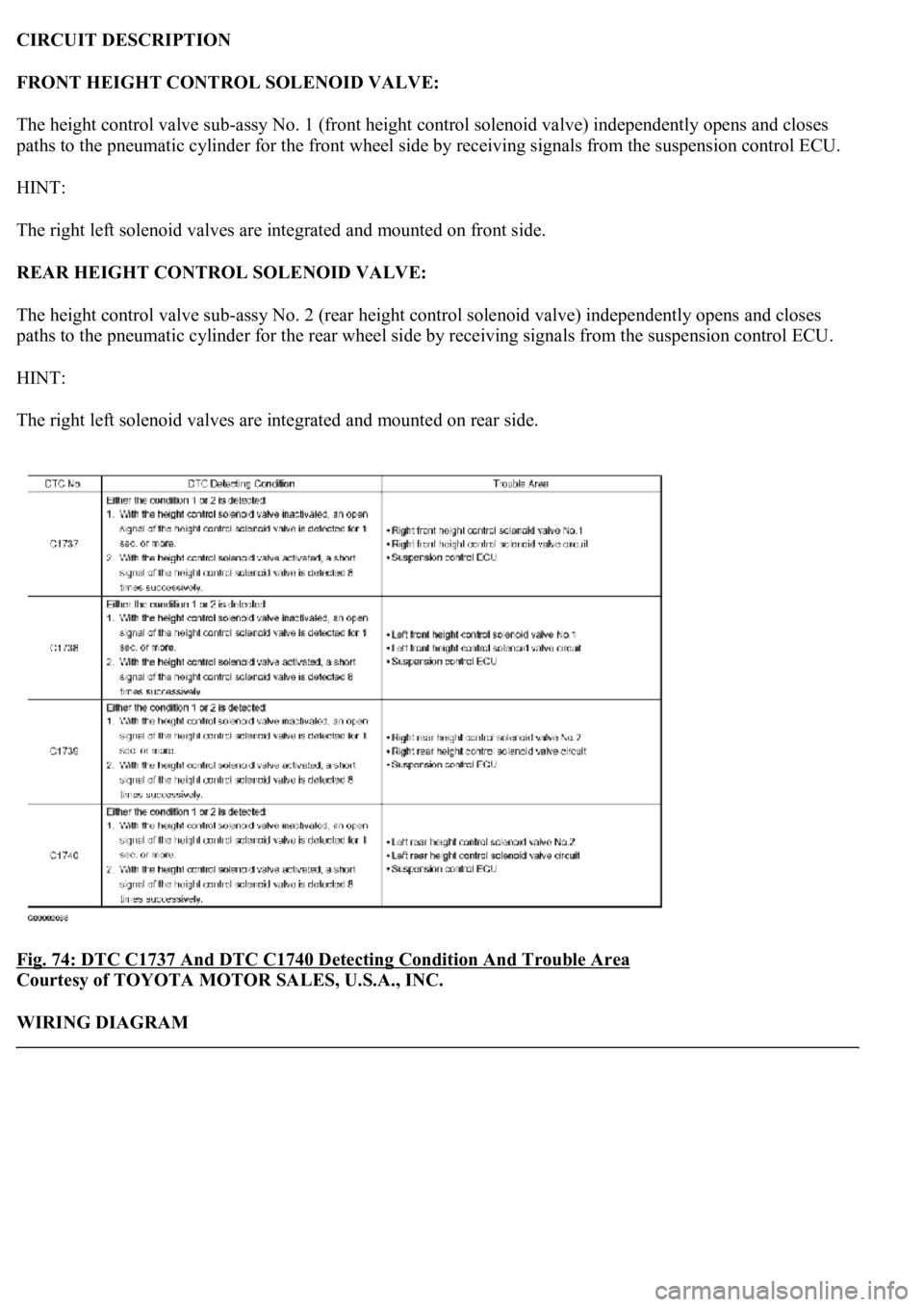
CIRCUIT DESCRIPTION
FRONT HEIGHT CONTROL SOLENOID VALVE:
The height control valve sub-assy No. 1 (front height control solenoid valve) independently opens and closes
paths to the pneumatic cylinder for the front wheel side by receiving signals from the suspension control ECU.
HINT:
The right left solenoid valves are integrated and mounted on front side.
REAR HEIGHT CONTROL SOLENOID VALVE:
The height control valve sub-assy No. 2 (rear height control solenoid valve) independently opens and closes
paths to the pneumatic cylinder for the rear wheel side by receiving signals from the suspension control ECU.
HINT:
The right left solenoid valves are integrated and mounted on rear side.
Fig. 74: DTC C1737 And DTC C1740 Detecting Condition And Trouble Area
Courtesy of TOYOTA MOTOR SALES, U.S.A., INC.
WIRING DIAGRAM
Page 556 of 4500
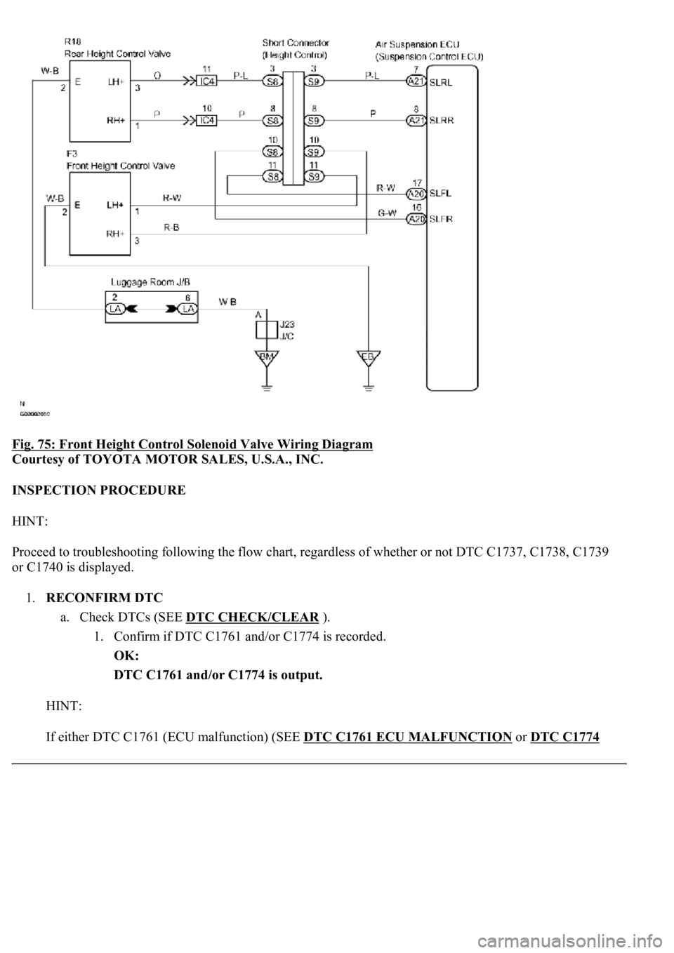
Fig. 75: Front Height Control Solenoid Valve Wiring Diagram
Courtesy of TOYOTA MOTOR SALES, U.S.A., INC.
INSPECTION PROCEDURE
HINT:
Proceed to troubleshooting following the flow chart, regardless of whether or not DTC C1737, C1738, C1739
or C1740 is displayed.
1.RECONFIRM DTC
a. Check DTCs (SEE DTC CHECK/CLEAR
).
1. Confirm if DTC C1761 and/or C1774 is recorded.
OK:
DTC C1761 and/or C1774 is output.
HINT:
If either DTC C1761 (ECU malfunction) (SEE DTC C1761 ECU MALFUNCTION
or DTC C1774
Page 557 of 4500
POWER SOURCE CIRCUIT ) is displayed, carry out the necessary inspection. If they are output at the
same time, carry out the necessary inspection for DTC C1774 first.
NG: REPAIR CIRCUIT INDICATED BY OUTPUT CODE
OK:Go to next step
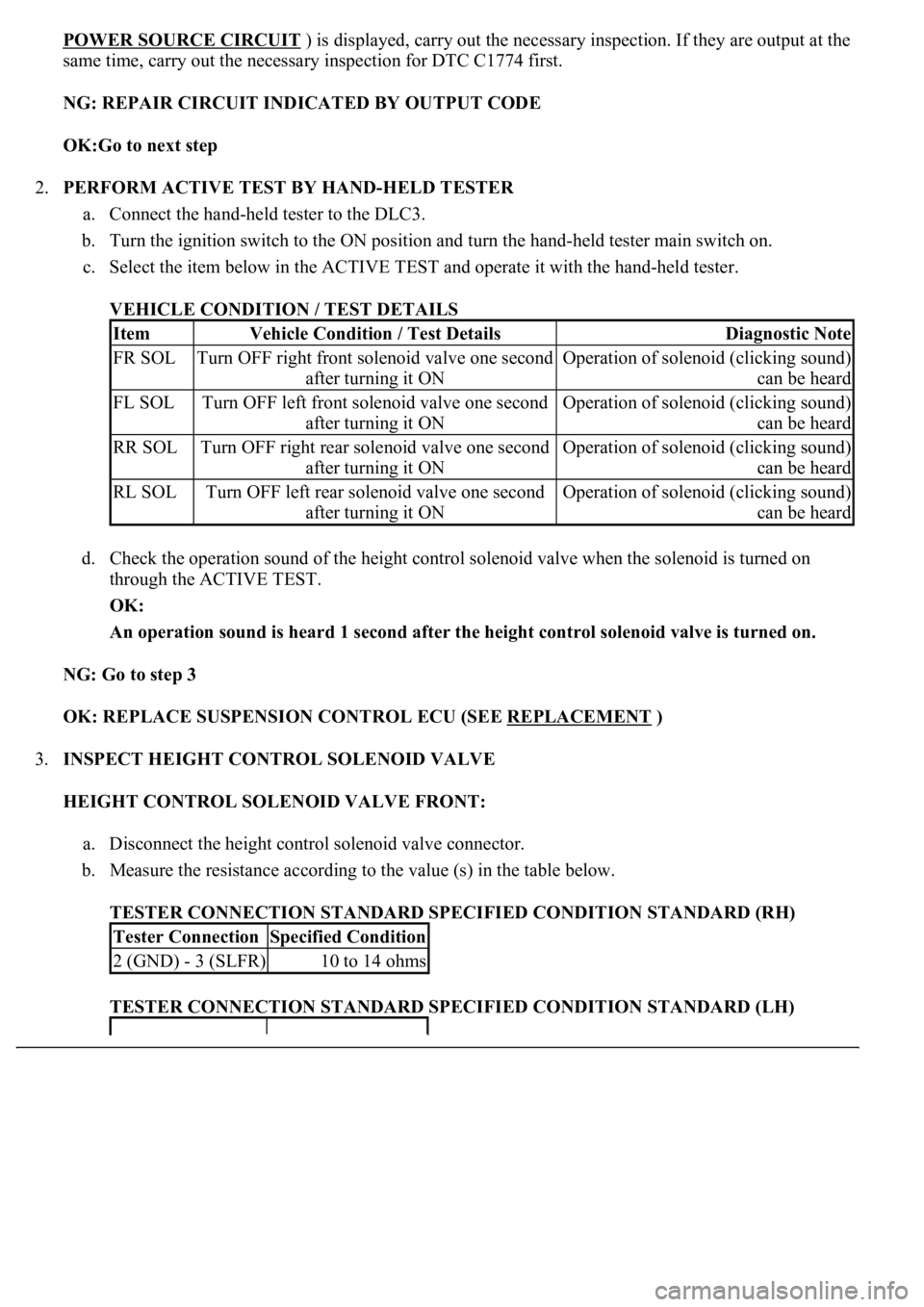
2.PERFORM ACTIVE TEST BY HAND-HELD TESTER
a. Connect the hand-held tester to the DLC3.
b. Turn the ignition switch to the ON position and turn the hand-held tester main switch on.
c. Select the item below in the ACTIVE TEST and operate it with the hand-held tester.
VEHICLE CONDITION / TEST DETAILS
d. Check the operation sound of the height control solenoid valve when the solenoid is turned on
through the ACTIVE TEST.
OK:
An operation sound is heard 1 second after the height control solenoid valve is turned on.
NG: Go to step 3
OK: REPLACE SUSPENSION CONTROL ECU (SEE REPLACEMENT
)
3.INSPECT HEIGHT CONTROL SOLENOID VALVE
HEIGHT CONTROL SOLENOID VALVE FRONT:
a. Disconnect the height control solenoid valve connector.
b. Measure the resistance according to the value (s) in the table below.
TESTER CONNECTION STANDARD SPECIFIED CONDITION STANDARD (RH)
TESTER CONNECTION STANDARD SPECIFIED CONDITION STANDARD (LH)
ItemVehicle Condition / Test DetailsDiagnostic Note
FR SOLTurn OFF right front solenoid valve one second
after turning it ONOperation of solenoid (clicking sound)
can be heard
FL SOLTurn OFF left front solenoid valve one second
after turning it ONOperation of solenoid (clicking sound)
can be heard
RR SOLTurn OFF right rear solenoid valve one second
after turning it ONOperation of solenoid (clicking sound)
can be heard
RL SOLTurn OFF left rear solenoid valve one second
after turning it ONOperation of solenoid (clicking sound)
can be heard
Tester ConnectionSpecified Condition
2 (GND) - 3 (SLFR)10 to 14 ohms