LEXUS LS430 2003 Factory Manual Online
LS430 2003
LEXUS
LEXUS
https://www.carmanualsonline.info/img/36/57050/w960_57050-0.png
LEXUS LS430 2003 Factory Manual Online
Page 596 of 4500
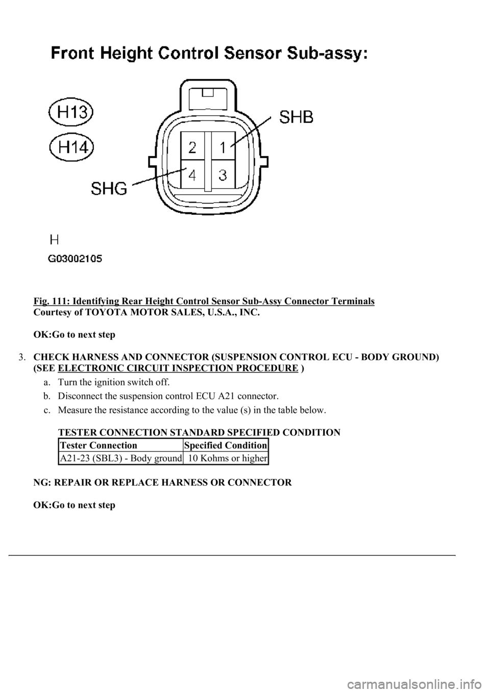
Fig. 111: Identifying Rear Height Control Sensor Sub-Assy Connector Terminals
Courtesy of TOYOTA MOTOR SALES, U.S.A., INC.
OK:Go to next step
3.CHECK HARNESS AND CONNECTOR (SUSPENSION CONTROL ECU - BODY GROUND)
(SEE ELECTRONIC CIRCUIT INSPECTION PROCEDURE
)
a. Turn the ignition switch off.
b. Disconnect the suspension control ECU A21 connector.
c. Measure the resistance according to the value (s) in the table below.
TESTER CONNECTION STANDARD SPECIFIED CONDITION
NG: REPAIR OR REPLACE HARNESS OR CONNECTOR
OK:Go to next step
Tester ConnectionSpecified Condition
A21-23 (SBL3) - Body ground10 Kohms or higher
Page 598 of 4500
Fig. 113: Identifying Suspension Control ECU Connector Terminals
Courtesy of TOYOTA MOTOR SALES, U.S.A., INC.
NG: CHECK POWER SOURCE CIRCUIT (SEE DTC C1774 POWER SOURCE CIRCUIT
)
OK: REPLACE SUSPENSION CONTROL ECU (SEE REPLACEMENT
)
CIRCUIT DESCRIPTION
When the ignition switch is turned to the ON position, the D-IG1 relay is activated and battery voltage is
applied to terminal B of the suspension control ECU. When the ignition switch is turned off, the D-IG1 relay is
de-energized and the power source is cut off.
This power source energizes the suspension control actuator, height control solenoid valve, D-IG1 relay, each
IC and sensor.
Page 610 of 4500
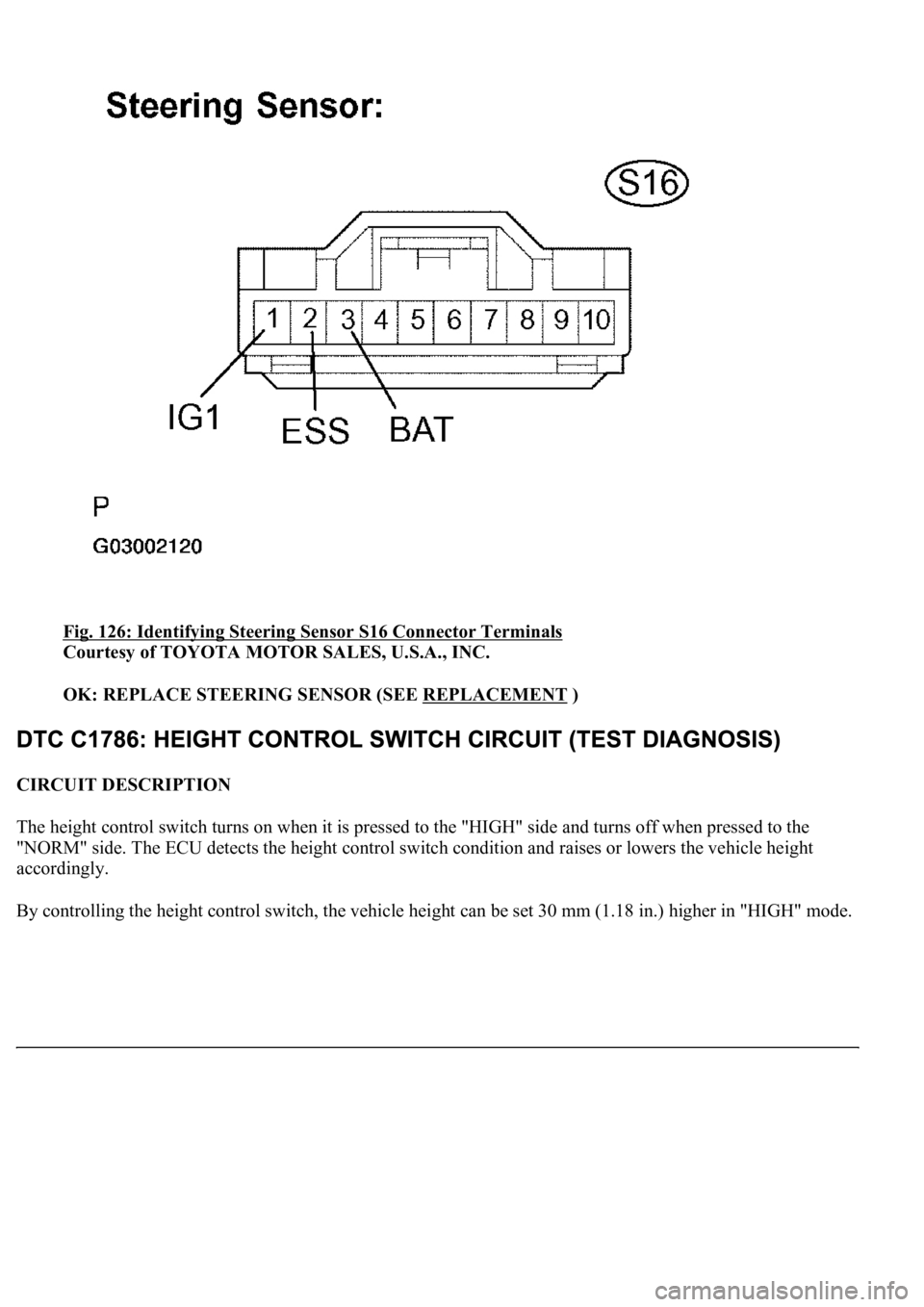
Fig. 126: Identifying Steering Sensor S16 Connector Terminals
Courtesy of TOYOTA MOTOR SALES, U.S.A., INC.
OK: REPLACE STEERING SENSOR (SEE REPLACEMENT
)
CIRCUIT DESCRIPTION
The height control switch turns on when it is pressed to the "HIGH" side and turns off when pressed to the
"NORM" side. The ECU detects the height control switch condition and raises or lowers the vehicle height
accordingly.
B
y controlling the height control switch, the vehicle height can be set 30 mm (1.18 in.) higher in "HIGH" mode.
Page 611 of 4500
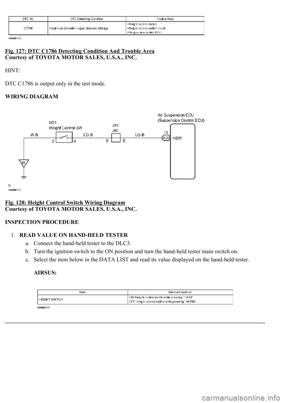
Fig. 127: DTC C1786 Detecting Condition And Trouble Area
Courtesy of TOYOTA MOTOR SALES, U.S.A., INC.
HINT:
DTC C1786 is output only in the test mode.
WIRING DIAGRAM
Fig. 128: Height Control Switch Wiring Diagram
Courtesy of TOYOTA MOTOR SALES, U.S.A., INC.
INSPECTION PROCEDURE
1.READ VALUE ON HAND-HELD TESTER
a. Connect the hand-held tester to the DLC3.
b. Turn the ignition switch to the ON position and turn the hand-held tester main switch on.
c. Select the item below in the DATA LIST and read its value displayed on the hand-held tester.
AIRSUS:
Page 612 of 4500
Fig. 129: Data List Value - Air sus
Courtesy of TOYOTA MOTOR SALES, U.S.A., INC.
d. Check that the value displayed on the hand-held tester changes by pressing the height control
switch "HIGH" or "NORM" button.
OK:
Height control switch value changes.
NG: Go to step 2
OK: REPLACE SUSPENSION CONTROL ECU (SEE REPLACEMENT
)
2.INSPECT HEIGHT CONTROL SWITCH
a. Disconnect the height control switch connector.
b. Measure the resistance according to the value (s) in the table below.
TESTER CONNECTION STANDARD SPECIFIED CONDITION
NG: REPLACE HEIGHT CONTROL SWITCH
OK:Go to next step
Switch ConditionTester ConnectionSpecified Condition
"HIGH"2 (IGH) - 4 (HSW)Below 1 ohms
"NORM"2 (IGH) - 4 (HSW)10 Kohms or higher
Page 613 of 4500
Fig. 130: Identifying Height Control Switch Connector Terminals
Courtesy of TOYOTA MOTOR SALES, U.S.A., INC.
3.CHECK HARNESS AND CONNECTOR (SUSPENSION CONTROL ECU - HEIGHT
CONTROL SWITCH) (SEE ELECTRONIC CIRCUIT INSPECTION PROCEDURE
)
a. Disconnect the suspension control ECU A20 connector.
b. Measure the resistance according to the value (s) in the table below.
TESTER CONNECTION STANDARD SPECIFIED CONDITION
Tester ConnectionSpecified Condition
A20-15 (HSW) - H21-4 (HSW)Below 1 ohms
A20-15 (HSW) - Body ground10 Kohms or higher
Page 615 of 4500
Fig. 132: Identifying Height Control Switch Connector Terminals
Courtesy of TOYOTA MOTOR SALES, U.S.A., INC.
NG: REPAIR OR REPLACE HARNESS OR CONNECTOR
OK:Go to next step
4.CHECK HARNESS AND CONNECTOR (HEIGHT CONTROL SWITCH - BODY GROUND)
(SEE ELECTRONIC CIRCUIT INSPECTION PROCEDURE
)
a. Measure the resistance according to the value (s) in the table below.
TESTER CONNECTION STANDARD SPECIFIED CONDITION
Tester ConnectionSpecified Condition
H21-2 (IGN) - Body groundBelow 1 ohms
Page 616 of 4500
Fig. 133: Identifying Height Control Switch Connector Terminals
Courtesy of TOYOTA MOTOR SALES, U.S.A., INC.
NG: REPAIR OR REPLACE HARNESS OR CONNECTOR
OK: REPLACE SUSPENSION CONTROL ECU (SEE REPLACEMENT
)
CIRCUIT DESCRIPTION
The absorber control switch is used to select the attenuation modes of the shock absorber. 2 levels of
attenuation, "SPORT" and "NORM", are available.
Page 621 of 4500
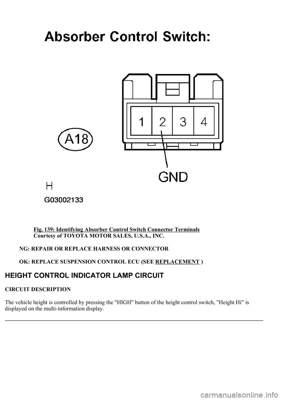
Fig. 139: Identifying Absorber Control Switch Connector Terminals
Courtesy of TOYOTA MOTOR SALES, U.S.A., INC.
NG: REPAIR OR REPLACE HARNESS OR CONNECTOR
OK: REPLACE SUSPENSION CONTROL ECU (SEE REPLACEMENT
)
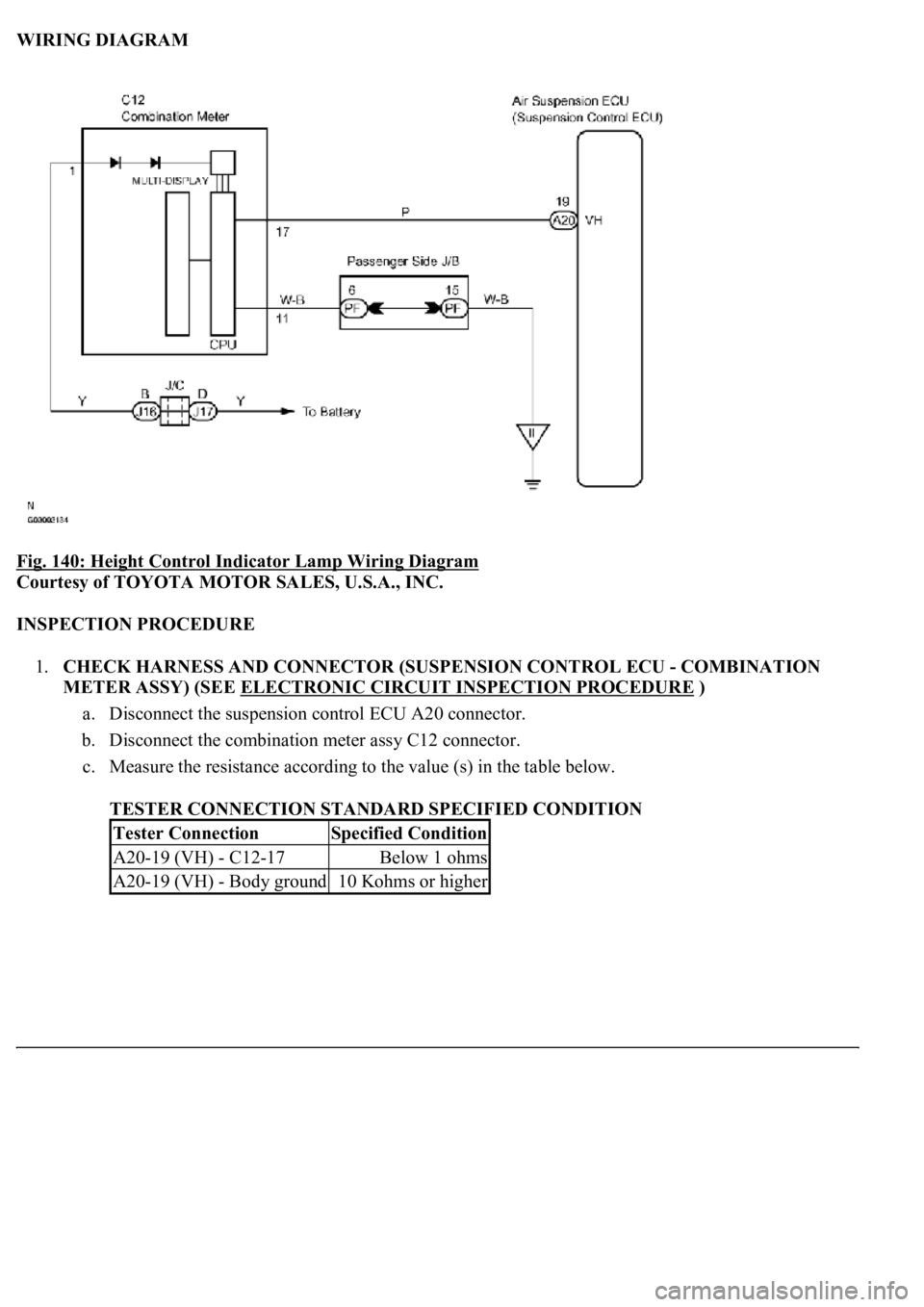
CIRCUIT DESCRIPTION
The vehicle height is controlled by pressing the "HIGH" button of the height control switch, "Height Hi" is
displayed on the multi-information display.
Page 622 of 4500
WIRING DIAGRAM
Fig. 140: Height Control Indicator Lamp Wiring Diagram
Courtesy of TOYOTA MOTOR SALES, U.S.A., INC.
INSPECTION PROCEDURE
1.CHECK HARNESS AND CONNECTOR (SUSPENSION CONTROL ECU - COMBINATION
METER ASSY) (SEE ELECTRONIC CIRCUIT INSPECTION PROCEDURE
)
a. Disconnect the suspension control ECU A20 connector.
b. Disconnect the combination meter assy C12 connector.
c. Measure the resistance according to the value (s) in the table below.
TESTER CONNECTION STANDARD SPECIFIED CONDITION
Tester ConnectionSpecified Condition
A20-19 (VH) - C12-17Below 1 ohms
A20-19 (VH) - Body ground10 Kohms or higher