LEXUS LS430 2003 Factory Manual PDF
LS430 2003
LEXUS
LEXUS
https://www.carmanualsonline.info/img/36/57050/w960_57050-0.png
LEXUS LS430 2003 Factory Manual PDF
Page 537 of 4500
Fig. 56: Identifying Absorber Control Actuator LH Connector Terminals
Courtesy of TOYOTA MOTOR SALES, U.S.A., INC.
TESTER CONNECTION STANDARD SPECIFIED CONDITION STANDARD (FRONT LH)
Tester ConnectionSpecified Condition
1 (FBL+) - 3 (GND)12.0 to 12.8 ohms
2 (FAL+) - 3 (GND)12.0 to 12.8 ohms
3 (GND) - 4 (FBL-)12.0 to 12.8 ohms
3 (GND) - 5 (FAL-)12.0 to 12.8 ohms
Page 538 of 4500
Fig. 57: Identifying Absorber Control Actuator RH Connector Terminals
Courtesy of TOYOTA MOTOR SALES, U.S.A., INC.
TESTER CONNECTION STANDARD SPECIFIED CONDITION STANDARD (REAR RH)
Tester ConnectionSpecified Condition
1 (RBR+) - 3 (ERR)12.0 to 12.8 ohms
2 (RAR+) - 3 (ERR)12.0 to 12.8 ohms
3 (ERR) - 4 (RBR-)12.0 to 12.8 ohms
3 (ERR) - 5 (RAR-)12.0 to 12.8 ohms
Page 539 of 4500
Fig. 58: Identifying Absorber Control Actuator Rear RH Connector Terminals
Courtesy of TOYOTA MOTOR SALES, U.S.A., INC.
TESTER CONNECTION STANDARD SPECIFIED CONDITION STANDARD (REAR LH)
Tester ConnectionSpecified Condition
1 (RBL+) - 3 (ERL)12.0 to 12.8 ohms
2 (RAL+) - 3 (ERL)12.0 to 12.8 ohms
3 (ERL) - 4 (RBL-)12.0 to 12.8 ohms
3 (ERL) - 5 (RAL-)12.0 to 12.8 ohms
Page 540 of 4500
Fig. 59: Identifying Absorber Control Actuator Rear LH Connector Terminals
Courtesy of TOYOTA MOTOR SALES, U.S.A., INC.
NG: REPLACE ABSORBER CONTROL ACTUATOR
OK:Go to next step
3.CHECK HARNESS AND CONNECTOR (ABSORBER CONTROL ACTUATOR - SUSPENSION
CONTROL ECU) (SEE ELECTRONIC CIRCUIT INSPECTION PROCEDURE
)
a. Disconnect the air suspension ECU A21 or A22 connector.
b. Measure the resistance according to the value (s) in the table below.
TESTER CONNECTION STANDARD SPECIFIED CONDITION STANDARD (FRONT RH)
Tester ConnectionSpecified Condition
A21-1 (FAR+) - S6-2 (FAR+)Below 1 ohms
A21-2 (FAR-) - S6-5 (FAR-)Below 1 ohms
A21-3 (FBR+) - S6-1 (FBR+)Below 1 ohms
A21-4 (FBR-) - S6-4 (FBR-)Below 1 ohms
A21-1 (FAR+) - Body ground10 Kohms or higher
Page 542 of 4500
Fig. 61: Identifying Absorber Control Actuator Front Connector Terminals
Courtesy of TOYOTA MOTOR SALES, U.S.A., INC.
TESTER CONNECTION STANDARD SPECIFIED CONDITION STANDARD (FRONT LH)
Tester ConnectionSpecified Condition
A21-5 (FAL+) - S5-2 (FAL+)Below 1 ohms
A21-6 (FBL+) - S5-1 (FBL+)Below 1 ohms
A21-14 (FAL-) - S5-5 (FAL-)Below 1 ohms
A21-16 (FBL-) - S5-4 (FBL-)Below 1 ohms
A21-5 (FAL+) - Body ground10 Kohms or higher
A21-6 (FBL+) - Body ground10 Kohms or higher
A21-14 (FAL-) - Body ground10 Kohms or higher
A21-16 (FBL-) - Body ground10 Kohms or higher
S5-3 (GND) - Body groundBelow 1 ohms
Page 544 of 4500
Fig. 63: Identifying Absorber Control Actuator Front Connector Terminals
Courtesy of TOYOTA MOTOR SALES, U.S.A., INC.
TESTER CONNECTION STANDARD SPECIFIED CONDITION STANDARD (REAR RH)
Tester ConnectionSpecified Condition
A22-2 (RAR+) - S33-2 (RAR+)Below 1 ohms
A22-3 (RAR-) - S33-5 (RAR-)Below 1 ohms
A22-4 (RBR+) - S33-1 (RBR+)Below 1 ohms
A22-5 (RBR-) - S33-4 (RBR-)Below 1 ohms
A22-2 (RAR+) - Body ground10 Kohms or higher
A22-3 (RAR-) - Body ground10 Kohms or higher
A22-4 (RBR+) - Body ground10 Kohms or higher
A22-5 (RBR-) - Body ground10 Kohms or higher
S33-3 (ERR) - Body groundBelow 1 ohms
Page 546 of 4500
Fig. 65: Identifying Absorber Control Actuator Rear RH Connector Terminals
Courtesy of TOYOTA MOTOR SALES, U.S.A., INC.
TESTER CONNECTION STANDARD SPECIFIED CONDITION STANDARD (REAR LH)
Tester ConnectionSpecified Condition
A22-6 (RAL+) - S32-2 (RAL+)Below 1 ohms
A22-7 (RAL-) S32-5 (RAL-)Below 1 ohms
A22-8 (RBL+) - S32-1 (RBL+)Below 1 ohms
A22-9 (RBL-) - S32-4 (RBL-)Below 1 ohms
A22-6 (RAL+) - Body ground10 Kohms or higher
A22-7 (RAL-) - Body ground10 Kohms or higher
A22-8 (RBL+) - Body ground10 Kohms or higher
A22-9 (RBL-) - Body ground10 Kohms or higher
S32-3 (ERL) - Body groundBelow 1 ohms
Page 551 of 4500
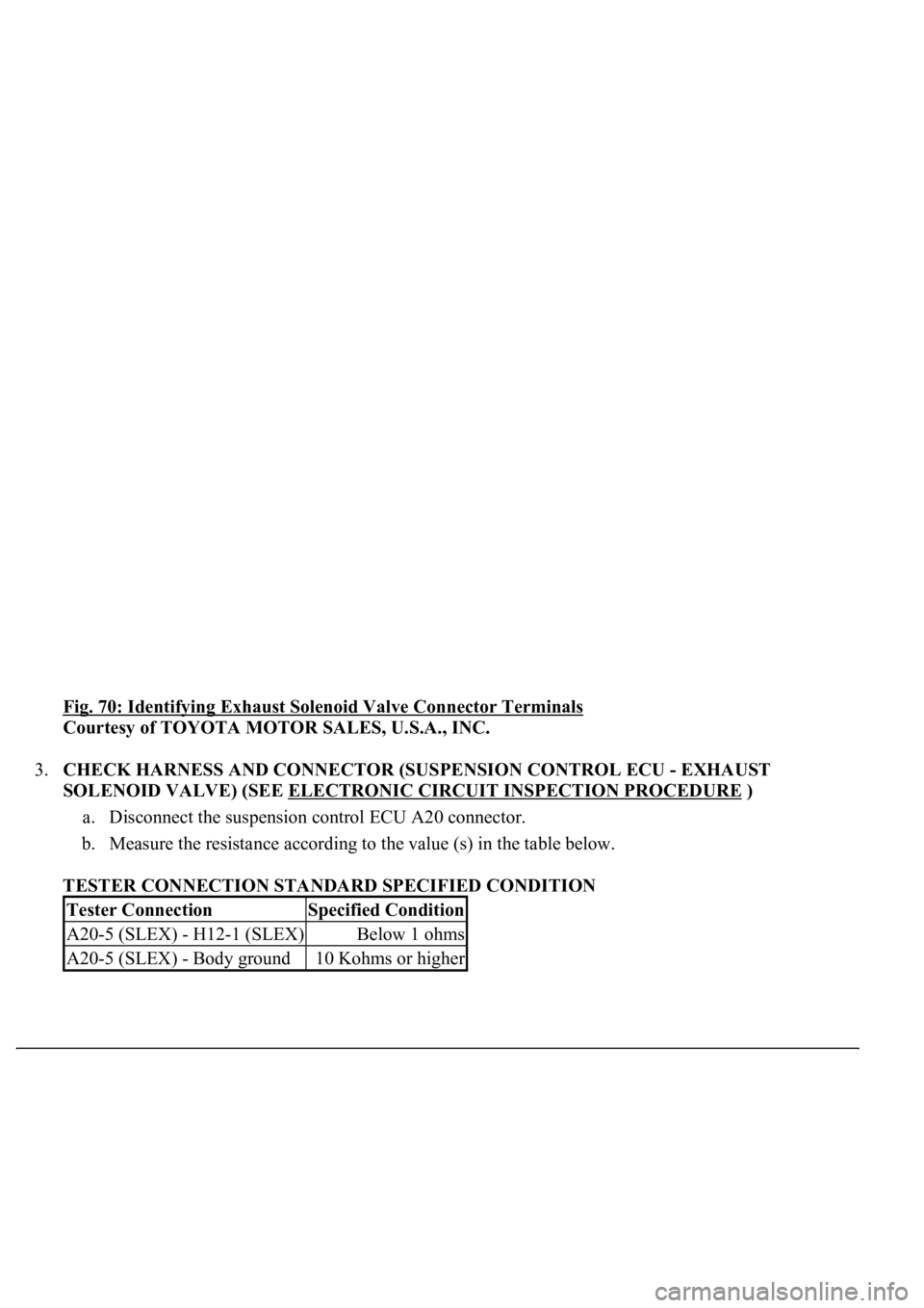
Fig. 70: Identifying Exhaust Solenoid Valve Connector Terminals
Courtesy of TOYOTA MOTOR SALES, U.S.A., INC.
3.CHECK HARNESS AND CONNECTOR (SUSPENSION CONTROL ECU - EXHAUST
SOLENOID VALVE) (SEE ELECTRONIC CIRCUIT INSPECTION PROCEDURE
)
a. Disconnect the suspension control ECU A20 connector.
b. Measure the resistance according to the value (s) in the table below.
TESTER CONNECTION STANDARD SPECIFIED CONDITION
Tester ConnectionSpecified Condition
A20-5 (SLEX) - H12-1 (SLEX)Below 1 ohms
A20-5 (SLEX) - Body ground10 Kohms or higher
Page 553 of 4500
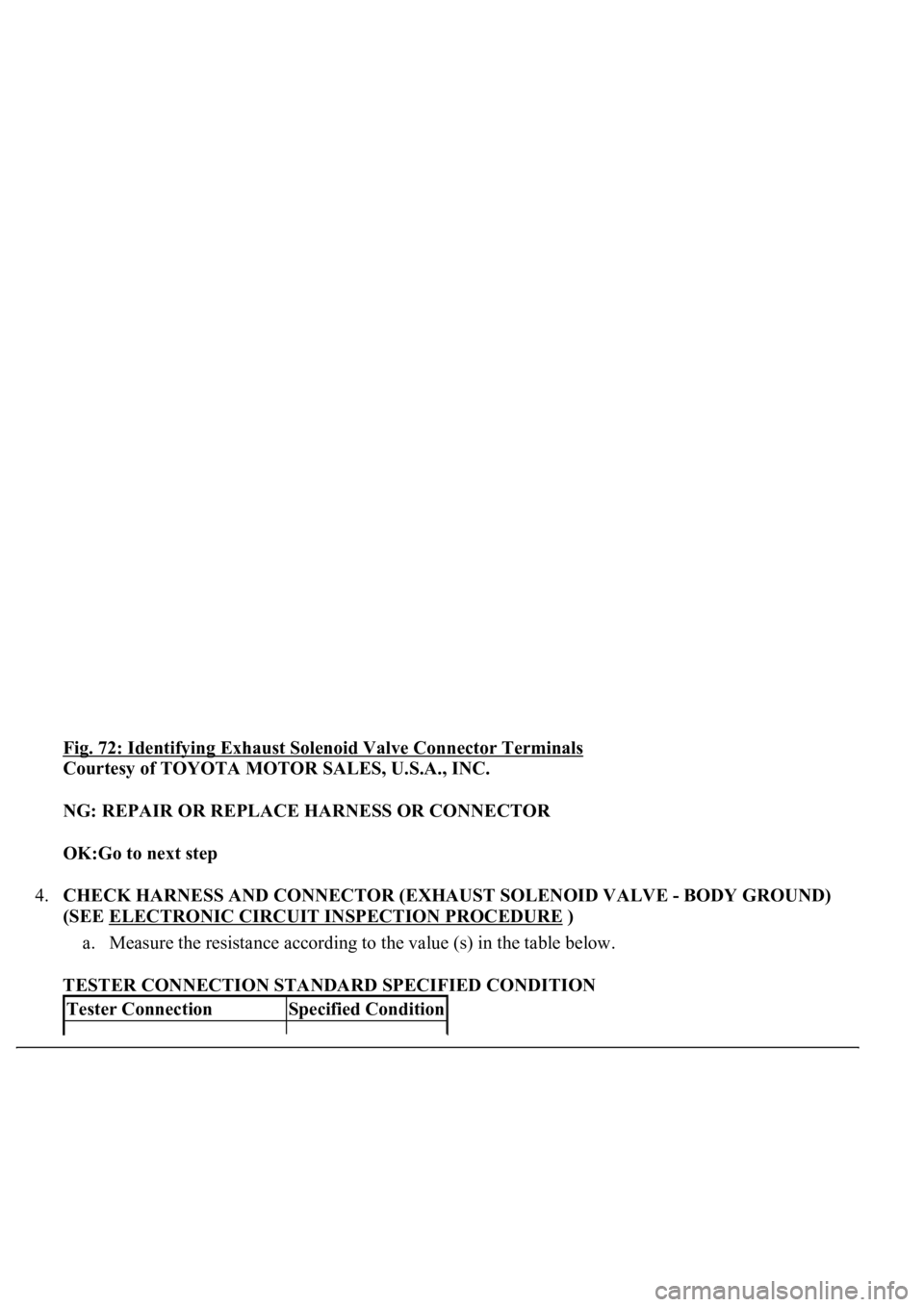
Fig. 72: Identifying Exhaust Solenoid Valve Connector Terminals
Courtesy of TOYOTA MOTOR SALES, U.S.A., INC.
NG: REPAIR OR REPLACE HARNESS OR CONNECTOR
OK:Go to next step
4.CHECK HARNESS AND CONNECTOR (EXHAUST SOLENOID VALVE - BODY GROUND)
(SEE ELECTRONIC CIRCUIT INSPECTION PROCEDURE
)
a. Measure the resistance according to the value (s) in the table below.
TESTER CONNECTION STANDARD SPECIFIED CONDITION
Tester ConnectionSpecified Condition
Page 558 of 4500
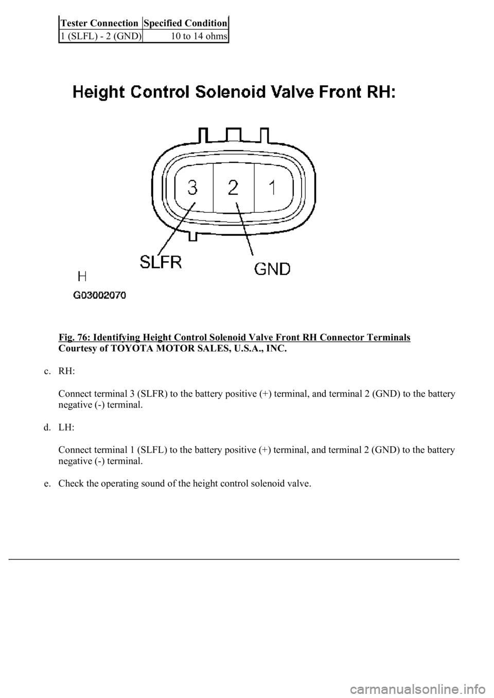
Fig. 76: Identifying Height Control Solenoid Valve Front RH Connector Terminals
Courtesy of TOYOTA MOTOR SALES, U.S.A., INC.
c. RH:
Connect terminal 3 (SLFR) to the battery positive (+) terminal, and terminal 2 (GND) to the battery
negative (-) terminal.
d. LH:
Connect terminal 1 (SLFL) to the battery positive (+) terminal, and terminal 2 (GND) to the battery
negative (-) terminal.
e. Check the operating sound of the height control solenoid valve.
Tester ConnectionSpecified Condition
1 (SLFL) - 2 (GND)10 to 14 ohms


