LEXUS LS430 2003 Factory Manual PDF
LS430 2003
LEXUS
LEXUS
https://www.carmanualsonline.info/img/36/57050/w960_57050-0.png
LEXUS LS430 2003 Factory Manual PDF
Page 3739 of 4500
Fig. 450: Checking Twisted
Courtesy of TOYOTA MOTOR SALES, U.S.A., INC.
12.INSPECT PISTON PIN OIL CLEARANCE
a. Inspect the piston pin oil clearance.
1. Using a caliper gauge, measure the inside diameter of the connecting rod bushing.
Bushing inside diameter:
22.005 to 22.014 mm (0.8663 to 0.8667 in.)
If the bushing inside diameter is not as specified, check the oil clearance.
2. Subtract the piston pin diameter measurement (see step 10) from the bush inside diameter
measurement.
Page 3744 of 4500
Fig. 455: Measuring Circle Runout At Center Journal Using Dial Indicator
Courtesy of TOYOTA MOTOR SALES, U.S.A., INC.
b. Inspect the main journals and crank pins.
1. Using a micrometer, measure the diameter of each main journal and crank pin.
Main journal diameter:
66.988 to 67.000 mm (2.6373 to 2.6378 in.)
Crank pin diameter:
51.982 to 52.000 mm (2.0465 to 2.0472 in.)
If the diameter is not as specified, check the oil clearance (see steps 3 and 7). If necessary, replace
the crankshaft.
2. Check each main journal and crank pin for taper and out-of-round as shown in the illustration.
Maximum taper and out-of-round:
0.02 mm (0.0008 in.)
Page 3750 of 4500
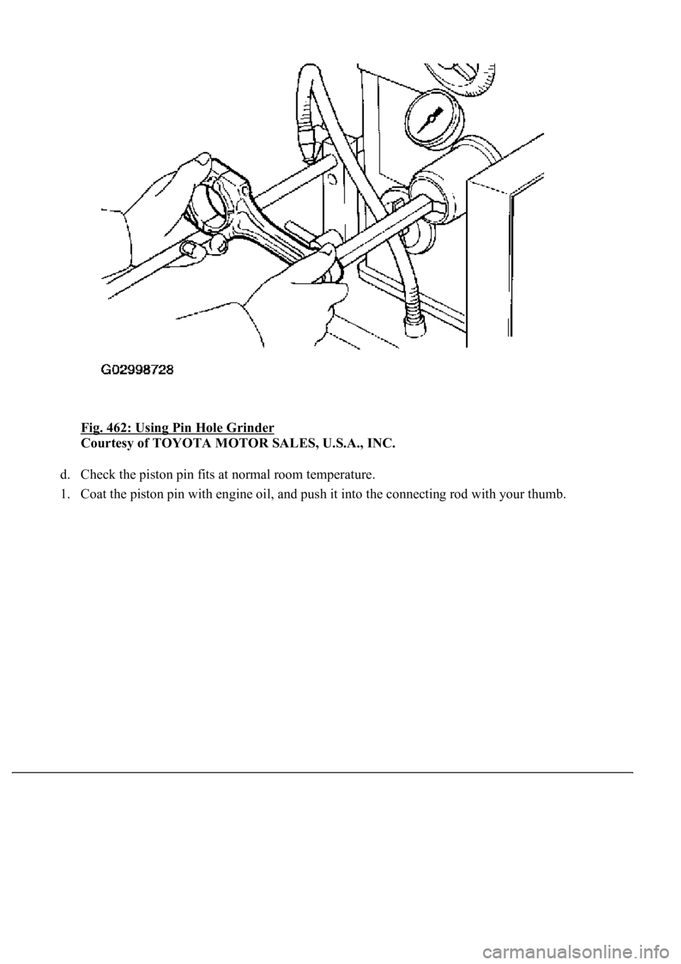
Fig. 462: Using Pin Hole Grinder
Courtesy of TOYOTA MOTOR SALES, U.S.A., INC.
d. Check the piston pin fits at normal room temperature.
1. Coat the piston pin with en
gine oil, and push it into the connecting rod with your thumb.
Page 3774 of 4500
connecting rod cap bolts.
3. Mark the front of the connecting cap bolt with paint.
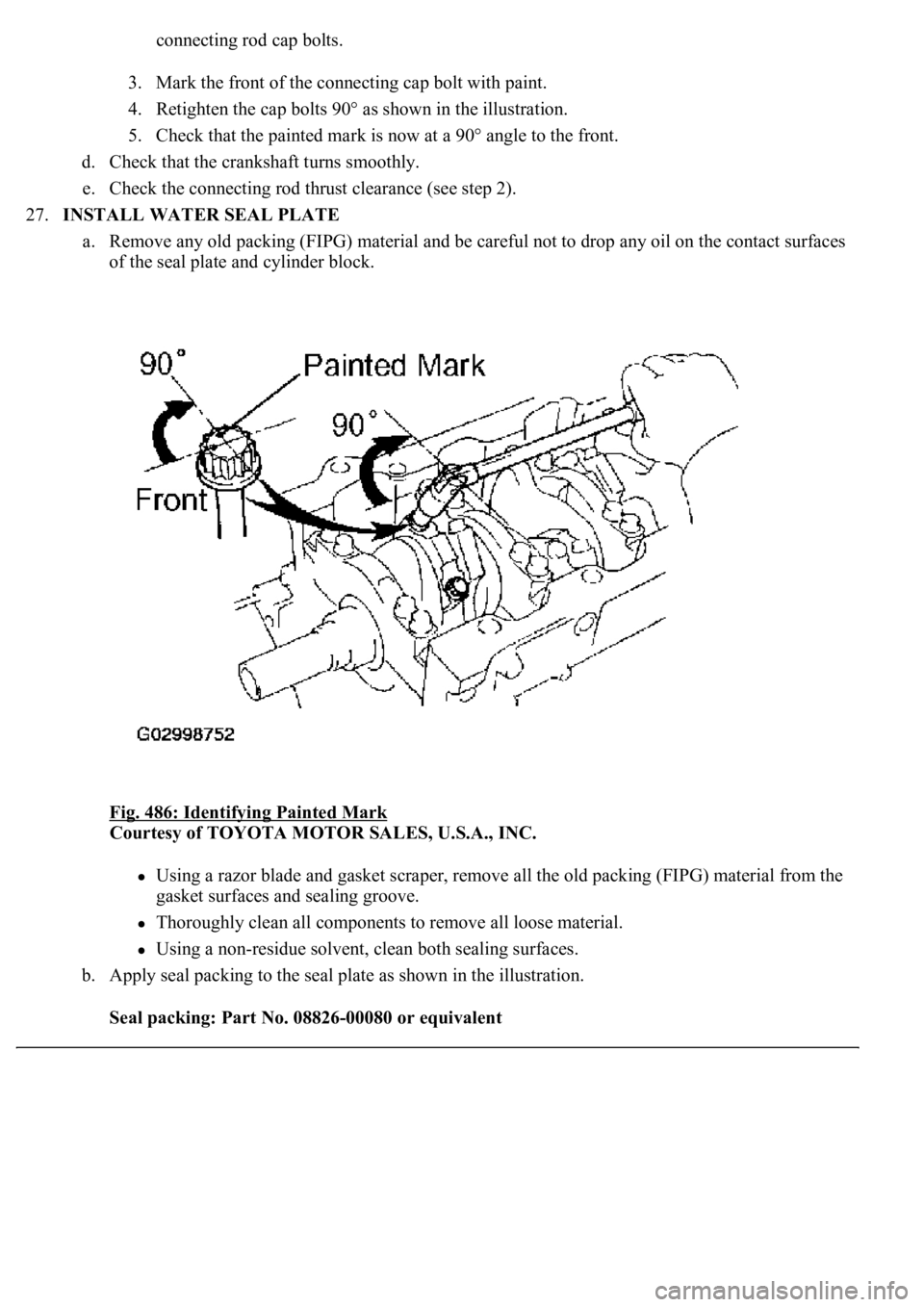
4. Retighten the cap bolts 90° as shown in the illustration.
5. Check that the painted mark is now at a 90° angle to the front.
d. Check that the crankshaft turns smoothly.
e. Check the connecting rod thrust clearance (see step 2).
27.INSTALL WATER SEAL PLATE
a. Remove any old packing (FIPG) material and be careful not to drop any oil on the contact surfaces
of the seal plate and cylinder block.
Fig. 486: Identifying Painted Mark
Courtesy of TOYOTA MOTOR SALES, U.S.A., INC.
Using a razor blade and gasket scraper, remove all the old packing (FIPG) material from the
gasket surfaces and sealing groove.
Thoroughly clean all components to remove all loose material.
Using a non-residue solvent, clean both sealing surfaces.
b. Apply seal packing to the seal plate as shown in the illustration.
Seal packing: Part No. 08826-00080 or equivalent
Page 4110 of 4500
Fig. 11: Covering Disconnected Pipe And Connector With Plastic Bag
Courtesy of TOYOTA MOTOR SALES, U.S.A., INC.
f. Observe these precautions when connecting the fuel tube connector (quick type).
1. Check that there is no damage or foreign matter on the part of the pipe that contacts the
connector.
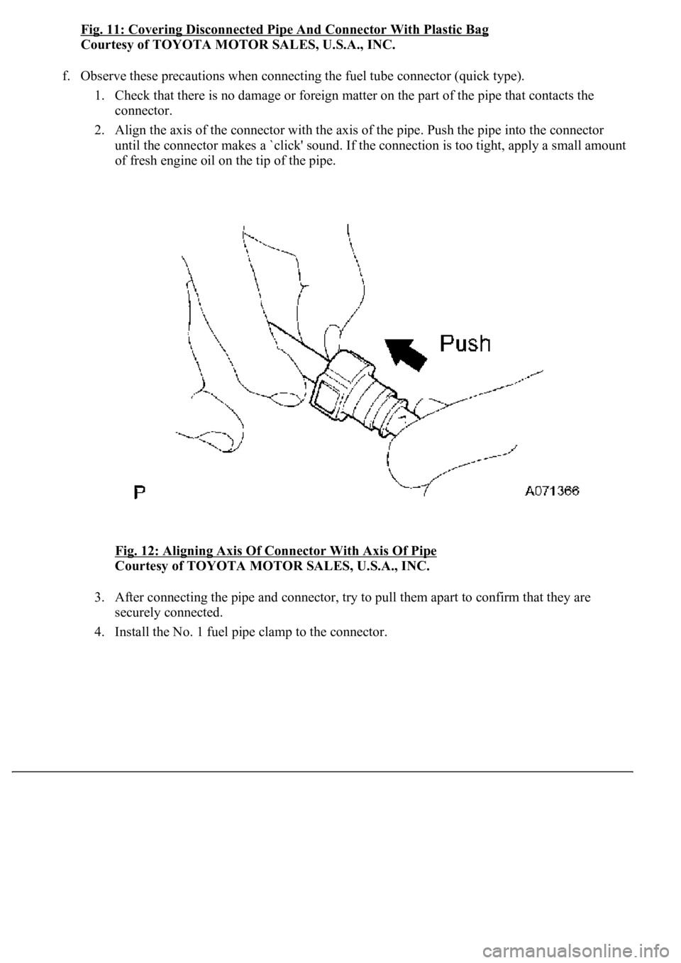
2. Align the axis of the connector with the axis of the pipe. Push the pipe into the connector
until the connector makes a `click' sound. If the connection is too tight, apply a small amount
of fresh engine oil on the tip of the pipe.
Fig. 12: Aligning Axis Of Connector With Axis Of Pipe
Courtesy of TOYOTA MOTOR SALES, U.S.A., INC.
3. After connecting the pipe and connector, try to pull them apart to confirm that they are
securely connected.
4. Install the No. 1 fuel pipe clamp to the connector.
Page 4329 of 4500
Fig. 3: Ignition System Diagram (2 Of 2)
Courtesy of TOYOTA MOTOR SALES, U.S.A., INC.
ON-VEHICLE INSPECTION
1.INSPECT IGNITION COIL ASSY (WITH IGNITER) AND PERFORM SPARK TEST
a. Check for DTCs.
b. Check if sparks occur.
1. Remove the ignition coil (see REPLACEMENT
).
2. Remove the spark plug.
3. Install the spark plug to the ignition coil, and connect the ignition coil connector.
4. Disconnect the 8 injector connectors.
5. Ground the spark plu
g.
Page 4330 of 4500
6. Visually check if spark occurs while the engine is being cranked.
If a spark does not occur, perform the test as follows:
Fig. 4: Spark Test Flow Diagram
Courtesy of TOYOTA MOTOR SALES, U.S.A., INC.
7. Using a 16 mm (0.63 in.) plug wrench, install the spark plugs.
Torque: 18 N.m (180 kgf.cm, 13 ft.lbf)
8. Install the ignition coils (see REPLACEMENT
).