ECO mode LEXUS LS430 2003 Factory Repair Manual
[x] Cancel search | Manufacturer: LEXUS, Model Year: 2003, Model line: LS430, Model: LEXUS LS430 2003Pages: 4500, PDF Size: 87.45 MB
Page 3 of 4500
When there is a malfunction in the contact point of the terminals or installation problems with parts,
removal and installation of the suspected problem parts may return the system to the normal condition
either completely or temporarily.
In order to determine the malfunctioning area, be sure to check the conditions at the time the malfunction
occurred, such as by DTC output and the freeze frame data output, and record it before disconnecting
each connector or removing and installing parts.
Since the ABS with EBD & BA & TRAC & VSC systems may be influenced by a malfunction in the
other systems, be sure to check for DTCs in the other systems.
Be sure to remove and install the skid control ECU, ABS & TRAC actuator and each sensor with the IG
switch OFF unless specified in the inspection procedure.
When removing and installing the skid control ECU, ABS & TRAC actuator and each sensor, be sure to
check that the normal display is output in test mode inspection and in DTC output inspection after
installing all the parts.
After replacing the yaw rate sensor and/or the brake actuator assembly, make sure to perform yaw rate
sensor and deceleration sensor zero point calibration.
(see CALIBRATION
)
CAN communication system is used for the data communication between the skid control ECU (included
in the actuator), the steering angle sensor, and the yaw rate sensor (the deceleration sensor is included). If
there is trouble in the CAN communication line, the DTC in the communication line is output.
If the DTC in the CAN communication line is output, repair the malfunction in the communication line
and troubleshoot the ABS with EBD & BA & TRAC & VSC systems under the condition that data
communication is normal.
Since the CAN communication line has its own length and route, it can not be repaired temporarily with
the bypass wire, etc.
SYSTEM NAME REFERENCE
System NameSee Procedure
Front Power Seat Control SystemINITIALIZATION
Page 22 of 4500
2. Turn the ignition switch to the ON position.
3. Operate the hand-held tester to erase the codes.
HINT:
Refer to the hand-held tester operator's manual for further details.
Check if "VSC" is displayed on the multi-information display.
3.PERFORM ZERO POINT CALIBRATION OF YAW RATE SENSOR AND DECELERATION
SENSOR
a. Check that the steering wheel is in the straight-ahead position and move the shift lever to the P
position.
b. Connect the hand-held tester to the DLC3.
c. Turn the ignition switch to the ON position.
d. Operate the hand-held tester to test mode.
e. Obtain the zero point of the yaw rate sensor and deceleration sensor:
1. Keep the vehicle in the stationar
y condition on a level surface for 2 seconds or more.
Page 30 of 4500
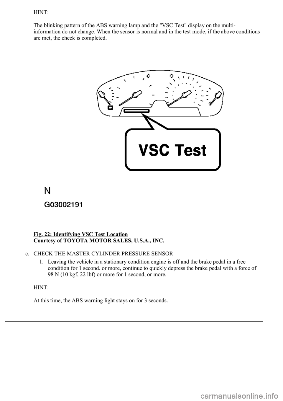
HINT:
The blinking pattern of the ABS warning lamp and the "VSC Test" display on the multi-
information do not change. When the sensor is normal and in the test mode, if the above conditions
are met, the check is completed.
Fig. 22: Identifying VSC Test Location
Courtesy of TOYOTA MOTOR SALES, U.S.A., INC.
c. CHECK THE MASTER CYLINDER PRESSURE SENSOR
1. Leaving the vehicle in a stationary condition engine is off and the brake pedal in a free
condition for 1 second. or more, continue to quickly depress the brake pedal with a force of
98 N (10 kgf, 22 lbf) or more for 1 second, or more.
HINT:
At this time, the ABS warnin
g light stays on for 3 seconds.
Page 32 of 4500
HINT:
The turning direction is not important.
Turning should be completed within 20 seconds. However, it is possible to change the
vehicle speed, stop or move backward.
2. Stop the vehicle and shift the shift lever to the P position, check that the skid control buzzer
sounds for 3 sec.
HINT:
If the skid control buzzer sounds, the sensor check is completed normally.
If the skid control buzzer does not sound, check the skid control buzzer circuit (see SKID
CONTROL BUZZER CIRCUIT ), then perform the sensor check again.
If the skid control buzzer still does not sound, there is a malfunction in the VSC sensor, so
check the DTC.
Drive the vehicle in a 180° circle. At the end of the turn, the direction of the vehicle should
be within 180° +/- 5° of its start position.
Do not spin the wheels.
Even if the VSC sensor check is completed normally, the multi-information displays "VSC
Test" (test mode).
Page 33 of 4500
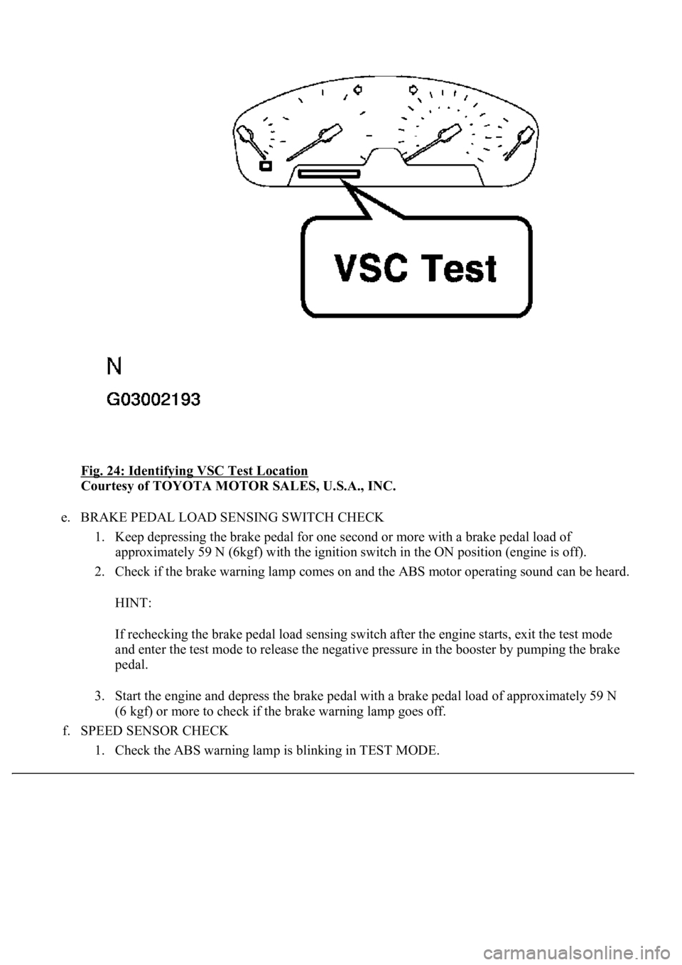
Fig. 24: Identifying VSC Test Location
Courtesy of TOYOTA MOTOR SALES, U.S.A., INC.
e. BRAKE PEDAL LOAD SENSING SWITCH CHECK
1. Keep depressing the brake pedal for one second or more with a brake pedal load of
approximately 59 N (6kgf) with the ignition switch in the ON position (engine is off).
2. Check if the brake warning lamp comes on and the ABS motor operating sound can be heard.
HINT:
If rechecking the brake pedal load sensing switch after the engine starts, exit the test mode
and enter the test mode to release the negative pressure in the booster by pumping the brake
pedal.
3. Start the engine and depress the brake pedal with a brake pedal load of approximately 59 N
(6 kgf) or more to check if the brake warning lamp goes off.
f. SPEED SENSOR CHECK
1. Check the ABS warnin
g lamp is blinking in TEST MODE.
Page 35 of 4500
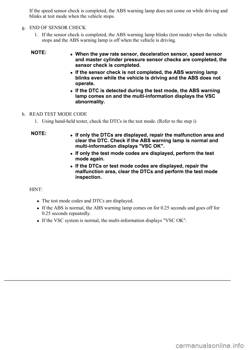
If the speed sensor check is completed, the ABS warning lamp does not come on while driving and
blinks at test mode when the vehicle stops.
g. END OF SENSOR CHECK
1. If the sensor check is completed, the ABS warning lamp blinks (test mode) when the vehicle
stops and the ABS warning lamp is off when the vehicle is driving.
h. READ TEST MODE CODE
1. Using hand-held tester, check the DTCs in the test mode. (Refer to the step i)
HINT:
The test mode codes and DTCs are displayed.
If the ABS is normal, the ABS warning lamp comes on for 0.25 seconds and goes off for
0.25 seconds repeatedly.
If the VSC system is normal, the multi-information displays "VSC OK".
Page 218 of 4500
If the communication is normal when the tool is connected to another vehicle, inspect the DLC3 on
the original vehicle.
If the communication is still impossible when the tool is connected to another vehicle, the problem
is probably in the tool itself, so consult the Service Department listed in the tool's instruction
manual.
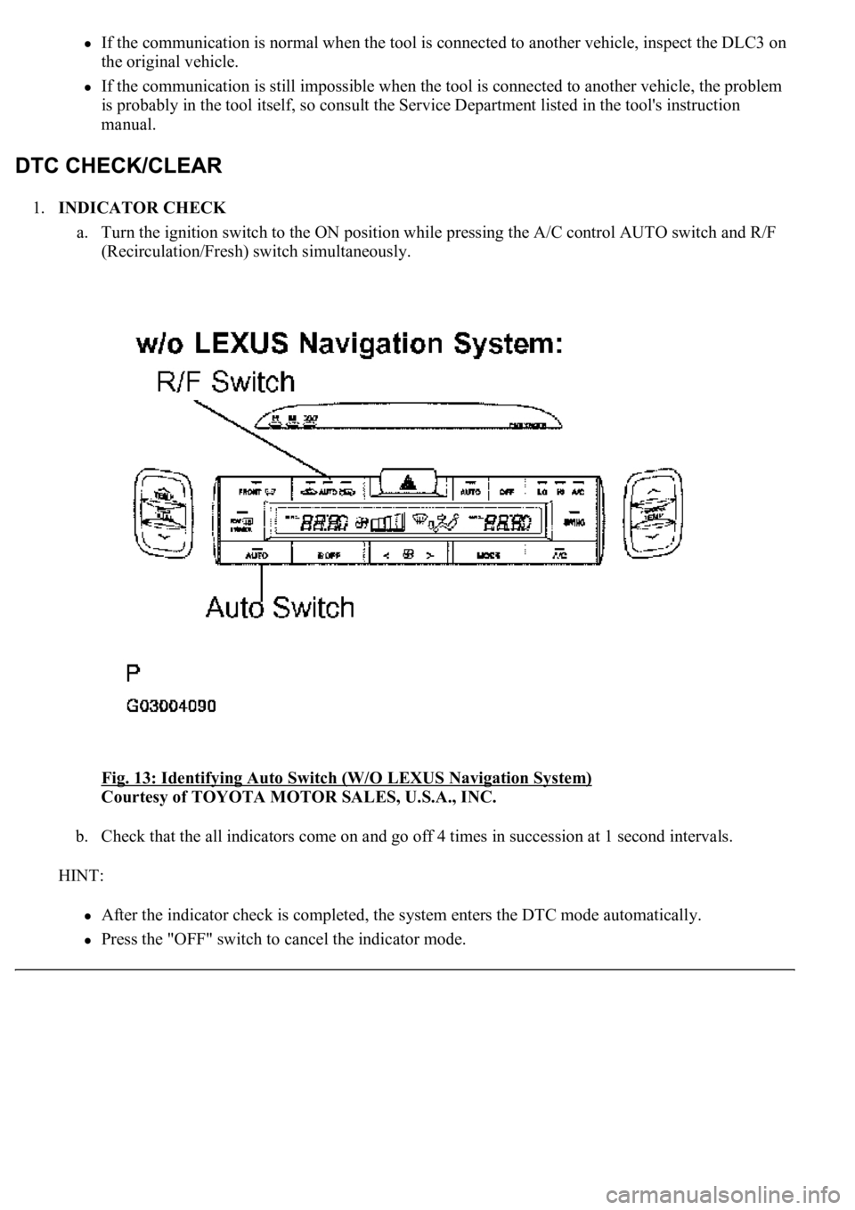
1.INDICATOR CHECK
a. Turn the ignition switch to the ON position while pressing the A/C control AUTO switch and R/F
(Recirculation/Fresh) switch simultaneously.
Fig. 13: Identifying Auto Switch (W/O LEXUS Navigation System)
Courtesy of TOYOTA MOTOR SALES, U.S.A., INC.
b. Check that the all indicators come on and go off 4 times in succession at 1 second intervals.
HINT:
After the indicator check is completed, the system enters the DTC mode automatically.
Press the "OFF" switch to cancel the indicator mode.
Page 228 of 4500

AIR MIX STEP-
DAir mix servomotor target STEP
(Driver side) / min.: 257 STEP
max.: 1571 STEPMAX COOL: Approx. 257 STEP
MAX HOT: Approx. 1,571 STEP-
AIR MIX STEP-
PAir mix servomotor target STEP
(Passenger side) / min.: 257 STEP
max.: 1571 STEPMAX COOL: Approx. 257 STEP
MAX HOT: Approx. 1,571 STEP-
AIR OUT STEP-
DAir outlet servomotor target STEP
(Driver side) / min.: 274 STEP
max.: 2060 STEPFACE: Approx. 274 STEP DEF:
Approx. 2,060 STEP-
AIR OUT STEP-
PAir outlet servomotor target STEP
(Passenger side) / min.: 274 STEP
max.: 2060 STEPFACE: Approx. 274 STEP DEF:
Approx. 2,060 STEP-
HAND FREE
TELHand free telephone / OFF, ON--
BLOWER
LEVELBlower motor speed level / min.:
0 level max.: 31 levelIncreases in the range between 0 and
31 as the speed increase-
AMBI TEMP
Adjusted ambient temperature /
min.: -30.8°C (-23.44°F) max.:
50.8°C (123.44°F)
--
LOW VOLT
COUNT+B abnormal low voltage / min.: 0
times max.: 255 times--
EMISS GAS
SENSEmission gas / min.: 0 V max.:
255 VIncreases as the gas amount increases-
SET TEMP
SHIFTShift set temperature / +2C, +1C,
NORMAL, -1C, -2CCustomized value will be displayed-
AIR INLET
MODEAir inlet mode / AUTO,
MANUALCustomized value will be displayed-
COMPRESSOR
MODECompressor mode / AUTO,
MANUALCustomized value will be displayed-
COMPRS/DEF
OPERCompressor/ DEF operation
mode /LINK, NORMALCustomized value will be displayed-
MOTOR
INITIALIZEMotor initialize after IG SW being
turned OFFCustomized value will be displayed-
EVAP CTRLEvaporator control /AUTO,
MANUALCustomized value will be displayed-
GAS SENS
SHIFT
Emission Gas Sensor Shift / MU
MORE, MORE, LI MORE,
NORMAL, LI LESS, LESS, MU
LESS
Customized value will be displayed-
AUTO MODESwing resister auto mode /
AUTO, MANUALCustomized value will be displayed-
BUTTON PRS
BUZButton press buzzer / ON, OFFCustomized value will be displayed-
FILTER SENSFilter sensor / LESS, NORMAL,
MORECustomized value will be displayed-
Page 231 of 4500

IG - GND (A11-9
- A11-1)LG-R -
W-BPower source (IG)Ignition switch OFF.0 V
TSDr - GND
(A11-19 - A11-1)L - W-BSolar sensor signal (Driver
side)Ignition switch ON. Solar sensor
subjected to electric light.0.8 to 4.3 V
TSDr - GND
(A11-19 - A11-1)L - W-BSolar sensor signal (Driver
side)Ignition switch ON. Solar sensor
covered by a cloth.Below 0.8 V
TSPa - GND
(A11-20 - A11-1)G-R - W-
BSolar sensor signal
(Passenger side)Ignition switch ON. Solar sensor
subjected to electric light.0.8 to 4.3 V
TSPa - GND
(A11-20 - A11-1)G-R - W-
BSolar sensor signal
(Passenger side)Ignition switch ON. Solar sensor
covered by a cloth.Below 0.8 V
+B - GND (A11-
21 - A11-1)B-Y - W-
BPower source (Back-up)Always10 to 14 V
DGS - SG-1
(A11-29 - A13-8)B - YExhaust gas sensor signal
After 30 seconds from Ignition
switch ON and the sensor is
exposed to the exhaust gas.
1.0 to 4.5 V
DS1 - GND
(A12-1 - A11-1)V - W-BSwing grill STEP motor
signal
Ignition switch ON. Blower
motor: Operating Mode selector:
BI-LEVEL Intelligent swing
register: ON
Pulse
generation
Symbols
(Terminal No.)Wiring
colorTerminal DescriptionConditionSpecification
DS2 - GND
(A12-2 - A11-1)G - W-BSwing grill STEP motor
signal
Ignition switch ON. Blower
motor: Operating Mode selector:
BI-LEVEL Intelligent swing
register: ON
Pulse
generation
PS1 - GND (A12-
3 - A11-1)R-B - W-
BSwing grill STEP motor
signal
Ignition switch ON. Blower
motor: Operating Mode selector:
BI-LEVEL Intelligent swing
register: ON
Pulse
generation
PS2 - GND (A12-
4 - A11-1)B - W-BSwing grill STEP motor
signal
Ignition switch ON. Blower
motor: Operating Mode selector:
BI-LEVEL Intelligent swing
register: ON
Pulse
generation
PS3 - GND (A12-
5 - A11-1)P - W-BSwing grill STEP motor
signal
Ignition switch ON. Blower
motor: Operating Mode selector:
BI-LEVEL Intelligent swing
register: ON
Pulse
generation
PS4 - GND (A12-
6 - A11-1)Y-R - W-
BSwing grill STEP motor
signal
Ignition switch ON. Blower
motor: Operating Mode selector:
BI-LEVEL Intelligent swing
register: ON
Pulse
generation
DUAL - DrGND
(A12-7 - A12-11)O - LG-RDual temperature control
signalIgnition switch ON. Dual switch
ON.Below 1.0 V
DUAL - DrGND
(A12-7 - A12-11)O - LG-RDual temperature control
signalIgnition switch ON. Dual switch
OFF.10 to 14 V
Page 233 of 4500

12)side)switch ON.
DrDN - DrGND
(A12-21 - A12-
11)P-L - LG-
RTemperature control
switch signal (Driver side)Push driver temperature switch
OFF.10 to 14 V
DrDN - DrGND
(A12-21 - A12-
11)P-L - LG-
RTemperature control
switch signal (Driver side)Push driver temperature switch
ON.Below 1.0 V
DrUP - DrGND
(A12-22 - A12-
11)V-W -
LG-RTemperature control
switch signal (Driver side)Push driver temperature switch
OFF.10 to 14 V
DrUP - DrGND
(A12-22 - A12-
11)V-W -
LG-RTemperature control
switch signal (Driver side)Push driver temperature switch
ON.Below 1.0 V
PS+B - GND
(A12-24 - A11-1)R-G - W-
BSwing grill STEP motor
operation voltageAlways10 to 14 V
TFACEPa - SG-4
(A13-14 - A13-
11)B-Y - Y-
GDuct sensor signal
(Passenger side)Ignition switch ON. Passenger
side duct sensor temperature 25 °
C (77 °F).
1.8 to 2.2 V
TFACEPa - SG-4
(A13-14 - A13-
11)B-Y - Y-
GDuct sensor signal
(Passenger side)Ignition switch ON. Passenger
side duct sensor temperature 50 °
C (122 °F).
0.8 to 1.2 V
TFACEDr - SG-3
(A13-15 - A13-
10)GR-R -
R-WDuct sensor signal (Driver
side)Ignition switch ON. Passenger
side duct sensor temperature 25 °
C (77 °F).
1.8 to 2.2 V
TFACEDr - SG-3
(A13-15 - A13-
10)GR-R -
R-WDuct sensor signal (Driver
side)Ignition switch ON. Passenger
side duct sensor temperature 50 °
C (122 °F).
0.8 to 1.2 V
TR - SG-2 (A13-
16 - A13-9)W-L - Y-
BRoom temperature sensor
signalIgnition switch ON. Room
temperature 25 °C (77°F).1.8 to 2.2 V
TR - SG-2 (A13-
16 - A13-9)W-L - Y-
BRoom temperature sensor
signalIgnition switch ON. Room
temperature 40 °C (104°F).0.8 to 1.2 V
NOX - Body
ground (A13-17 -
Body ground)L-B -
Body
ground
Exhaust gas sensor signal
After 120 seconds from Ignition
switch ON and the sensor is
exposed to the exhaust gas.
1.0 to 4.5 V
AMDr1 - GND
(A37-1 - A11-1)BR - W-B
Air mix servomotor
operation signal (Driver
side)During actuator check mode.
Change display code 0 to display
code 9.Pulse
generation
AMDr2 - GND
(A37-2 - A11-1)BR-B -
W-BAir mix servomotor
operation signal (Driver
side)During actuator check mode.
Change display code 0 to display
code 9.Pulse
generation
AMDr3 - GND
(A37-3 - A11-1)BR-W -
W-BAir mix servomotor
operation signal (Driver
side)During actuator check mode.
Change display code 0 to display
code 9.Pulse
generation
AMDr4 - GND
(A37-4 - A11-1)BR-Y -
W-BAir mix servomotor
operation signal (Driver During actuator check mode.
Change display code 0 to display Pulse
generation