check oil LEXUS LS430 2003 Factory Owner's Manual
[x] Cancel search | Manufacturer: LEXUS, Model Year: 2003, Model line: LS430, Model: LEXUS LS430 2003Pages: 4500, PDF Size: 87.45 MB
Page 2945 of 4500
Standard: 0.6 to 1.0 V
If the result is not as specified, replace the accelerator pedal position sensor.
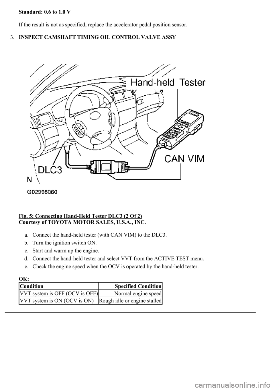
3.INSPECT CAMSHAFT TIMING OIL CONTROL VALVE ASSY
Fig. 5: Connecting Hand
-Held Tester DLC3 (2 Of 2)
Courtesy of TOYOTA MOTOR SALES, U.S.A., INC.
a. Connect the hand-held tester (with CAN VIM) to the DLC3.
b. Turn the ignition switch ON.
c. Start and warm up the engine.
d. Connect the hand-held tester and select VVT from the ACTIVE TEST menu.
e. Check the engine speed when the OCV is operated by the hand-held tester.
OK:
ConditionSpecified Condition
VVT system is OFF (OCV is OFF)Normal engine speed
VVT system is ON (OCV is ON)Rough idle or engine stalled
Page 2947 of 4500
Courtesy of TOYOTA MOTOR SALES, U.S.A., INC.
a. Check the output voltage.
1. Apply battery voltage across terminals 1 (+B) and 2 (E2G).
2. Using a voltmeter, connect the positive (+) tester probe to terminal VG, and negative (-)
tester probe to terminal E2G.
3. Blow air into the MAF meter, and check that the voltage fluctuates.
b. Measure the resistance between terminals 4 (THA) and 5 (E2).
STANDARD:
If the result is not as specified, replace the MAF meter.
2.INSPECT CAMSHAFT TIMING OIL CONTROL VALVE ASSY
ConditionSpecified Condition
-20°C (-4°F)13.6 to 18.4 kohms
20°C (68°F)2.21 to 2.69 kohms
60°C (140°F)0.493 to 0.667 kohms
Page 3167 of 4500
3.SYSTEM FUNCTION
When the steering lock ECU detects that the unlock warning switch is ON, the ECU provides current to
the transponder key coil and produces a faint electric wave. A transponder chip in the key and receives
the faint electric wave. Upon receiving the faint electric wave, the transponder chip outputs a key ID code
signal. The transponder key coil receives this signal, the transponder key amplifier amplifies it, and then
the signal is transmitted to the ECU.
The ECU matches the key's ID code with the vehicle's ID code, which was previously registered in the
ECU and then communicates the results to the ECM using SFI communication.
After the identification results show that the key's ID code matches the vehicle's ID code and the ECU has
confirmed their match: 1) the immobilizer system does not immobilize the engine and the engine starting
controls (fuel injection control and ignition control) enter standby mode; and 2) the ECU transmits a
security indicator signal that communicates "indicator off" to the theft warning ECU (theft deterrent
ECU). Then, the theft warning ECU turns off the security indicator lamp.
HINT:
Use this procedure to troubleshoot the engine immobilizer system.
The hand-held tester should be used in steps 4, 5 and 7.
1.VEHICLE BROUGHT TO WORKSHOP
2.CUSTOMER PROBLEM ANALYSIS CHECK AND SYMPTOM CHECK (See CUSTOMER
PROBLEM ANALYSIS CHECK )
3.CRANK ENGINE FOR MORE THAN 10 SECONDS
4.CHECK FOR DTCS
a. Check for DTCs and note any codes that are output.
b. Delete the DTC.
c. Recheck for DTCs. Based on the DTC output in (a), try to force output of the same SFI system
DTC or engine immobilizer system DTC by simulating the operation indicated by the DTC.
1. If the DTC does not reoccur, proceed to A.
2. If the SFI system DTC reoccurs, proceed to B.
3. If the engine immobilizer system DTC reoccurs, proceed to C.
B: Go to SFI SYSTEM (See HOW TO PROCEED WITH TROUBLESHOOTING
)
C: Go to step 8
illuminates or starts blinking.
Page 3227 of 4500
receives the faint electric wave. Upon receiving the faint electric wave, the transponder chip outputs a key
ID code signal. The transponder key coil receives this signal, the transponder key amplifier amplifies it,
and then the signal is transmitted to the ECU.
The ECU matches the key's ID code with the vehicle's ID code, which was previously registered in the
ECU, and then communicates the results to the ECM using SFI communication.
After the identification results show that the key's ID code matches the vehicle's ID code and the ECU has
confirmed their match: 1) the immobilizer system does not immobilize the engine and the engine starting
controls (fuel injection control and ignition control) enter standby mode; and 2) the ECU transmits a
security indicator signal that communicates "indicator off" to the theft warning ECU (theft deterrent
ECU). Then, the theft warning ECU turns off the security indicator lamp.
HINT:
<00380056004800030057004b004c00560003005300550052004600480047005800550048000300570052000300570055005200580045004f00480056004b00520052005700030057004b0048000300480051004a004c005100480003004c00500050005200
45004c004f004c005d0048005500030056005c005600570048[m. The hand-held tester should be used in steps
4, 5 and 7.
1.VEHICLE BROUGHT TO WORKSHOP
2.CUSTOMER PROBLEM ANALYSIS CHECK AND SYMPTOM CHECK (See CUSTOMER
PROBLEM ANALYSIS CHECK )
3.CRANK ENGINE FOR MORE THAN 10 SECONDS
4.CHECK FOR DTCS
a. Check for DTCs and note any codes that are output.
b. Delete the DTC.
c. Recheck for DTCs. Based on the DTC output in (a), try to force output of the same SFI system
DTC or engine immobilizer system DTC by simulating the operation indicated by the DTC.
1. If the DTC does not reoccur, proceed to A.
2. If the SFI system DTC reoccurs, proceed to B.
3. If the engine immobilizer system DTC reoccurs, proceed to C.
B: Go to SFI SYSTEM (See DIAGNOSTIC TROUBLE CODE CHART
)
C: Go to step 8
A: Go to next step
5.READ DATA LIST USING HAND-HELD TESTER
a. Connect the hand-held tester to the Controller Area Network Vehicle Interface Module (CAN
VIM). Then connect the CAN VIM to the DLC3.
b. Turn the ignition switch ON and push the hand-held tester main switch ON.
c. Read the DATA LIST.
Page 3279 of 4500
INSPECTION
1.INSPECT ENGINE COOLANT (See REPLACEMENT
)
2.INSPECT ENGINE OIL (See ON
-VEHICLE INSPECTION )
3.INSPECT BATTERY (See REPLACEMENT
)
4.INSPECT AIR CLEANER FILTER ELEMENT SUB-ASSY
5.INSPECT SPARK PLUG (See REPLACEMENT
)
6.INSPECT FAN AND GENERATOR V BELT
HINT:
Use of the automatic tensioner has made tension and flexibility measurements unnecessary.
a. Check that the indicator mark on the automatic tensioner is within range A as shown in the
illustration.
b. When the mark is out of the standard range, replace the V belt with a new one.
Page 3283 of 4500
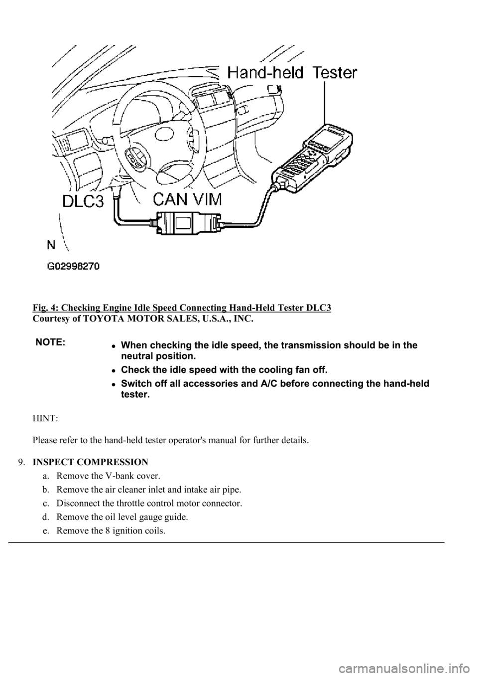
Fig. 4: Checking Engine Idle Speed Connecting Hand-Held Tester DLC3
Courtesy of TOYOTA MOTOR SALES, U.S.A., INC.
HINT:
Please refer to the hand-held tester operator's manual for further details.
9.INSPECT COMPRESSION
a. Remove the V-bank cover.
b. Remove the air cleaner inlet and intake air pipe.
c. Disconnect the throttle control motor connector.
d. Remove the oil level gauge guide.
e. Remove the 8 i
gnition coils.
Page 3284 of 4500
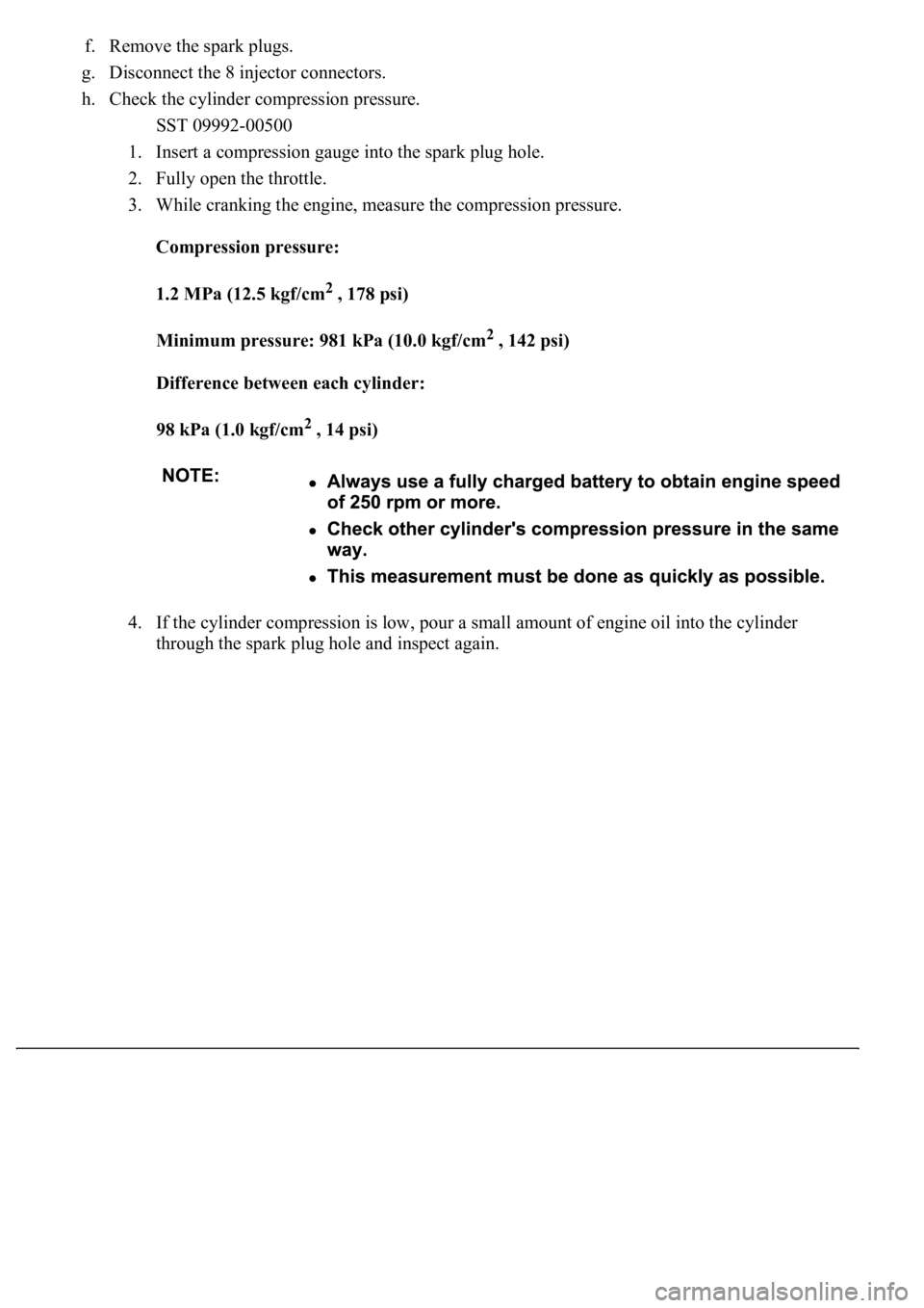
f. Remove the spark plugs.
g. Disconnect the 8 injector connectors.
h. Check the cylinder compression pressure.
SST 09992-00500
1. Insert a compression gauge into the spark plug hole.
2. Fully open the throttle.
3. While cranking the engine, measure the compression pressure.
Compression pressure:
1.2 MPa (12.5 kgf/cm
2 , 178 psi)
Minimum pressure: 981 kPa (10.0 kgf/cm
2 , 142 psi)
Difference between each cylinder:
98 kPa (1.0 kgf/cm
2 , 14 psi)
4. If the cylinder compression is low, pour a small amount of engine oil into the cylinder
throu
gh the spark plug hole and inspect again.
Page 3285 of 4500
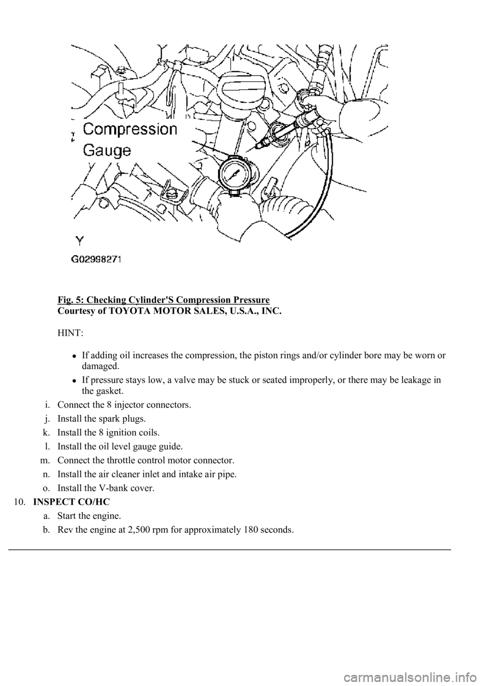
Fig. 5: Checking Cylinder'S Compression Pressure
Courtesy of TOYOTA MOTOR SALES, U.S.A., INC.
HINT:
If adding oil increases the compression, the piston rings and/or cylinder bore may be worn or
damaged.
If pressure stays low, a valve may be stuck or seated improperly, or there may be leakage in
the gasket.
i. Connect the 8 injector connectors.
j. Install the spark plugs.
k. Install the 8 ignition coils.
l. Install the oil level gauge guide.
m. Connect the throttle control motor connector.
n. Install the air cleaner inlet and intake air pipe.
o. Install the V-bank cover.
10.INSPECT CO/HC
a. Start the engine.
b. Rev the engine at 2,500 rpm for approximately 180 seconds.
Page 3314 of 4500
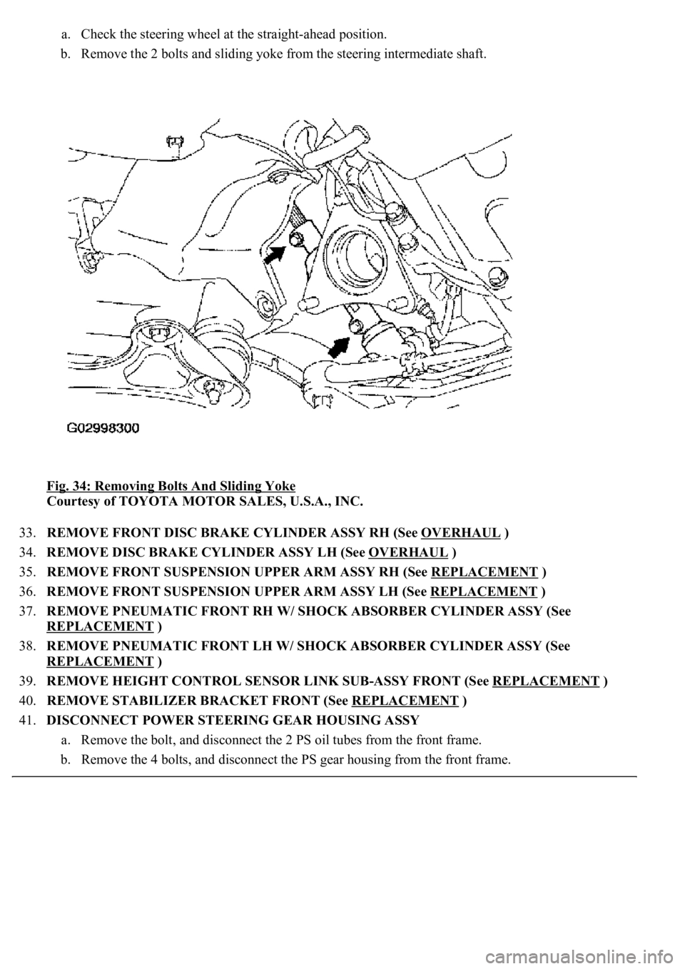
a. Check the steering wheel at the straight-ahead position.
b. Remove the 2 bolts and sliding yoke from the steering intermediate shaft.
Fig. 34: Removing Bolts And Sliding Yoke
Courtesy of TOYOTA MOTOR SALES, U.S.A., INC.
33.REMOVE FRONT DISC BRAKE CYLINDER ASSY RH (See OVERHAUL
)
34.REMOVE DISC BRAKE CYLINDER ASSY LH (See OVERHAUL
)
35.REMOVE FRONT SUSPENSION UPPER ARM ASSY RH (See REPLACEMENT
)
36.REMOVE FRONT SUSPENSION UPPER ARM ASSY LH (See REPLACEMENT
)
37.REMOVE PNEUMATIC FRONT RH W/ SHOCK ABSORBER CYLINDER ASSY (See
REPLACEMENT
)
38.REMOVE PNEUMATIC FRONT LH W/ SHOCK ABSORBER CYLINDER ASSY (See
REPLACEMENT
)
39.REMOVE HEIGHT CONTROL SENSOR LINK SUB-ASSY FRONT (See REPLACEMENT
)
40.REMOVE STABILIZER BRACKET FRONT (See REPLACEMENT
)
41.DISCONNECT POWER STEERING GEAR HOUSING ASSY
a. Remove the bolt, and disconnect the 2 PS oil tubes from the front frame.
b. Remove the 4 bolts, and disconnect the PS gear housing from the front frame.
Page 3361 of 4500
140.INSTALL ENGINE UNDER COVER NO.2
141.INSTALL ENGINE UNDER COVER NO.1
142.INSTALL FRONT WHEEL
143.INSTALL AIR CLEANER ASSY
144.INSTALL INTAKE AIR CONNECTOR PIPE
145.INSTALL AIR CLEANER INLET NO.1
146.INSTALL V-BANK COVER
147.INSTALL HOOD SUB-ASSY (See ADJUSTMENT
and OVERHAUL )
148.CONNECT BATTERY NEGATIVE TERMINAL
149.ADD AUTOMATIC TRANSMISSION FLUID
150.ADD ENGINE COOLANT (See REPLACEMENT
)
151.ADD ENGINE OIL (See ON
-VEHICLE INSPECTION )
152.ADD POWER STEERING FLUID
153.BLEED POWER STEERING FLUID
154.INSPECT AUTOMATIC TRANSMISSION FLUID (See ADJUSTMENT
)
155.INSPECT ENGINE OIL LEAKS
156.CHECK FOR ENGINE COOLANT LEAKS
157.INSPECT FOR FUEL LEAKS
158.CHECK FOR EXHAUST GAS LEAKS
159.INSPECT AND ADJUST FRONT WHEEL ALIGNMENT
160.INSPECT IGNITION TIMING
161.INSPECT ENGINE IDLE SPEED
162.INSPECT CO/HC
163.ADJUST ENGINE (See INSPECTION
)
164.CHECK ABS SPEED SENSOR SIGNAL (See TEST MODE PROCEDURE
)
OVERHAUL
1.REMOVE SPARK PLUG
2.REMOVE OIL FILLER CAP SUB-ASSY
3.REMOVE CYLINDER HEAD COVER SUB-ASSY LH
a. Remove the 9 bolts, 9 seal washers, cylinder head cover and gasket.
4.REMOVE CYLINDER HEAD COVER SUB-ASSY
a. Remove the 9 bolts, 9 seal washers, c
ylinder head cover and gasket.