Lock actuator LEXUS LS430 2003 Factory Repair Manual
[x] Cancel search | Manufacturer: LEXUS, Model Year: 2003, Model line: LS430, Model: LEXUS LS430 2003Pages: 4500, PDF Size: 87.45 MB
Page 7 of 4500

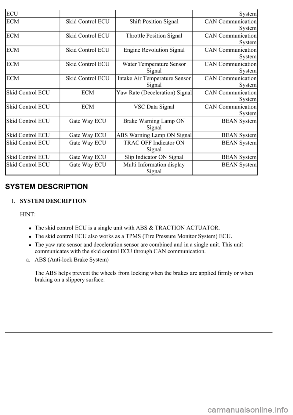
1.SYSTEM DESCRIPTION
HINT:
The skid control ECU is a single unit with ABS & TRACTION ACTUATOR.
The skid control ECU also works as a TPMS (Tire Pressure Monitor System) ECU.
The yaw rate sensor and deceleration sensor are combined and in a single unit. This unit
communicates with the skid control ECU through CAN communication.
a. ABS (Anti-lock Brake System)
The ABS helps prevent the wheels from locking when the brakes are applied firmly or when
braking on a slippery surface.
ECUSystem
ECMSkid Control ECUShift Position SignalCAN Communication
System
ECMSkid Control ECUThrottle Position SignalCAN Communication
System
ECMSkid Control ECUEngine Revolution SignalCAN Communication
System
ECMSkid Control ECUWater Temperature Sensor
SignalCAN Communication
System
ECMSkid Control ECUIntake Air Temperature Sensor
SignalCAN Communication
System
Skid Control ECUECMYaw Rate (Deceleration) SignalCAN Communication
System
Skid Control ECUECMVSC Data SignalCAN Communication
System
Skid Control ECUGate Way ECUBrake Warning Lamp ON
SignalBEAN System
Skid Control ECUGate Way ECUABS Warning Lamp ON SignalBEAN System
Skid Control ECUGate Way ECUTRAC OFF Indicator ON
SignalBEAN System
Skid Control ECUGate Way ECUSlip Indicator ON SignalBEAN System
Skid Control ECUGate Way ECUMulti Information display
SignalBEAN System
Page 8 of 4500

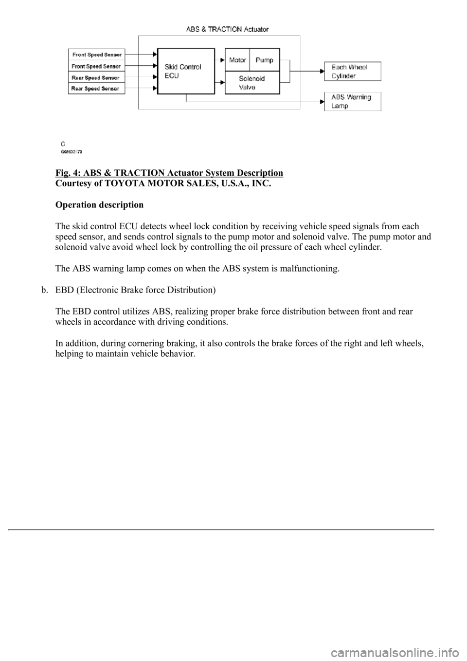
Fig. 4: ABS & TRACTION Actuator System Description
Courtesy of TOYOTA MOTOR SALES, U.S.A., INC.
Operation description
The skid control ECU detects wheel lock condition by receiving vehicle speed signals from each
<005600530048004800470003005600480051005600520055000f00030044005100470003005600480051004700560003004600520051005700550052004f00030056004c004a00510044004f005600030057005200030057004b0048000300530058005000
53000300500052005700520055000300440051004700030056[olenoid valve. The pump motor and
solenoid valve avoid wheel lock by controlling the oil pressure of each wheel cylinder.
The ABS warning lamp comes on when the ABS system is malfunctioning.
b. EBD (Electronic Brake force Distribution)
The EBD control utilizes ABS, realizing proper brake force distribution between front and rear
wheels in accordance with driving conditions.
In addition, during cornering braking, it also controls the brake forces of the right and left wheels,
helping to maintain vehicle behavior.
Page 89 of 4500

VEHICLE CONDITION / TEST DETAILS DESCRIPTION
OK: Go to next step
<0037004b00480003005200530048005500440057004c0052005100030056005200580051004700030052004900030057004b0048000300240025003600030050005200570052005500030056004b00520058004f00470003004500480003004b0048004400
5500470011[
NG: Go to step 2
OK: REPLACE ABS & TRACTION ACTUATOR ASSY (SEE REPLACEMENT
)
2.INSPECT FUSE (ABS2 FUSE)
a. Remove the ABS 2 fuse from fusible link block.
b. Measure the resistance according to the value (s) in the table below.
Standard:
ABS 2 FUSE DESCRIPTION
ItemVehicle Condition / Test DetailsVehicle Condition / Test Details
ABS MOT RELAYTurns ABS motor relay / ON or OFFON: Motor relay ON
ABS 2 FuseBelow 1 ohms (Continuity)
Page 482 of 4500

FBL+ (A21-6) -
FBL- (A21-16)G-W - G-
OSuspension control
actuator (FL)IG switch ONBelow 1
ohms
SLRL (A21-7) -
GND (A20-4)P-L - W-BHeight control solenoid
valve (RL)IG switch ONBelow 1 V
SLRL (A21-7) -
GND (A20-4)P-L - W-BHeight control solenoid
valve (RL)Engine idling, height control switch
from "NORM" to "HIGH" or
reverse
8 V or more
SLRR (A21-8) -
GND (A20-4)P - W-BHeight control solenoid
valve (RR)IG switch ONBelow 1 V
SLRR (A21-8) -
GND (A20-4)P - W-BHeight control solenoid
valve (RR)Engine idling, height control switch
from "NORM" to "HIGH" or
reverse
8 V or more
RM+ (A21-17) -
GND (A20-4)BR-Y - W-
BMotor lock (+)
Engine idling, height control switch
from "NORM" to "HIGH" during
compressor operation
Below 1 V
RM- (A21-18) -
GND (A20-4)BR-B - W-
BMotor lock (-)AlwaysBelow 1
ohms
SHR2 (A21-19) -
GND (A20-4)W - W-BHeight control sensor
(HID rear)IG switch ON0.5 to 4.5 V
SHFR (A21-20) -
GND (A20-4)B-W - W-
BHeight control sensor
(FR)IG switch ON0.5 to 4.5 V
SHFR (A21-20) -
GND (A20-4)B-W - W-
BHeight control sensor
(FR)Engine idling, height control switch
"NORM"Approx. 2.5
V
SHF2 (A21-21) -
GND (A20-4)V-G - W-BHeight control sensor
(HID front)IG switch ON0.5 to 4.5 V
SHFL (A21-22) -
GND (A20-4)L - W-BHeight control sensor
(FL)IG switch ON0.5 to 4.5 V
SHFL (A21-22) -
GND (A20-4)L - W-BHeight control sensor
(FL)Engine idling, height control switch
"NORM"Approx. 2.5
V
SBL3 (A21-23) -
GND (A20-4)B - W-BHeight control sensor
power source (HID)IG switch ON4.5 to 5.5 V
SGL3 (A21-24) -
GND (A20-4)V-Y - W-BHeight control sensor
ground (HID)AlwaysBelow 1
ohms
RAR+ (A22-2) -
RAR- (A22-3)Y - SBSuspension control
actuator (RR)IG switch ONBelow 1
ohms
RBR+ (A22-4) -
RBR- (A22-5)LG - PSuspension control
actuator (RR)IG switch ONBelow 1
ohms
RAL+ (A22-6) -
RAL- (A22-7)L - GSuspension control
actuator (RL)IG switch ONBelow 1
ohms
RBL+ (A22-8) -
RBL- (A22-9)O - BRSuspension control
actuator (RLIG switch ONBelow 1
ohms
SGR3 (A22-12) -
GND (A20-4)W - W-BAcceleration sensor
ground (rear)AlwaysBelow 1
ohms
SBR3 (A22-15) -
GND (A20-4)R - W-BAcceleration sensor
power source (rear)IG switch ON4.5 to 5.5 V
Page 1036 of 4500

Fig. 69: Installing Brake Tubes To Brake Master Cylinder Sub-Assy And ABS & TRACTION
Actuator Assy
Courtesy of TOYOTA MOTOR SALES, U.S.A., INC.
22.FILL RESERVOIR WITH BRAKE FLUID (SEE BLEEDING
)
23.BLEED MASTER CYLINDER (SEE BLEEDING
)
24.BLEED BRAKE LINE (SEE BLEEDING
)
25.CHECK FLUID LEVEL IN RESERVOIR (SEE BLEEDING
)
26.CHECK FOR BRAKE FLUID LEAKAGE
27.CHECK AND ADJUST BRAKE PEDAL HEIGHT (SEE ON
-VEHICLE INSPECTION )
28.CHECK PEDAL FREE PLAY (SEE ON
-VEHICLE INSPECTION )
29.CHECK PEDAL RESERVE DISTANCE (SEE ON
-VEHICLE INSPECTION )
30.INSTALL INSTRUMENT PANEL UNDER COVER SUB-ASSY NO.2
31.INSTALL INSTRUMENT PANEL SAFETY PAD SUB-ASSY NO.1
a. Install the instrument panel under cover sub-assy No.1.
b. Install the 2 bolts and hood lock release lever.
32.INSTALL OUTER MIRROR SWITCH ASSY
33.INSTALL COIN BOX ASSY
34.INSTALL INSTRUMENT PANEL UNDER COVER SUB-ASSY NO.1
Page 2418 of 4500

ENGINE IMMOBILIZER DIAGNOSTIC TROUBLE CODE (DTC) IDENTIFICATION (W/SMART
KEY)
ENGINE IMMOBILIZER DIAGNOSTIC TROUBLE CODES (DTC) IDENTIFICATION (W/O
SMART KEY)
C1714, DTC C1714 CIRCUIT
DTC C1715, DTC C1716, DTC C1717, DTC
C1791, DTC C1792, DTC C1793
RIGHT FRONT ACCELERATION SENSOR CIRCUIT
DTC C1725, DTC C1726, DTC C1727, DTC
C1728
RIGHT FRONT ABSORBER CONTROL ACTUATOR
CIRCUIT
DTC C1735 EXHAUST SOLENOID VALVE CIRCUIT
DTC C1737, DTC C1738, DTC C1739, DTC
C1740
RIGHT FRONT HEIGHT CONTROL SOLENOID
VALVE CIRCUIT
DTC C1741 AIR SUS RELAY CIRCUIT
DTC C1742 HEIGHT CONTROL COMPRESSOR CIRCUIT
DTC C1751, DTC C1752 CONTINUOUS ELECTRIC CURRENT TO HEIGHT
CONTROL COMPRESSOR
DTC C1761 ECU MALFUNCTION
DTC C1774 POWER SOURCE CIRCUIT
DTC C1776 SPEED SENSOR CIRCUIT
DTC C1777 STEERING ANGLE SENSOR CIRCUIT
DTC C1786 HEIGHT CONTROL SWITCH CIRCUIT (TEST
DIAGNOSIS)
DTC C1787 ABSORBER CONTROL SWITCH CIRCUIT (TEST
DIAGNOSIS)
DTCDescription
DTC B2780 PUSH SWITCH/KEY UNLOCK WARNING
SWITCH MALFUNCTION
DTC B2793 TRANSPONDER CHIP MALFUNCTION
DTC B2794 UNMATCHED ENCRYPTION CODE
DTC B2795 UNMATCHED KEY CODE
DTC B2797 COMMUNICATION MALFUNCTION NO.1
DTC B2799 ENGINE IMMOBILIZER SYSTEM
MALFUNCTION
DTCDescription
DTC B2780 PUSH SWITCH/KEY UNLOCK WARNING
SWITCH MALFUNCTION
DTC B2793 TRANSPONDER CHIP MALFUNCTION
Page 2629 of 4500

MOTORS LOCATION
Navigation ECUFig. 4 .
Passenger Side J/B ECUAt right kick panel. See Fig. 17 .
Power Tilt & Power Telescopic ECUBehind left side of dash. See Fig. 17 .
PPS ECURight side of dash. See Fig. 17 .
Rear Door LH ECUInside left rear door. See Fig. 4 .
Rear Door RH ECUInside right rear door. See Fig. 4 .
Rear LH Seat ECUBehind left side of rear seat back. See Fig. 32 .
Rear RH Seat ECUBehind right side of rear seat back. See Fig. 32 .
Seat Belt Control ECULeft side of luggage compartment. See Fig. 4 .
Seat Climate Controller Front LH (Seat Back)In driver's seat back. See Fig. 31 .
Seat Climate Controller Front RH (Seat Back)In passenger's seat back. See Fig. 31 .
Seat Climate Controller Rear LH (Seat Back)In left rear seat back. See Fig. 32 .
Seat Climate Controller Rear LH (Seat Cushion)In left rear seat cushion. See Fig. 32 .
Seat Climate Controller Rear RH (Seat Back)In right rear seat back. See Fig. 32 .
Seat Climate Controller Rear RH (Seat Cushion)In right rear seat cushion. See Fig. 32 .
Shift Lock Control ECUBelow shift lever, in center console. See Fig. 18 .
Skid Control ECU W/ActuatorBehind left side of dash. See Fig. 1 .
Steering Lock ECULeft side of dash. See Fig. 18 .
Stereo Component TunerOn lower right side of luggage compartment. See
Fig. 4
.
Television Camera ECURight rear of luggage compartment. See Fig. 4 .
Theft Deterrent ECUBehind upper right center of dash. See Fig. 18 .
Transponder Key ComputerBehind upper center of dash. See Fig. 18 .
Vibration Seat ECU LHBehind left rear seat back. See Fig. 32 .
Vibration Seat ECU RHIn rear seat assembly. See Fig. 32 .
ComponentLocation
Air Inlet Control Servo MotorRight side of dash. See Fig. 2 .
Air Mix Control Servo Motor (Driver Side)Center of dash. See Fig. 2 .
Air Mix Control Servo Motor (Front Passenger
Side)Right side of dash. See Fig. 2 .
Air Vent Mode Control Servo Motor (Driver Side)Center of dash. See Fig. 2 .
Air Vent Mode Control Servo Motor (Front
Passenger Side)Center of dash. See Fig. 2 .
Blower MotorBehind lower right side of dash. See Fig. 2 .
Cool Air Bypass Servo Motor (Driver's Side)Left side of dash. See Fig. 2 .
Cool Air Bypass Servo Motor (Front Passenger
Side)Right side of dash. See Fig. 2 .
Front Wiper MotorBelow left side of windshield. See Fig. 13 .
Page 2631 of 4500

SENDING UNITS & SENSORS LOCATION
Rear Door W/Motor Lock Assembly LHIn left rear door. See Fig. 29 .
Rear Door W/Motor Lock Assembly RHIn right rear door. See Fig. 29 .
Seat Belt Motor LHBase of left "B" pillar. See Fig. 30 .
Seat Belt Motor RHBase of right "B" pillar. See Fig. 30 .
Seat Climate Fan Motor Rear LH (Seat Back)In left rear seat back. See Fig. 32 .
Seat Climate Fan Motor Rear LH (Seat Cushion)In left rear seat cushion. See Fig. 32 .
Seat Climate Fan Motor Rear RH (Seat Back)In right rear seat back. See Fig. 32 .
Seat Climate Fan Motor Rear RH (Seat Cushion)In right rear seat cushion. See Fig. 32 .
Shoulder Belt Anchor Motor & Position Sensor
(Left)Near center of left "B" pillar. See Fig. 30 .
Shoulder Belt Anchor Motor (Right)Near center of right "B" pillar. See Fig. 30 .
StarterCenter rear of engine. See Fig. 15 .
Suspension Control Actuator Front LHOn left side of engine compartment. See Fig. 15 .
Suspension Control Actuator Front RHOn right side of engine compartment. See Fig. 15 .
Suspension Control Actuator Rear LHNear base of left "C" pillar. See Fig. 30 .
Suspension Control Actuator Rear RHNear base of right "C" pillar. See Fig. 30 .
Telescopic Motor & Position SensorInside base of steering column. See Fig. 18 .
Tilt Motor & Position SensorInside base of steering column. See Fig. 18 .
Washer MotorOn washer fluid reservoir, below left headlight. See
Fig. 15
.
Water Valve Servo MotorCenter of dash. See Fig. 18 .
ComponentLocation
ABS Speed Sensor Front LHAt left rear of engine compartment. See Fig. 12 .
ABS Speed Sensor & Pad Wear Indicator SW Front
RHRight rear of engine compartment. See Fig. 12 .
ABS Speed Sensor & Pad Wear Indicator SW Rear
RHAt right rear wheel assembly. See Fig. 19 .
ABS Speed Sensor Rear LHAt left rear wheel assembly. See Fig. 19 .
A/C Ambient Temp. SensorBehind left side of bumper fascia. See Fig. 12 .
Acceleration SensorOn left side of luggage compartment, behind left
rear fenderwell. See Fig. 19
.
Accel Position SensorBehind left center of dash. See Fig. 2 .
A/C Pressure SensorOn left front of engine compartment. See Fig. 12 .
A/C Room Temperature SensorBehind left center of dash. See Fig. 2 .
A/C Solar Sensor (Rear)Near center of rear speaker shelf, at base of rear
window. See Fig. 19
.
Airbag Sensor AssemblyFront of center console. See Fig. 2 .
Air Bag Sensor Front LHOn left front of engine compartment. See Fig. 12 .
Page 2873 of 4500

TYPICAL MALFUNCTION THRESHOLDS
Both of the following conditions are met: OFF malfunction (A) and (B)
OFF malfunction (A)
TYPICAL MALFUNCTION THRESHOLDS TABLE - OFF MALFUNCTION A
OFF malfunction (B)
TYPICAL MALFUNCTION THRESHOLDS TABLE - OFF MALFUNCTION B
ON malfunction
2 detections are necessary per driving cycle:
1st detection; temporary flag ON
2md detection; pending fault code ON
Vehicle speed must be under 10 km/h (6.2 mph) once before 2nd detection.
TYPICAL MALFUNCTION THRESHOLDS TABLE - ON MALFUNCTION
COMPONENT OPERATING RANGE
COMPONENT OPERATING RANGE TABLE
INSPECTION PROCEDURE
HINT:
Performing the ACTIVE TEST using the hand-held tester allows the relay, VSV, actuator and so on to operate
without parts removal. Performing the ACTIVE TEST as the first step of troubleshooting is one method to
shorten labor time.
It is possible to display the DATA LIST during the ACTIVE TEST.
Throttle valve opening angle9% or more
Vehicle speedLess than 60 km/h (37.3 mph)
Engine speed - Turbine speed (NE - NT)70 rpm or more
Engine speed - Turbine speed (NE - NT)Not 3.08 to 7.50
Engine speed - Turbine speed| (|NE - NT|)Less than 35 rpm
Speed sensor (NT)Input speed is equal to engine speed when lock-up
ON.
Page 3198 of 4500

1.DATA LIST
HINT:
Using the hand-held tester's DATA LIST allows switch, sensor, actuator and other item values to be read
without removing any parts. Reading the DATA LIST early in troubleshooting is one way to save time.
a. Connect the hand-held tester to the Controller Area Network Vehicle Interface Module (CAN
VIM). Then connect the CAN VIM to the DLC3.
b. Turn the ignition switch ON.
c. Read the DATA LIST.
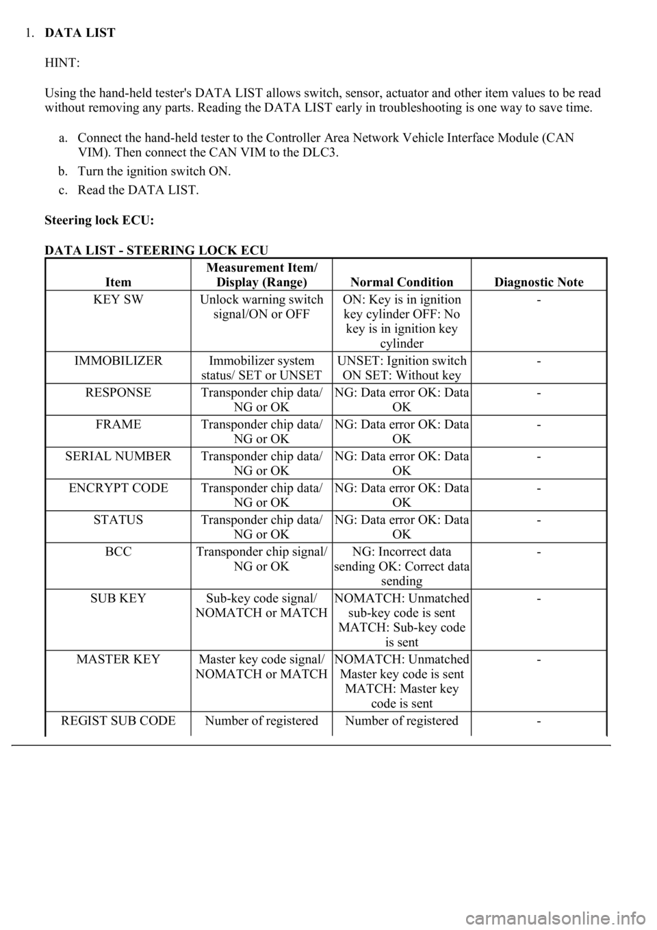
Steering lock ECU:
DATA LIST - STEERING LOCK ECU
Item
Measurement Item/
Display (Range)
Normal ConditionDiagnostic Note
KEY SWUnlock warning switch
signal/ON or OFFON: Key is in ignition
key cylinder OFF: No
key is in ignition key
cylinder-
IMMOBILIZERImmobilizer system
status/ SET or UNSETUNSET: Ignition switch
ON SET: Without key-
RESPONSETransponder chip data/
NG or OKNG: Data error OK: Data
OK-
FRAMETransponder chip data/
NG or OKNG: Data error OK: Data
OK-
SERIAL NUMBERTransponder chip data/
NG or OKNG: Data error OK: Data
OK-
ENCRYPT CODETransponder chip data/
NG or OKNG: Data error OK: Data
OK-
STATUSTransponder chip data/
NG or OKNG: Data error OK: Data
OK-
BCCTransponder chip signal/
NG or OKNG: Incorrect data
sending OK: Correct data
sending-
SUB KEYSub-key code signal/
NOMATCH or MATCHNOMATCH: Unmatched
sub-key code is sent
MATCH: Sub-key code
is sent-
MASTER KEYMaster key code signal/
NOMATCH or MATCHNOMATCH: Unmatched
Master key code is sent
MATCH: Master key
code is sent-
REGIST SUB CODENumber of registered Number of registered -