LEXUS LS430 2003 Factory Repair Manual
LS430 2003
LEXUS
LEXUS
https://www.carmanualsonline.info/img/36/57050/w960_57050-0.png
LEXUS LS430 2003 Factory Repair Manual
Page 2045 of 4500
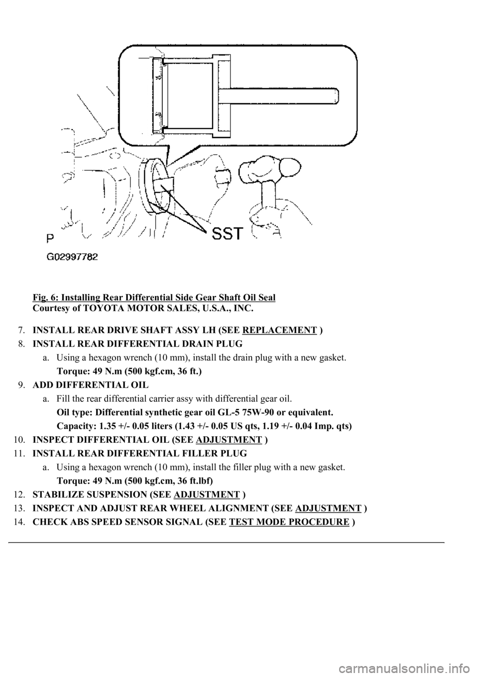
Fig. 6: Installing Rear Differential Side Gear Shaft Oil Seal
Courtesy of TOYOTA MOTOR SALES, U.S.A., INC.
7.INSTALL REAR DRIVE SHAFT ASSY LH (SEE REPLACEMENT
)
8.INSTALL REAR DIFFERENTIAL DRAIN PLUG
a. Using a hexagon wrench (10 mm), install the drain plug with a new gasket.
Torque: 49 N.m (500 kgf.cm, 36 ft.)
9.ADD DIFFERENTIAL OIL
a. Fill the rear differential carrier assy with differential gear oil.
Oil type: Differential synthetic gear oil GL-5 75W-90 or equivalent.
<00260044005300440046004c0057005c001d000300140011001600180003000e00120010000300130011001300180003004f004c00570048005500560003000b00140011001700160003000e00120010000300130011001300180003003800360003005400
570056000f0003001400110014001c0003000e001200100003[0.04 Imp. qts)
10.INSPECT DIFFERENTIAL OIL (SEE ADJUSTMENT
)
11.INSTALL REAR DIFFERENTIAL FILLER PLUG
a. Using a hexagon wrench (10 mm), install the filler plug with a new gasket.
Torque: 49 N.m (500 kgf.cm, 36 ft.lbf)
12.STABILIZE SUSPENSION (SEE ADJUSTMENT
)
13.INSPECT AND ADJUST REAR WHEEL ALIGNMENT (SEE ADJUSTMENT
)
14.CHECK ABS SPEED SENSOR SIGNAL (SEE TEST MODE PROCEDURE
)
Page 2046 of 4500
OVERHAUL
HINT:
See COMPONENTS
1.REMOVE REAR WHEEL
2.REMOVE EXHAUST PIPE ASSY (SEE REPLACEMENT
)
3.REMOVE FRONT FLOOR HEAT INSULATOR NO.1 (SEE OVERHAUL
)
4.REMOVE PROPELLER SHAFT HEAT INSULATOR (SEE OVERHAUL
)
5.REMOVE PROPELLER W/CENTER BEARING SHAFT ASSY (SEE OVERHAUL
)
6.REMOVE REAR DIFFERENTIAL FILLER PLUG
a. Using a hexagon wrench (10 mm), remove the filler plug and gasket.
7.REMOVE REAR DIFFERENTIAL DRAIN PLUG
a. Using a hexagon wrench (10 mm), remove the drain plug and gasket.
b. Drain the differential oil.
8.REMOVE REAR DRIVE SHAFT ASSY LH (SEE REPLACEMENT
)
9.REMOVE REAR DRIVE SHAFT ASSY RH
HINT:
Removal procedure of the RH side is the same as that of the LH side.
10.REMOVE STABILIZER BAR REAR (SEE REPLACEMENT
)
HINT:
Perform this procedure only when the rear differential mount cushion should be changed.
11.REMOVE HEIGHT CONTROL VALVE SUB-ASSY NO.2 (W/ AIR SUSPENSION) (SEE
REPLACEMENT
)
HINT:
Perform this procedure only when the rear differential mount cushion should be changed.
12.REMOVE DIFFERENTIAL CARRIER ASSY REAR
a. Support the differential carrier with a jack and wooden block.
Page 2047 of 4500
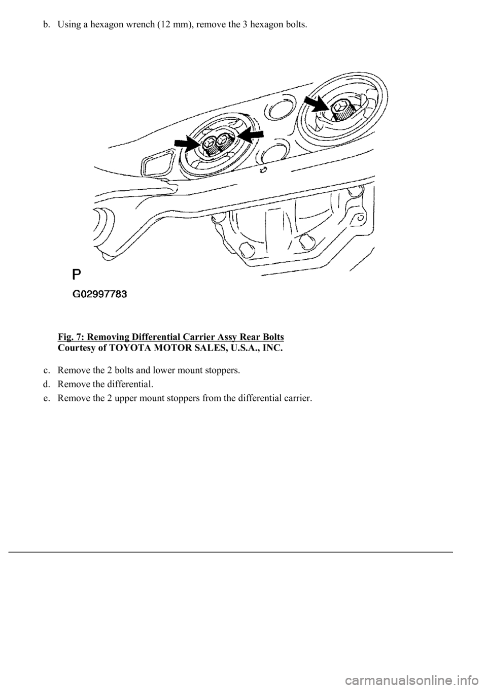
b. Using a hexagon wrench (12 mm), remove the 3 hexagon bolts.
Fig. 7: Removing Differential Carrier Assy Rear Bolts
Courtesy of TOYOTA MOTOR SALES, U.S.A., INC.
c. Remove the 2 bolts and lower mount stoppers.
d. Remove the differential.
e. Remove the 2 upper mount stoppers from the differential carrier.
Page 2051 of 4500
Courtesy of TOYOTA MOTOR SALES, U.S.A., INC.
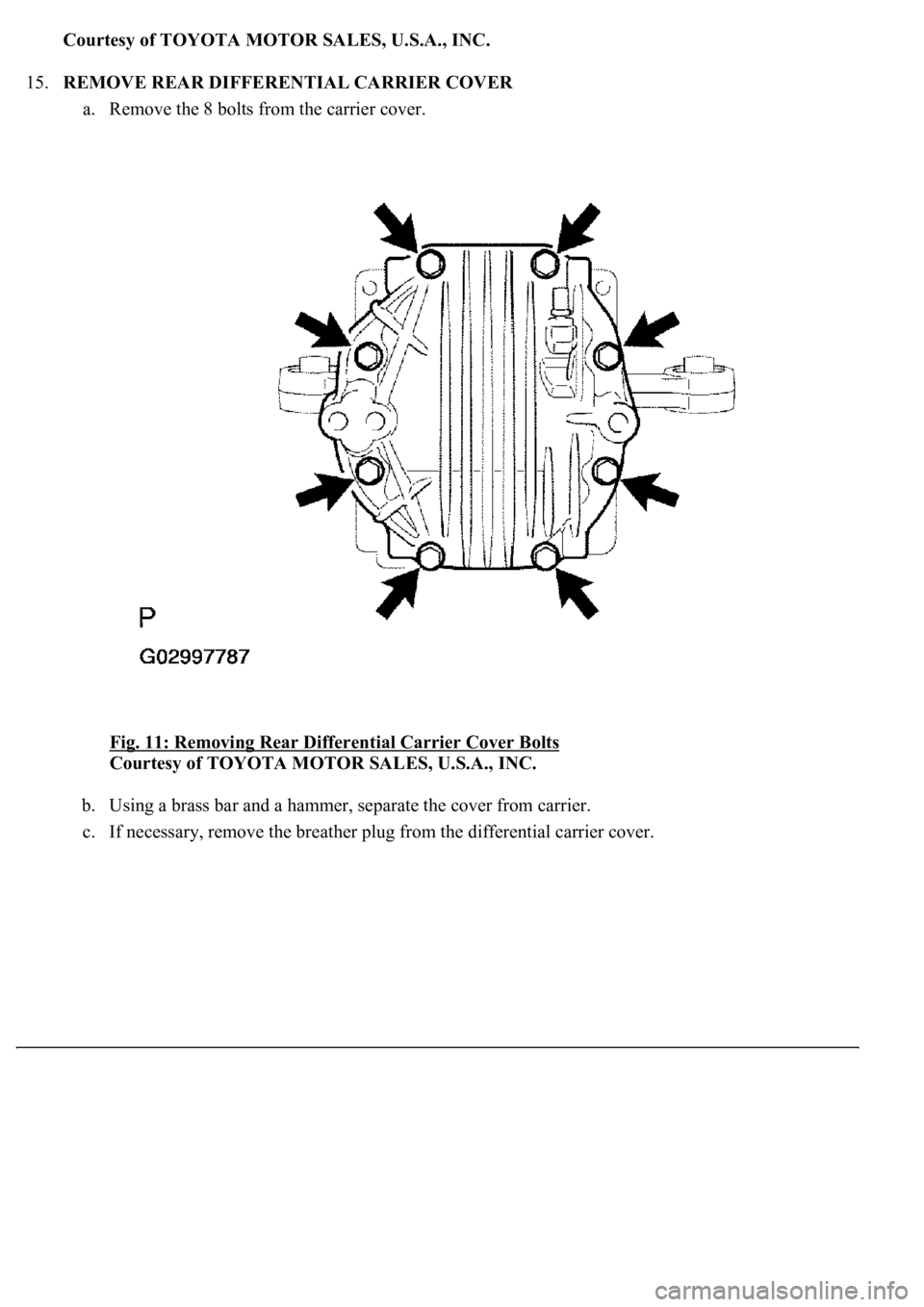
15.REMOVE REAR DIFFERENTIAL CARRIER COVER
a. Remove the 8 bolts from the carrier cover.
Fig. 11: Removing Rear Differential Carrier Cover Bolts
Courtesy of TOYOTA MOTOR SALES, U.S.A., INC.
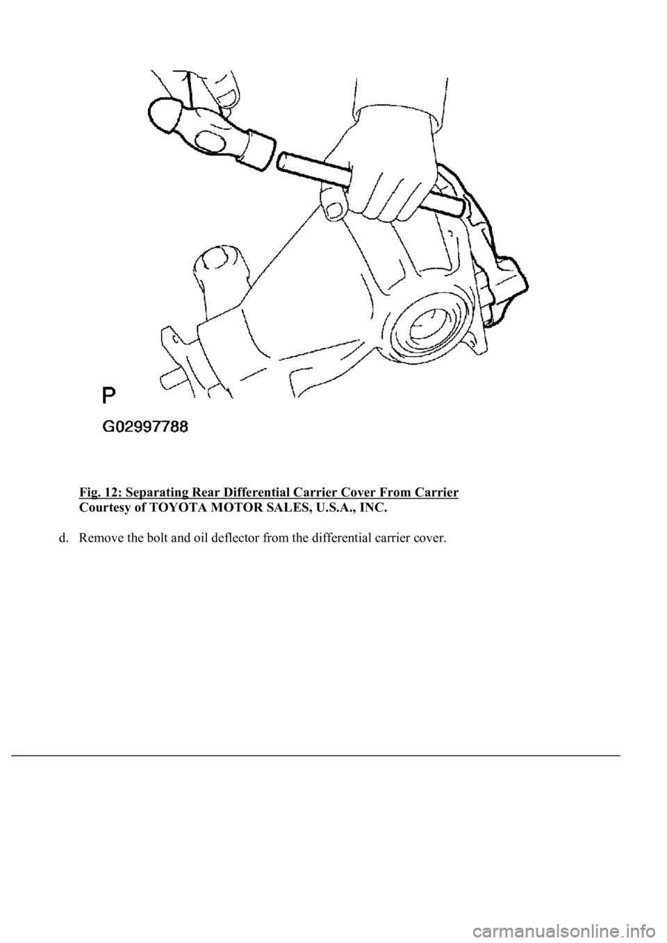
b. Using a brass bar and a hammer, separate the cover from carrier.
c. If necessar
y, remove the breather plug from the differential carrier cover.
Page 2052 of 4500
Fig. 12: Separating Rear Differential Carrier Cover From Carrier
Courtesy of TOYOTA MOTOR SALES, U.S.A., INC.
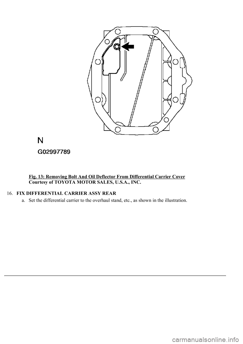
d. Remove the bolt and oil deflector from the differential carrier cover.
Page 2053 of 4500
Fig. 13: Removing Bolt And Oil Deflector From Differential Carrier Cover
Courtesy of TOYOTA MOTOR SALES, U.S.A., INC.
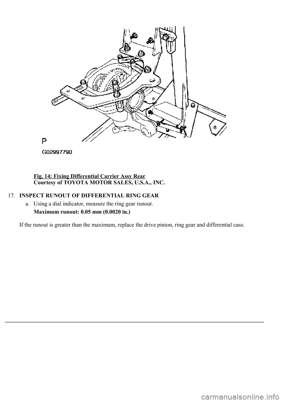
16.FIX DIFFERENTIAL CARRIER ASSY REAR
a. Set the differential carrier to the overhaul stand, etc., as shown in the illustration.
Page 2054 of 4500
Fig. 14: Fixing Differential Carrier Assy Rear
Courtesy of TOYOTA MOTOR SALES, U.S.A., INC.
17.INSPECT RUNOUT OF DIFFERENTIAL RING GEAR
a. Using a dial indicator, measure the ring gear runout.
Maximum runout: 0.05 mm (0.0020 in.)
If the runout is
greater than the maximum, replace the drive pinion, ring gear and differential case.
Page 2064 of 4500
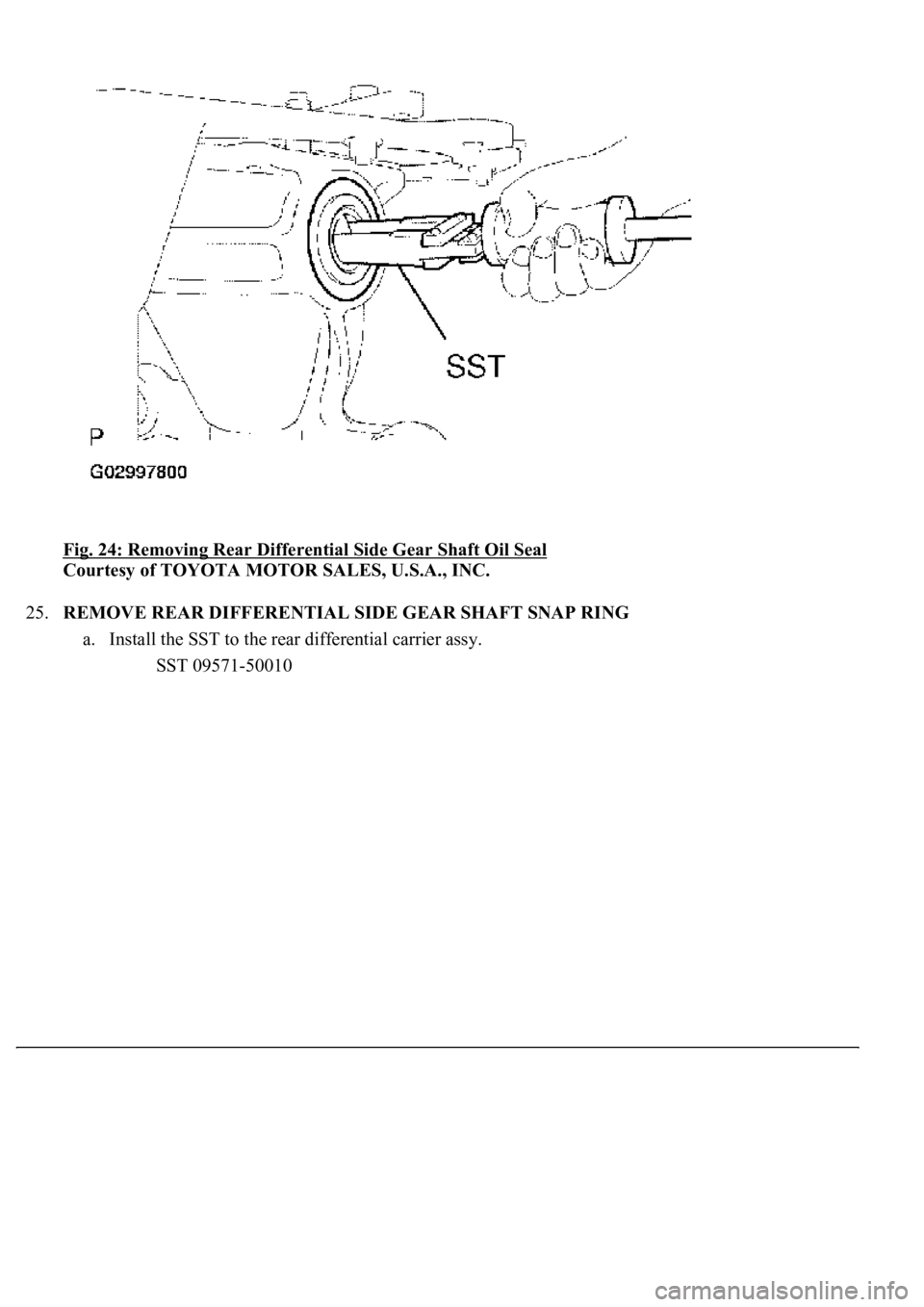
Fig. 24: Removing Rear Differential Side Gear Shaft Oil Seal
Courtesy of TOYOTA MOTOR SALES, U.S.A., INC.
25.REMOVE REAR DIFFERENTIAL SIDE GEAR SHAFT SNAP RING
a. Install the SST to the rear differential carrier assy.
SST 09571-50010
Page 2065 of 4500
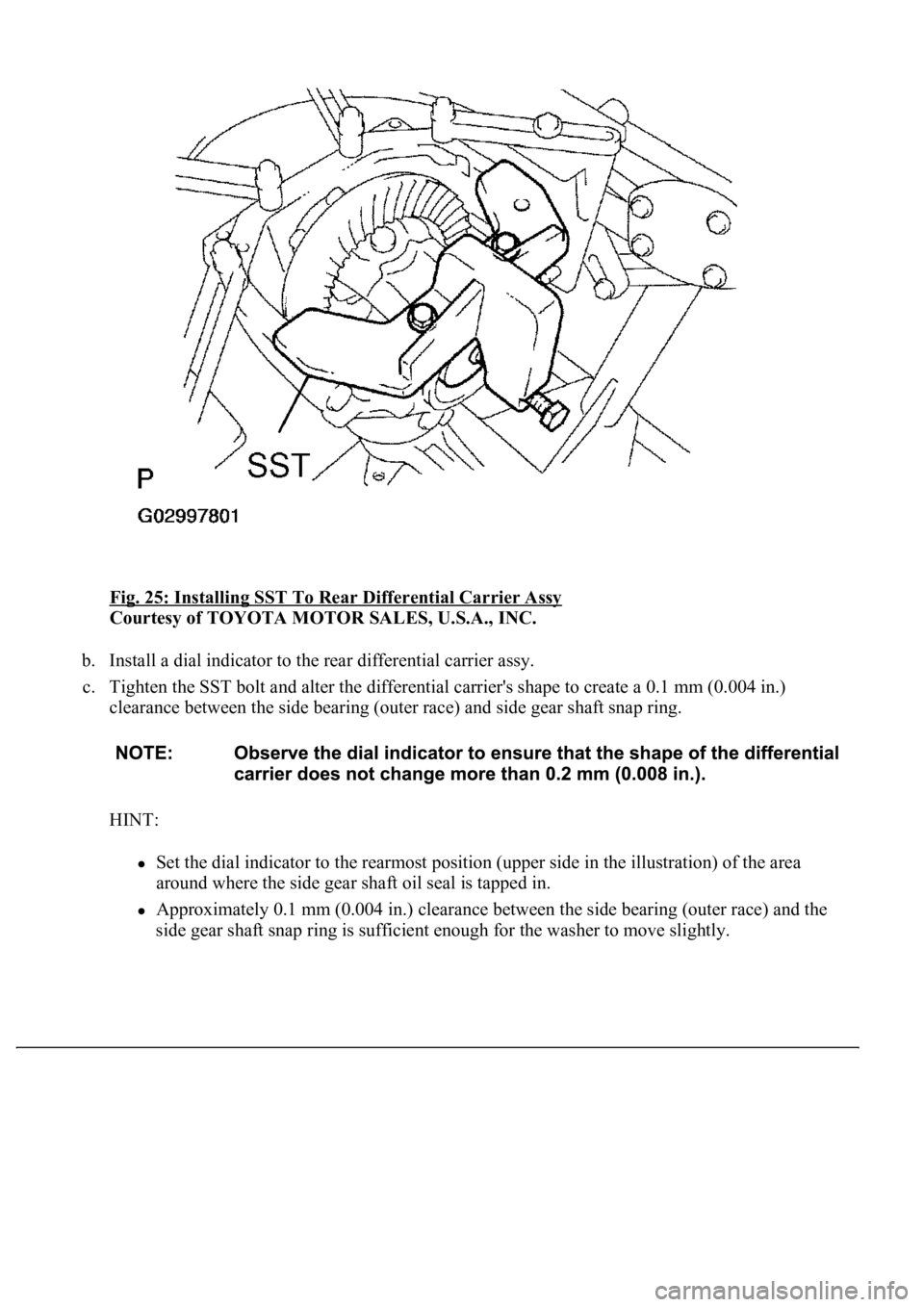
Fig. 25: Installing SST To Rear Differential Carrier Assy
Courtesy of TOYOTA MOTOR SALES, U.S.A., INC.
b. Install a dial indicator to the rear differential carrier assy.
c. Tighten the SST bolt and alter the differential carrier's shape to create a 0.1 mm (0.004 in.)
clearance between the side bearing (outer race) and side gear shaft snap ring.
HINT:
Set the dial indicator to the rearmost position (upper side in the illustration) of the area
around where the side gear shaft oil seal is tapped in.
Approximately 0.1 mm (0.004 in.) clearance between the side bearing (outer race) and the
side
gear shaft snap ring is sufficient enough for the washer to move slightly.
Page 2076 of 4500
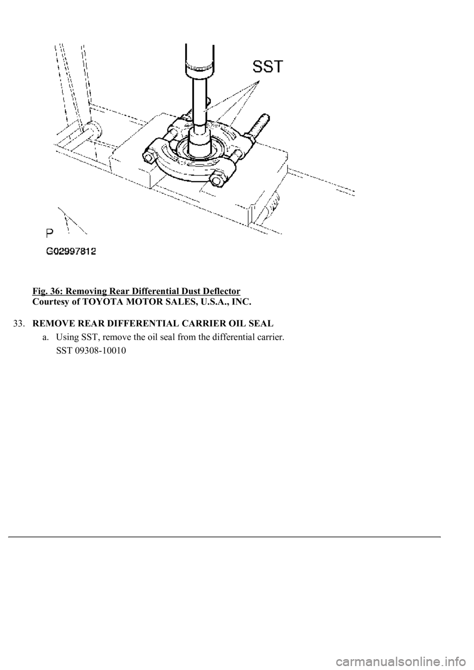
Fig. 36: Removing Rear Differential Dust Deflector
Courtesy of TOYOTA MOTOR SALES, U.S.A., INC.
33.REMOVE REAR DIFFERENTIAL CARRIER OIL SEAL
a. Using SST, remove the oil seal from the differential carrier.
SST 09308-10010