Vvt LEXUS LS430 2003 Factory Repair Manual
[x] Cancel search | Manufacturer: LEXUS, Model Year: 2003, Model line: LS430, Model: LEXUS LS430 2003Pages: 4500, PDF Size: 87.45 MB
Page 2633 of 4500
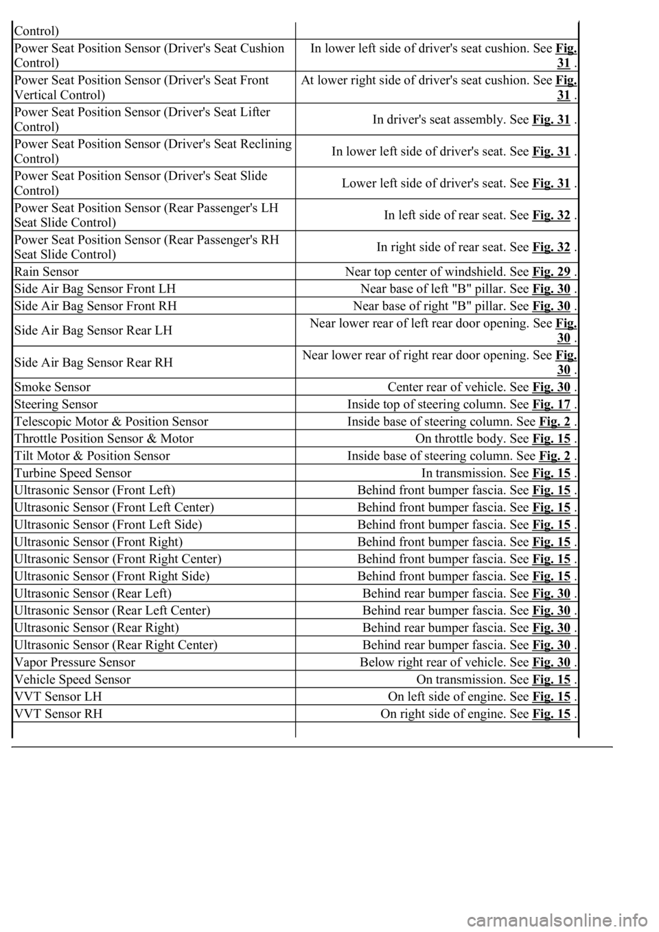
Control)
Power Seat Position Sensor (Driver's Seat Cushion
Control)In lower left side of driver's seat cushion. See Fig.
31 .
Power Seat Position Sensor (Driver's Seat Front
Vertical Control)At lower right side of driver's seat cushion. See Fig.
31 .
Power Seat Position Sensor (Driver's Seat Lifter
Control)In driver's seat assembly. See Fig. 31 .
Power Seat Position Sensor (Driver's Seat Reclining
Control)In lower left side of driver's seat. See Fig. 31 .
Power Seat Position Sensor (Driver's Seat Slide
Control)Lower left side of driver's seat. See Fig. 31 .
Power Seat Position Sensor (Rear Passenger's LH
Seat Slide Control)In left side of rear seat. See Fig. 32 .
Power Seat Position Sensor (Rear Passenger's RH
Seat Slide Control)In right side of rear seat. See Fig. 32 .
Rain SensorNear top center of windshield. See Fig. 29 .
Side Air Bag Sensor Front LHNear base of left "B" pillar. See Fig. 30 .
Side Air Bag Sensor Front RHNear base of right "B" pillar. See Fig. 30 .
Side Air Bag Sensor Rear LHNear lower rear of left rear door opening. See Fig.
30 .
Side Air Bag Sensor Rear RHNear lower rear of right rear door opening. See Fig.
30 .
Smoke SensorCenter rear of vehicle. See Fig. 30 .
Steering SensorInside top of steering column. See Fig. 17 .
Telescopic Motor & Position SensorInside base of steering column. See Fig. 2 .
Throttle Position Sensor & MotorOn throttle body. See Fig. 15 .
Tilt Motor & Position SensorInside base of steering column. See Fig. 2 .
Turbine Speed SensorIn transmission. See Fig. 15 .
Ultrasonic Sensor (Front Left)Behind front bumper fascia. See Fig. 15 .
Ultrasonic Sensor (Front Left Center)Behind front bumper fascia. See Fig. 15 .
Ultrasonic Sensor (Front Left Side)Behind front bumper fascia. See Fig. 15 .
Ultrasonic Sensor (Front Right)Behind front bumper fascia. See Fig. 15 .
Ultrasonic Sensor (Front Right Center)Behind front bumper fascia. See Fig. 15 .
Ultrasonic Sensor (Front Right Side)Behind front bumper fascia. See Fig. 15 .
Ultrasonic Sensor (Rear Left)Behind rear bumper fascia. See Fig. 30 .
Ultrasonic Sensor (Rear Left Center)Behind rear bumper fascia. See Fig. 30 .
Ultrasonic Sensor (Rear Right)Behind rear bumper fascia. See Fig. 30 .
Ultrasonic Sensor (Rear Right Center)Behind rear bumper fascia. See Fig. 30 .
Vapor Pressure SensorBelow right rear of vehicle. See Fig. 30 .
Vehicle Speed SensorOn transmission. See Fig. 15 .
VVT Sensor LHOn left side of engine. See Fig. 15 .
VVT Sensor RHOn right side of engine. See Fig. 15 .
Page 2669 of 4500
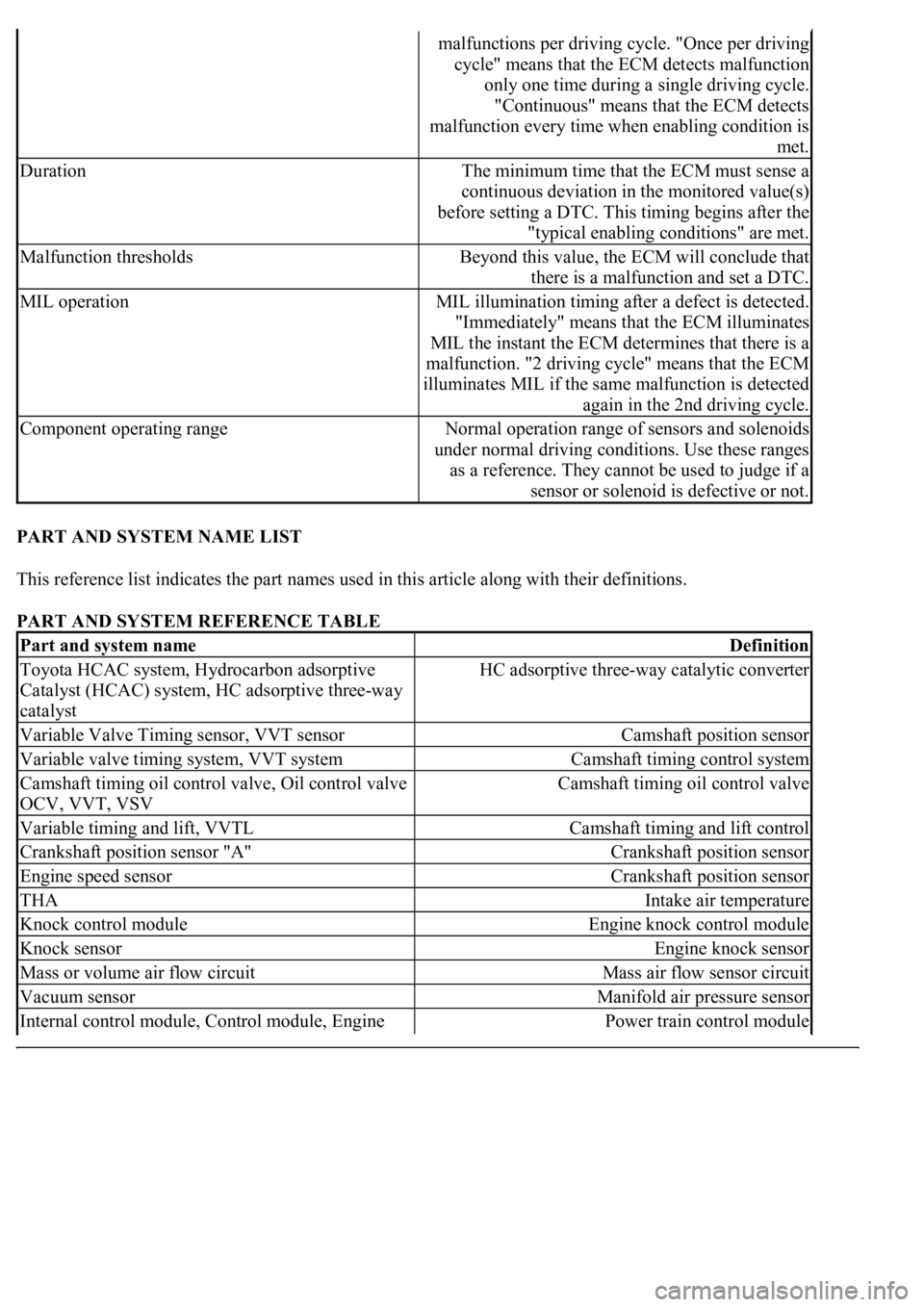
PART AND SYSTEM NAME LIST
This reference list indicates the part names used in this article along with their definitions.
PART AND SYSTEM REFERENCE TABLE
malfunctions per driving cycle. "Once per driving
cycle" means that the ECM detects malfunction
only one time during a single driving cycle.
"Continuous" means that the ECM detects
malfunction every time when enabling condition is
met.
DurationThe minimum time that the ECM must sense a
continuous deviation in the monitored value(s)
before setting a DTC. This timing begins after the
"typical enabling conditions" are met.
Malfunction thresholdsBeyond this value, the ECM will conclude that
there is a malfunction and set a DTC.
MIL operationMIL illumination timing after a defect is detected.
"Immediately" means that the ECM illuminates
MIL the instant the ECM determines that there is a
malfunction. "2 driving cycle" means that the ECM
illuminates MIL if the same malfunction is detected
again in the 2nd driving cycle.
Component operating rangeNormal operation range of sensors and solenoids
under normal driving conditions. Use these ranges
as a reference. They cannot be used to judge if a
sensor or solenoid is defective or not.
Part and system nameDefinition
Toyota HCAC system, Hydrocarbon adsorptive
Catalyst (HCAC) system, HC adsorptive three-way
catalystHC adsorptive three-way catalytic converter
Variable Valve Timing sensor, VVT sensorCamshaft position sensor
Variable valve timing system, VVT systemCamshaft timing control system
Camshaft timing oil control valve, Oil control valve
OCV, VVT, VSVCamshaft timing oil control valve
Variable timing and lift, VVTLCamshaft timing and lift control
Crankshaft position sensor "A"Crankshaft position sensor
Engine speed sensorCrankshaft position sensor
THAIntake air temperature
Knock control moduleEngine knock control module
Knock sensorEngine knock sensor
Mass or volume air flow circuitMass air flow sensor circuit
Vacuum sensorManifold air pressure sensor
Internal control module, Control module, Engine Power train control module
Page 2945 of 4500
Standard: 0.6 to 1.0 V
If the result is not as specified, replace the accelerator pedal position sensor.
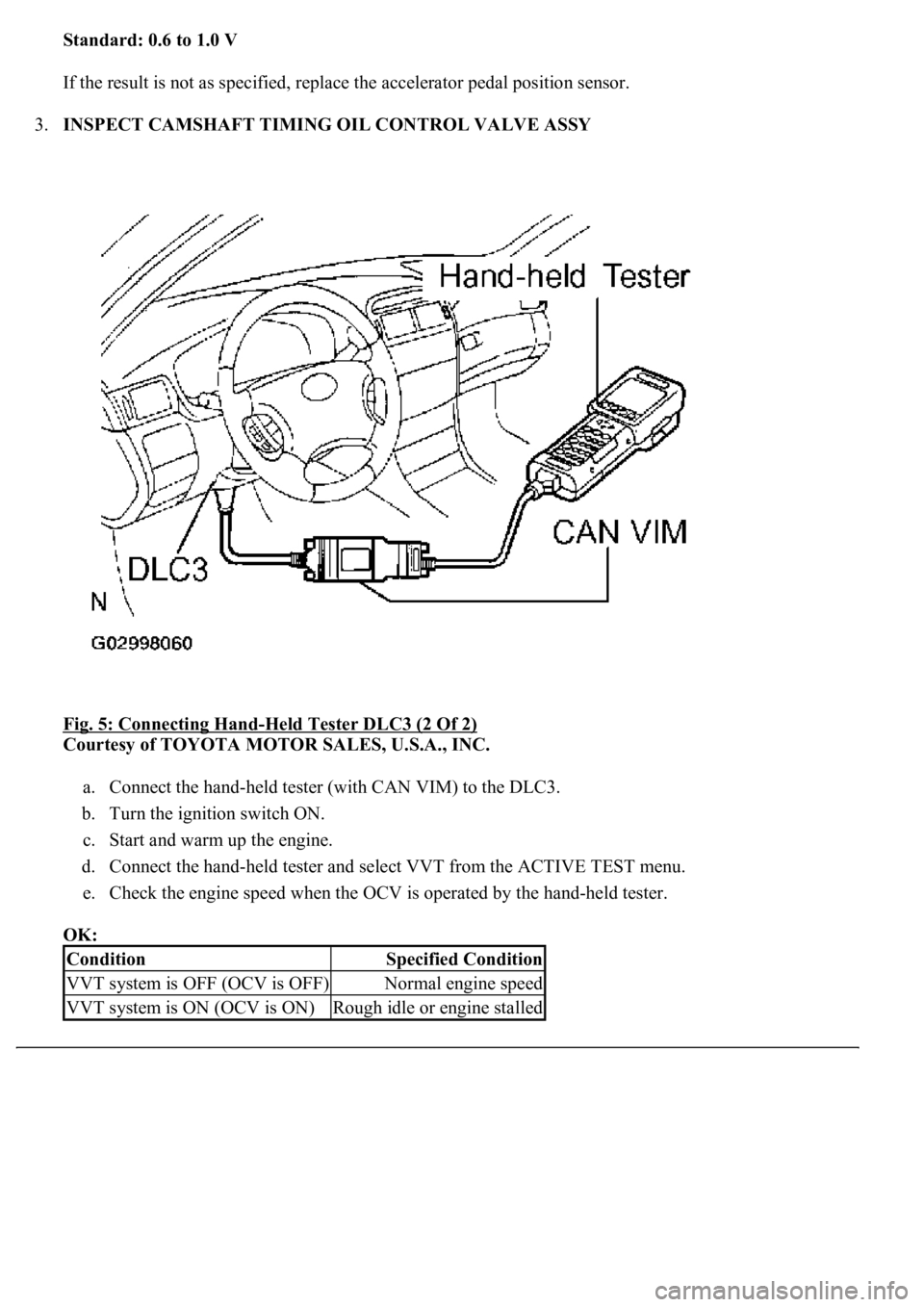
3.INSPECT CAMSHAFT TIMING OIL CONTROL VALVE ASSY
Fig. 5: Connecting Hand
-Held Tester DLC3 (2 Of 2)
Courtesy of TOYOTA MOTOR SALES, U.S.A., INC.
a. Connect the hand-held tester (with CAN VIM) to the DLC3.
b. Turn the ignition switch ON.
c. Start and warm up the engine.
d. Connect the hand-held tester and select VVT from the ACTIVE TEST menu.
e. Check the engine speed when the OCV is operated by the hand-held tester.
OK:
ConditionSpecified Condition
VVT system is OFF (OCV is OFF)Normal engine speed
VVT system is ON (OCV is ON)Rough idle or engine stalled
Page 3327 of 4500
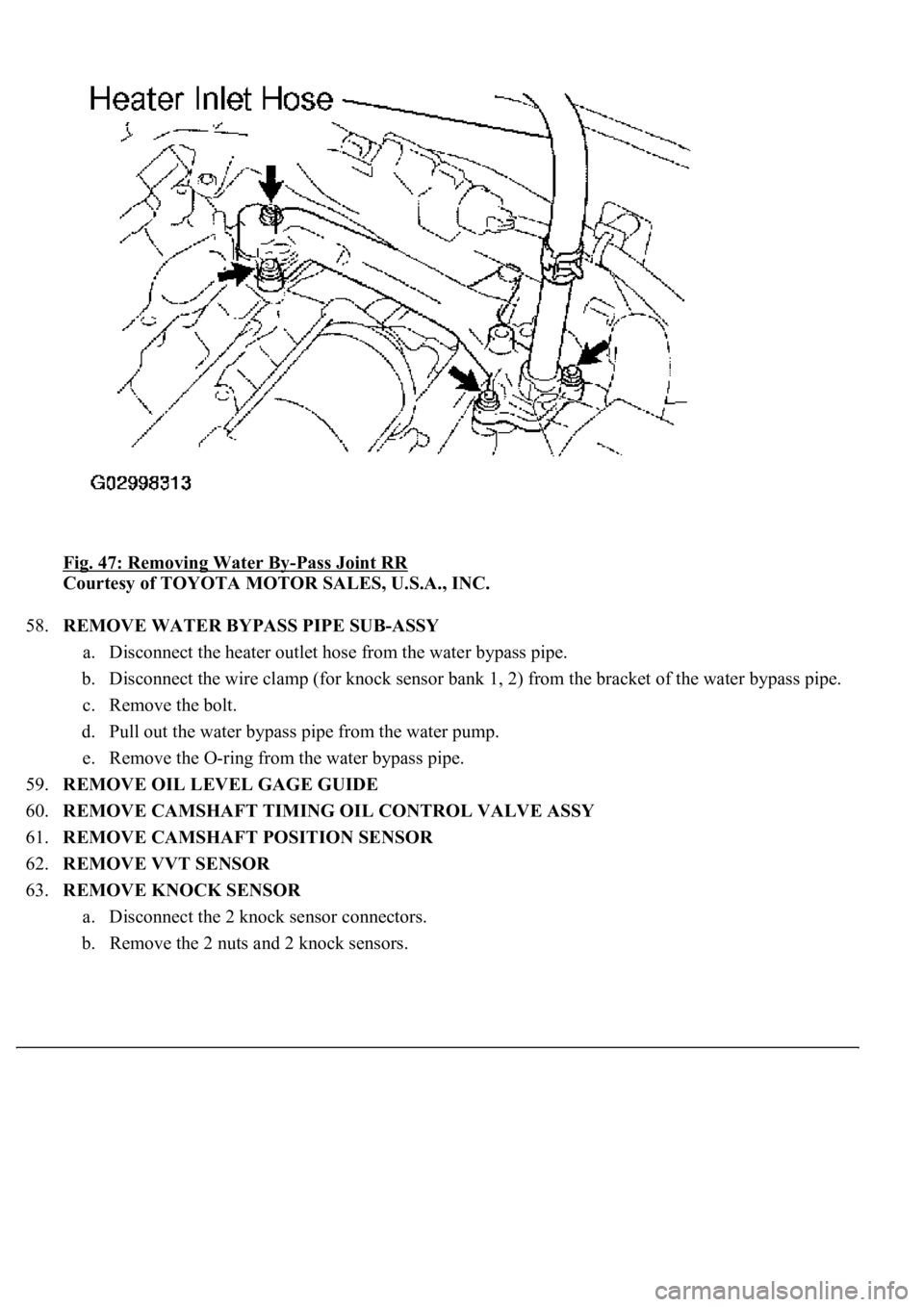
Fig. 47: Removing Water By-Pass Joint RR
Courtesy of TOYOTA MOTOR SALES, U.S.A., INC.
58.REMOVE WATER BYPASS PIPE SUB-ASSY
a. Disconnect the heater outlet hose from the water bypass pipe.
b. Disconnect the wire clamp (for knock sensor bank 1, 2) from the bracket of the water bypass pipe.
c. Remove the bolt.
d. Pull out the water bypass pipe from the water pump.
e. Remove the O-ring from the water bypass pipe.
59.REMOVE OIL LEVEL GAGE GUIDE
60.REMOVE CAMSHAFT TIMING OIL CONTROL VALVE ASSY
61.REMOVE CAMSHAFT POSITION SENSOR
62.REMOVE VVT SENSOR
63.REMOVE KNOCK SENSOR
a. Disconnect the 2 knock sensor connectors.
b. Remove the 2 nuts and 2 knock sensors.
Page 3339 of 4500
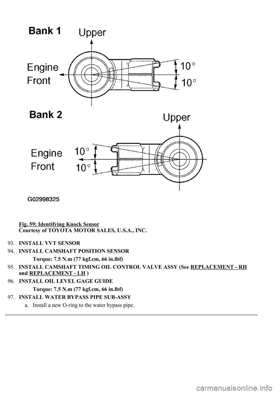
Fig. 59: Identifying Knock Sensor
Courtesy of TOYOTA MOTOR SALES, U.S.A., INC.
93.INSTALL VVT SENSOR
94.INSTALL CAMSHAFT POSITION SENSOR
Torque: 7.5 N.m (77 kgf.cm, 66 in.lbf)
95.INSTALL CAMSHAFT TIMING OIL CONTROL VALVE ASSY (See REPLACEMENT
- RH
and REPLACEMENT
- LH )
96.INSTALL OIL LEVEL GAGE GUIDE
Torque: 7.5 N.m (77 kgf.cm, 66 in.lbf)
97.INSTALL WATER BYPASS PIPE SUB-ASSY
a. Install a new O-rin
g to the water bypass pipe.