compressor pressure LEXUS LS430 2003 Factory Repair Manual
[x] Cancel search | Manufacturer: LEXUS, Model Year: 2003, Model line: LS430, Model: LEXUS LS430 2003Pages: 4500, PDF Size: 87.45 MB
Page 298 of 4500

Courtesy of TOYOTA MOTOR SALES, U.S.A., INC.
NG: REPAIR OR REPLACE HARNESS OR CONNECTOR
OK: REPLACE AIR CONDITIONING AMPLIFIER (SEE REPLACEMENT
)
CIRCUIT DESCRIPTION
The pressure switch sends the appropriate signals to the A/C amplifier when the A/C refrigerant pressure drops
too low or rises too high.
When the A/C amplifier receives these signals, the compressor does not compress refrigerant.
Fig. 75: DTC Detection Item Trouble Area Chart
Courtesy of TOYOTA MOTOR SALES, U.S.A., INC.
WIRING DIAGRAM
Page 2421 of 4500

HVAC DIAGNOSTIC TROUBLE CODE (DTC) IDENTIFICATION
LIGHTING SYSTEM DIAGNOSTIC TROUBLE CODE (DTC) IDENTIFICATION
SENSOR/SWITCH "D"/"E" VOLTAGE
CORRELATION
DTC P2121 THROTTLE/PEDAL POSITION
SENSOR/SWITCH "D" CIRCUIT
RANGE/PERFORMANCE
DTC U0001 HIGH SPEED CAN COMMUNICATION
CIRCUIT
DTCDescription
DTC B1411 ROOM TEMPERATURE SENSOR CIRCUIT
DTC B1412 AMBIENT TEMPERATURE SENSOR CIRCUIT
DTC B1413 EVAPORATOR TEMPERATURE SENSOR CIRCUIT
DTC B1415 AIR DUCT SENSOR CIRCUIT (DRIVER SIDE)
DTC B1416 AIR DUCT SENSOR CIRCUIT (PASSENGER SIDE)
DTC B1418 EMISSION GAS SENSOR CIRCUIT
DTC B1421 SOLAR SENSOR CIRCUIT (PASSENGER SIDE)
DTC B1423 PRESSURE SWITCH CIRCUIT
DTC B1424 SOLAR SENSOR CIRCUIT (DRIVER SIDE)
DTC B1428 REAR SOLAR SENSOR CIRCUIT
DTC B1432 AIR INLET DAMPER POSITION SENSOR CIRCUIT
DTC B1434 MAX COOL DAMPER POSITION SENSOR CIRCUIT (DRIVER SIDE)
DTC B1435 MAX COOL DAMPER POSITION SENSOR CIRCUIT (PASSENGER SIDE)
DTC B1442 AIR INLET DAMPER CONTROL SERVOMOTOR CIRCUIT
DTC B1451 COMPRESSOR SOLENOID CIRCUIT
DTC B1461 EMISSION GAS NOX SENSOR CIRCUIT
DTCDescription
DTC B1244 LIGHT SENSOR CIRCUIT MALFUNCTION
DTC B1268 BACK-UP COMMUNICATION BUS MALFUNCTION
DTC B2402, B2403 TRANSISTOR RELAY OVERLOAD/OVERHEAT MALFUNCTION
DTC B2412, B2413 HEADLIGHT SWIVEL MOTOR LH/RH MALFUNCTION
DTC B2414 STEERING POSITION SENSOR MALFUNCTION
DTC B2415 VEHICLE SPEED SENSOR MALFUNCTION
DTC B2416 HEIGHT CONTROL SENSOR MALFUNCTION
DTC B2417, B2418 HEADLIGHT BEAM LEVEL CONTROL MOTOR LH/RH
MALFUNCTION
Page 3313 of 4500
13.DRAIN AUTOMATIC TRANSMISSION FLUID
14.REMOVE RADIATOR ASSY (See REPLACEMENT
)
15.DISCONNECT FUEL PIPE SUB-ASSY NO.2 (See REPLACEMENT
)
16.REMOVE FAN AND GENERATOR V BELT (See REPLACEMENT
)
17.DISCONNECT ENGINE WIRE
a. Disconnect the engine wire from the ECM box.
b. Remove the nut, and disconnect the generator wire from the generator.
c. Disconnect the wire for generator wire from the wire clamp on generator.
d. Remove the bolt, and disconnect the ground cable from the stay on the generator.
e. Remove the 2 bolts, and disconnect the PS oil hose from the No. 1 oil pan.
f. Remove the bolt, and disconnect the ground strap from the body.
18.DISCONNECT AIR HOSE NO.5
19.DISCONNECT FUEL VAPOR FEED HOSE NO.2
20.DISCONNECT HEATER WATER INLET HOSE A
21.DISCONNECT HEATER WATER OUTLET HOSE A (FROM HEATER UNIT)
22.DISCONNECT VANE PUMP OIL RESERVOIR ASSY
23.DISCONNECT VANE PUMP ASSY
a. Disconnect the 2 PS air hoses.
b. Remove the 2 screws and RH engine under cover.
c. Disconnect the PS oil pressure switch connector.
d. Remove the 2 bolts and nut, and disconnect the pump from the engine.
e. Support the pump securely.
24.DISCONNECT COOLER COMPRESSOR ASSY
a. Disconnect the compressor connector.
b. Disconnect the wire clamp from the wire bracket on the compressor.
c. Remove the bolt, nut and stay.
d. Remove the bolt, and disconnect the wire bracket from the compressor.
e. Remove the bolt, and disconnect the compressor from the engine.
f. Support the cooler compressor securely.
25.REMOVE FRONT FLOOR BRACE CENTER
a. Remove the 4 bolts and brace center.
26.REMOVE EXHAUST PIPE ASSY (See REPLACEMENT
)
27.REMOVE W/ CATALYST CONVERTER ASSY
28.REMOVE FRONT FLOOR HEAT INSULATOR NO.1
29.REMOVE PARKING BRAKE CABLE HEAT INSULATOR
30.REMOVE PROPELLER W/ CENTER BEARING SHAFT ASSY (See OVERHAUL
)
31.REMOVE FLOOR SHIFT GEAR SHIFTING ROD SUB-ASSY
32.REMOVE STEERING SLIDING W/ SHAFT YOKE SUB-ASSY
Page 3359 of 4500
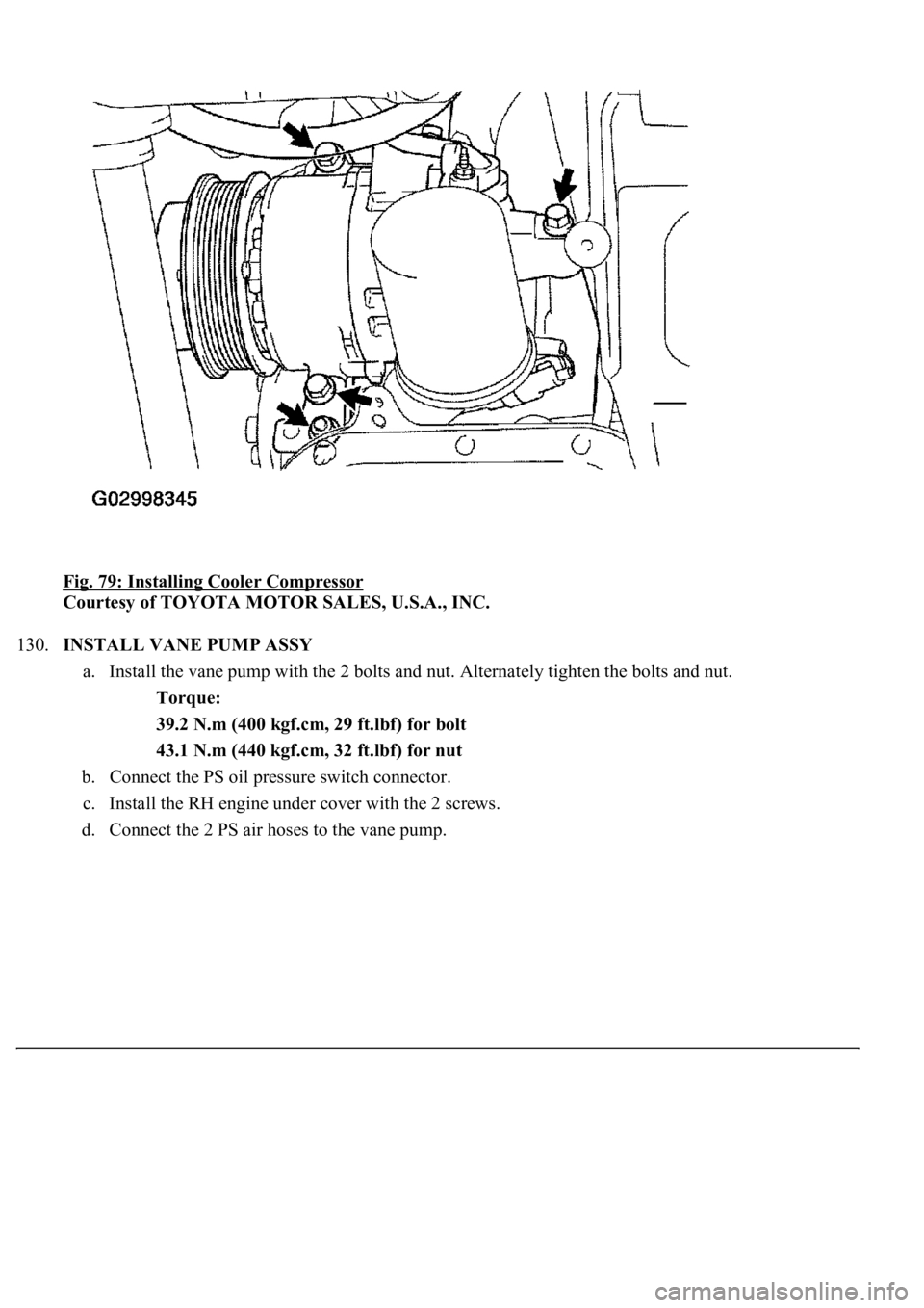
Fig. 79: Installing Cooler Compressor
Courtesy of TOYOTA MOTOR SALES, U.S.A., INC.
130.INSTALL VANE PUMP ASSY
a. Install the vane pump with the 2 bolts and nut. Alternately tighten the bolts and nut.
Torque:
39.2 N.m (400 kgf.cm, 29 ft.lbf) for bolt
43.1 N.m (440 kgf.cm, 32 ft.lbf) for nut
b. Connect the PS oil pressure switch connector.
c. Install the RH engine under cover with the 2 screws.
d. Connect the 2 PS air hoses to the vane pump.
Page 3468 of 4500
Courtesy of TOYOTA MOTOR SALES, U.S.A., INC.
87.INSTALL OIL FILLER CAP SUB-ASSY
88.INSTALL SPARK PLUG
REPLACEMENT
1.DISCONNECT BATTERY NEGATIVE TERMINAL
2.REMOVE AIR CLEANER INLET NO.1
3.DRAIN ENGINE COOLANT
4.REMOVE V-BANK COVER
5.REMOVE INTAKE AIR CONNECTOR PIPE
6.REMOVE ENGINE UNDER COVER NO.1
7.DISCONNECT RADIATOR HOSE NO.1
8.DISCONNECT RADIATOR HOSE NO.2
9.DISCONNECT OIL COOLER INLET TUBE NO.1
10.DISCONNECT OIL COOLER OUTLET TUBE NO.1
11.REMOVE AIR CLEANER ASSY
12.REMOVE RADIATOR ASSY (See REPLACEMENT
13.REMOVE FAN AND GENERATOR V BELT (See REPLACEMENT
)
14.REMOVE VANE PUMP ASSY
a. Remove the 2 bolts, nut and pump.
HINT:
Pump should be removed with the hoses connected and then hang with a rope or wire on the body's side.
15.REMOVE GENERATOR ASSY (See REPLACEMENT
)
16.DISCONNECT COMPRESSOR AND MAGNETIC CLUTCH
HINT:
The cooler compressor with the magnetic clutch should be removed with the low-pressure and high-
pressure hoses connected and then hang with a rope or wire on the body's side.
17.REMOVE TIMING CHAIN OR BELT COVER NO.2
a. Disconnect the 2 PS air hoses from the clamp on the cover.
b. Remove the cap nut, 3 bolts, cover and gasket.
Page 4195 of 4500

compressor burnout may occur. Necessary care should be taken to avoid this.
Fig. 3: Identifying Precaution Operating Compressor
Courtesy of TOYOTA MOTOR SALES, U.S.A., INC.
7.DO NOT OPEN HIGH PRESSURE MANIFOLD VALVE WHILE COMPRESSOR IS
OPERATING
If the high pressure valves are opened, refrigerant flows in the reverse direction and could cause the
charging cylinder to rupture. Open and close only the low pressure valve.
8.BE CAREFUL NOT TO OVERCHARGE SYSTEM WITH REFRIGERANT
If refrigerant is overcharged, it causes problems such as insufficient cooling, poor fuel economy, engine
Page 4207 of 4500
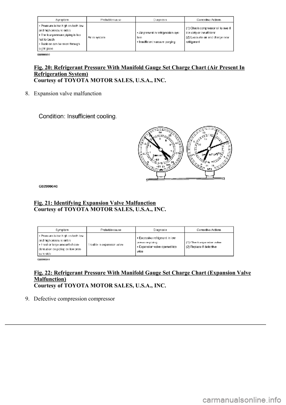
Fig. 20: Refrigerant Pressure With Manifold Gauge Set Charge Chart (Air Present In
Refrigeration System)
Courtesy of TOYOTA MOTOR SALES, U.S.A., INC.
8. Expansion valve malfunction
Fig. 21: Identifying Expansion Valve Malfunction
Courtesy of TOYOTA MOTOR SALES, U.S.A., INC.
Fig. 22: Refrigerant Pressure With Manifold Gauge Set Charge Chart (Expansion Valve
Malfunction)
Courtesy of TOYOTA MOTOR SALES, U.S.A., INC.
9. Defective compression compressor
Page 4210 of 4500
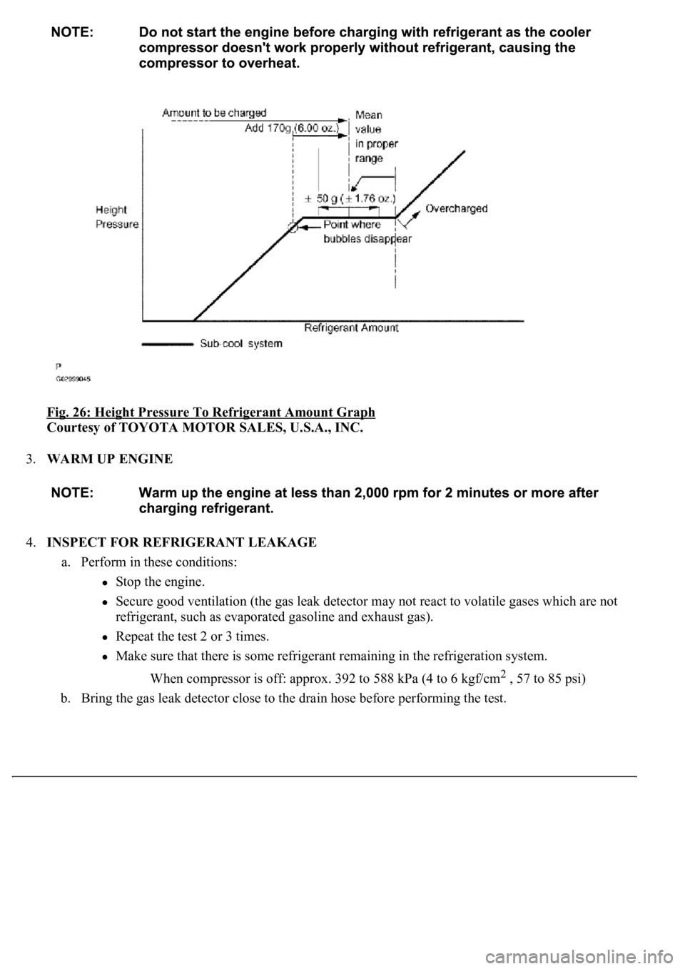
Fig. 26: Height Pressure To Refrigerant Amount Graph
Courtesy of TOYOTA MOTOR SALES, U.S.A., INC.
3.WARM UP ENGINE
4.INSPECT FOR REFRIGERANT LEAKAGE
a. Perform in these conditions:
Stop the engine.
Secure good ventilation (the gas leak detector may not react to volatile gases which are not
refrigerant, such as evaporated gasoline and exhaust gas).
Repeat the test 2 or 3 times.
Make sure that there is some refrigerant remaining in the refrigeration system.
When compressor is off: approx. 392 to 588 kPa (4 to 6 kgf/cm
2 , 57 to 85 psi)
b. Bring the gas leak detector close to the drain hose before performing the test.
Page 4261 of 4500
Fig. 74: Removing Air Inlet Servomotor
Courtesy of TOYOTA MOTOR SALES, U.S.A., INC.
13.REMOVE BLOWER MOTOR ASSY (COOLING UNIT MOTOR SUB-ASSY W/FAN)
a. Remove the 3 screws and blower motor assy (cooling unit motor sub-assy w/fan).
ON-VEHICLE INSPECTION
1.INSPECT COMPRESSOR FOR METALLIC SOUND
a. Check if there is abnormal metallic sound from the compressor when the A/C switch is ON and the
compressor operates.
If abnormal metallic sound is heard, replace the compressor assembly.
2.INSPECT REFRIGERANT PRESSURE (See ON
-VEHICLE INSPECTION )
3.INSPECT FOR LEAKAGE OF REFRIGERANT