wheel LEXUS LS430 2003 Factory Repair Manual
[x] Cancel search | Manufacturer: LEXUS, Model Year: 2003, Model line: LS430, Model: LEXUS LS430 2003Pages: 4500, PDF Size: 87.45 MB
Page 2 of 4500
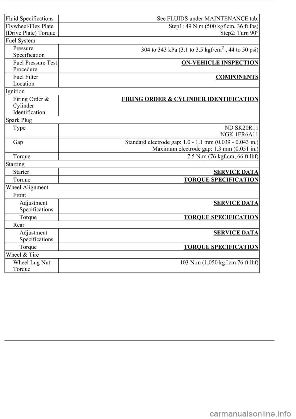
Fluid SpecificationsSee FLUIDS under MAINTENANCE tab.
Flywheel/Flex Plate
(Drive Plate) TorqueStep1: 49 N.m (500 kgf.cm, 36 ft lbs)
Step2: Turn 90°
Fuel System
Pressure
Specification304 to 343 kPa (3.1 to 3.5 kgf/cm2 , 44 to 50 psi)
Fuel Pressure Test
ProcedureON-VEHICLE INSPECTION
Fuel Filter
LocationCOMPONENTS
Ignition
Firing Order &
Cylinder
IdentificationFIRING ORDER & CYLINDER IDENTIFICATION
Spark Plug
TypeND SK20R11
NGK 1FR6A11
GapStandard electrode gap: 1.0 - 1.1 mm (0.039 - 0.043 in.)
Maximum electrode gap: 1.3 mm (0.051 in.)
Torque7.5 N.m (76 kgf.cm, 66 ft.lbf)
Starting
StarterSERVICE DATA
TorqueTORQUE SPECIFICATION
Wheel Alignment
Front
Adjustment
SpecificationsSERVICE DATA
TorqueTORQUE SPECIFICATION
Rear
Adjustment
SpecificationsSERVICE DATA
TorqueTORQUE SPECIFICATION
Wheel & Tire
Wheel Lug Nut
Torque103 N.m (1,050 kgf.cm 76 ft.lbf)
Page 6 of 4500
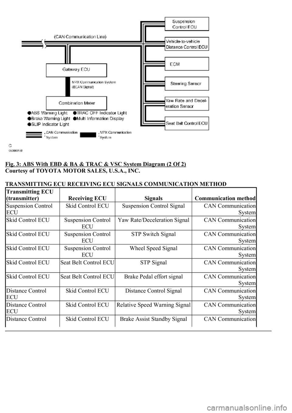
Fig. 3: ABS With EBD & BA & TRAC & VSC System Diagram (2 Of 2)
Courtesy of TOYOTA MOTOR SALES, U.S.A., INC.
TRANSMITTING ECU RECEIVING ECU SIGNALS COMMUNICATION METHOD
Transmitting ECU
(transmitter)
Receiving ECUSignalsCommunication method
Suspension Control
ECUSkid Control ECUSuspension Control SignalCAN Communication
System
Skid Control ECUSuspension Control
ECUYaw Rate/Deceleration SignalCAN Communication
System
Skid Control ECUSuspension Control
ECUSTP Switch SignalCAN Communication
System
Skid Control ECUSuspension Control
ECUWheel Speed SignalCAN Communication
System
Skid Control ECUSeat Belt Control ECUSTP SignalCAN Communication
System
Skid Control ECUSeat Belt Control ECUBrake Pedal effort signalCAN Communication
System
Distance Control
ECUSkid Control ECUDistance Control SignalCAN Communication
System
Distance Control
ECUSkid Control ECURelative Speed Warning SignalCAN Communication
System
Distance Control Skid Control ECUBrake Assist Standby SignalCAN Communication
Page 7 of 4500
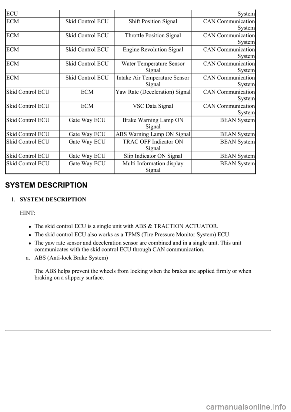
1.SYSTEM DESCRIPTION
HINT:
The skid control ECU is a single unit with ABS & TRACTION ACTUATOR.
The skid control ECU also works as a TPMS (Tire Pressure Monitor System) ECU.
The yaw rate sensor and deceleration sensor are combined and in a single unit. This unit
communicates with the skid control ECU through CAN communication.
a. ABS (Anti-lock Brake System)
The ABS helps prevent the wheels from locking when the brakes are applied firmly or when
braking on a slippery surface.
ECUSystem
ECMSkid Control ECUShift Position SignalCAN Communication
System
ECMSkid Control ECUThrottle Position SignalCAN Communication
System
ECMSkid Control ECUEngine Revolution SignalCAN Communication
System
ECMSkid Control ECUWater Temperature Sensor
SignalCAN Communication
System
ECMSkid Control ECUIntake Air Temperature Sensor
SignalCAN Communication
System
Skid Control ECUECMYaw Rate (Deceleration) SignalCAN Communication
System
Skid Control ECUECMVSC Data SignalCAN Communication
System
Skid Control ECUGate Way ECUBrake Warning Lamp ON
SignalBEAN System
Skid Control ECUGate Way ECUABS Warning Lamp ON SignalBEAN System
Skid Control ECUGate Way ECUTRAC OFF Indicator ON
SignalBEAN System
Skid Control ECUGate Way ECUSlip Indicator ON SignalBEAN System
Skid Control ECUGate Way ECUMulti Information display
SignalBEAN System
Page 8 of 4500
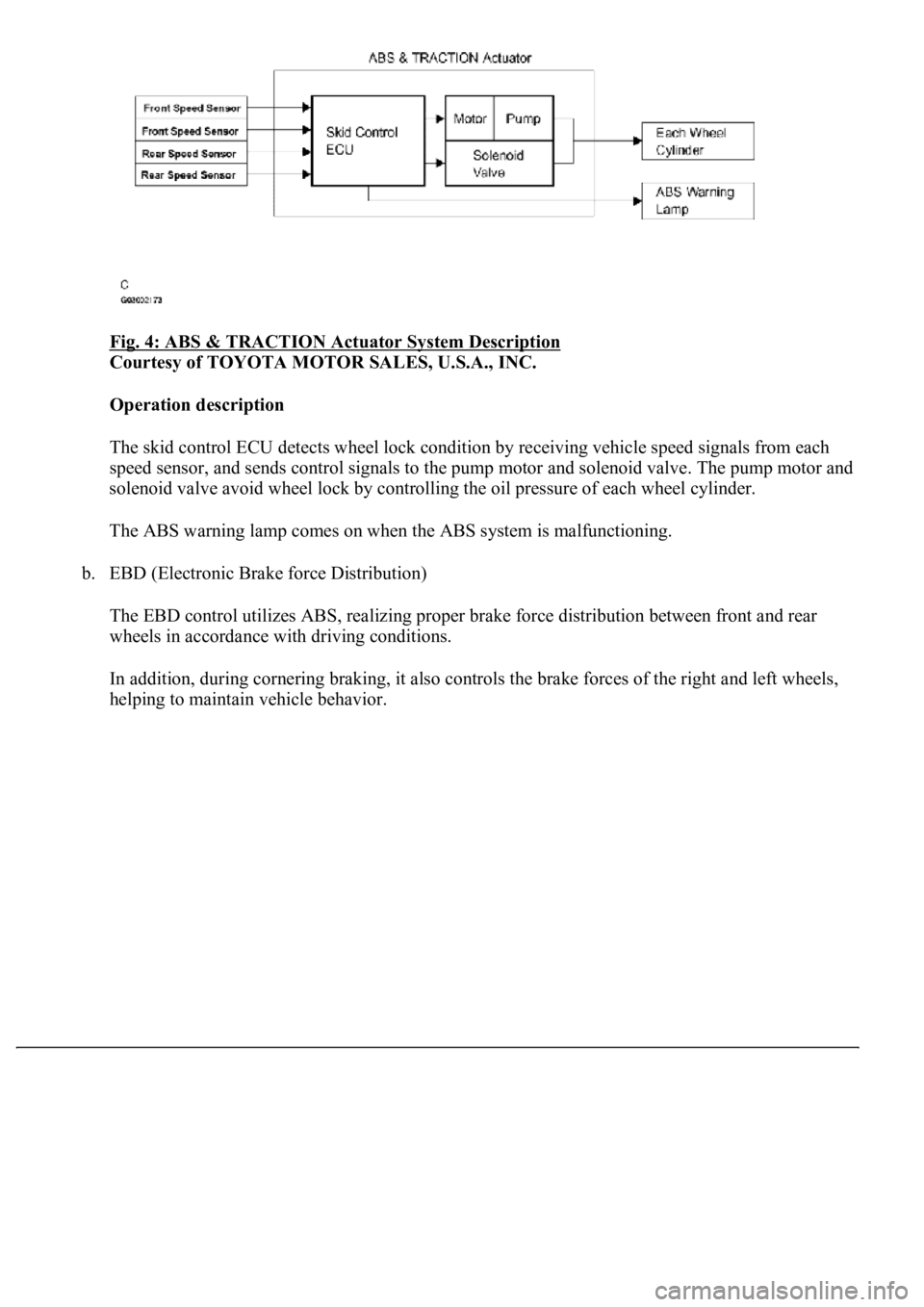
Fig. 4: ABS & TRACTION Actuator System Description
Courtesy of TOYOTA MOTOR SALES, U.S.A., INC.
Operation description
The skid control ECU detects wheel lock condition by receiving vehicle speed signals from each
<005600530048004800470003005600480051005600520055000f00030044005100470003005600480051004700560003004600520051005700550052004f00030056004c004a00510044004f005600030057005200030057004b0048000300530058005000
53000300500052005700520055000300440051004700030056[olenoid valve. The pump motor and
solenoid valve avoid wheel lock by controlling the oil pressure of each wheel cylinder.
The ABS warning lamp comes on when the ABS system is malfunctioning.
b. EBD (Electronic Brake force Distribution)
The EBD control utilizes ABS, realizing proper brake force distribution between front and rear
wheels in accordance with driving conditions.
In addition, during cornering braking, it also controls the brake forces of the right and left wheels,
helping to maintain vehicle behavior.
Page 9 of 4500
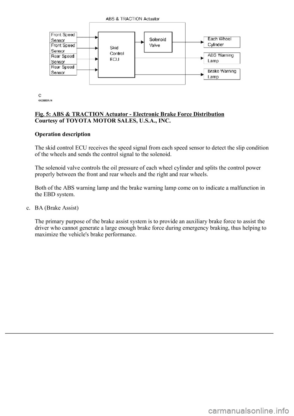
Fig. 5: ABS & TRACTION Actuator - Electronic Brake Force Distribution
Courtesy of TOYOTA MOTOR SALES, U.S.A., INC.
Operation description
The skid control ECU receives the speed signal from each speed sensor to detect the slip condition
<0052004900030057004b00480003005a004b00480048004f0056000300440051004700030056004800510047005600030057004b00480003004600520051005700550052004f00030056004c004a00510044004f00030057005200030057004b0048000300
560052004f004800510052004c004700110003[
The solenoid valve controls the oil pressure of each wheel cylinder and splits the control power
properly between the front and rear wheels and the right and rear wheels.
Both of the ABS warning lamp and the brake warning lamp come on to indicate a malfunction in
the EBD system.
c. BA (Brake Assist)
The primary purpose of the brake assist system is to provide an auxiliary brake force to assist the
driver who cannot generate a large enough brake force during emergency braking, thus helping to
maximize the vehicle's brake performance.
Page 10 of 4500
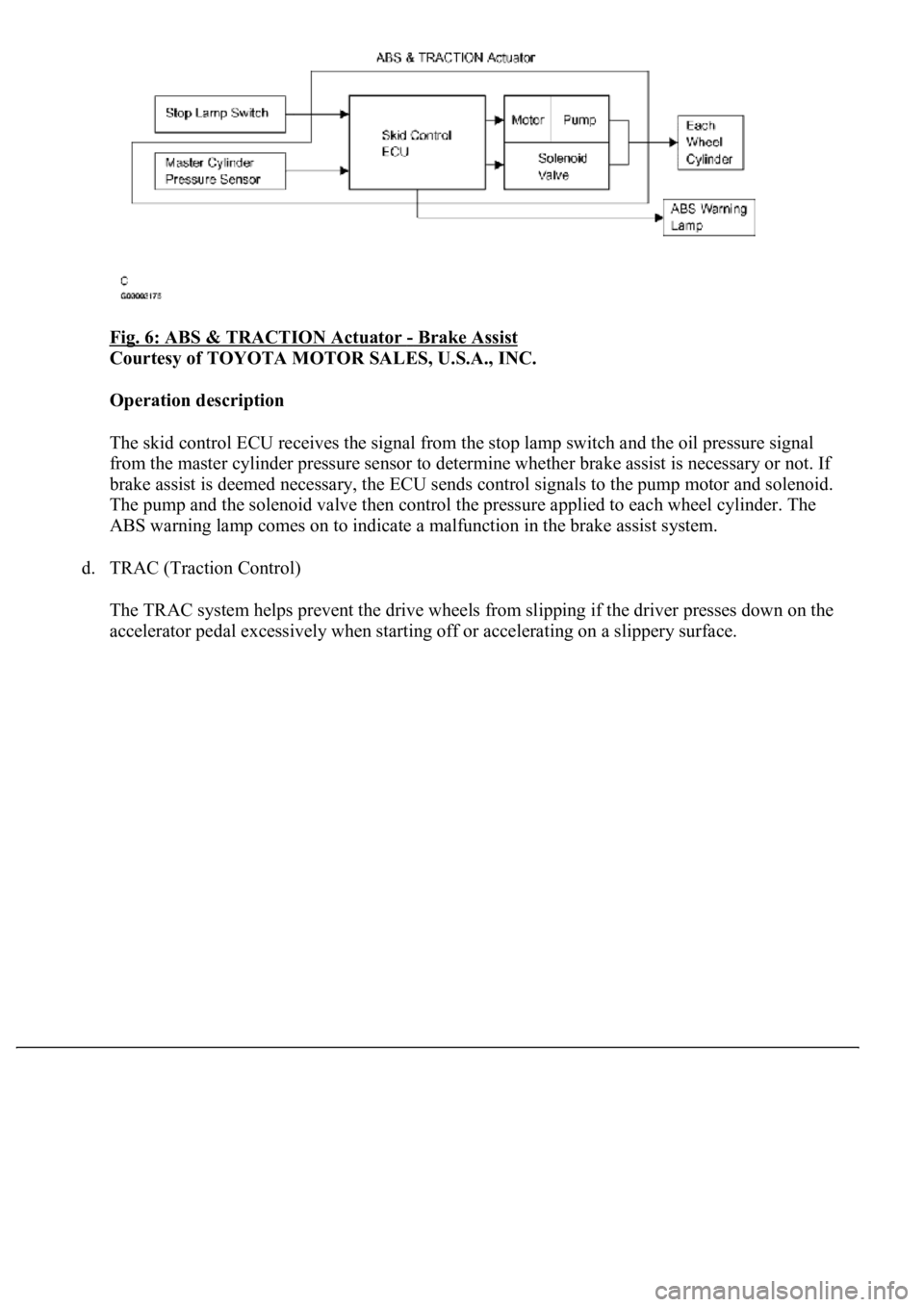
Fig. 6: ABS & TRACTION Actuator - Brake Assist
Courtesy of TOYOTA MOTOR SALES, U.S.A., INC.
Operation description
The skid control ECU receives the signal from the stop lamp switch and the oil pressure signal
from the master cylinder pressure sensor to determine whether brake assist is necessary or not. If
brake assist is deemed necessary, the ECU sends control signals to the pump motor and solenoid.
The pump and the solenoid valve then control the pressure applied to each wheel cylinder. The
ABS warning lamp comes on to indicate a malfunction in the brake assist system.
d. TRAC (Traction Control)
The TRAC system helps prevent the drive wheels from slipping if the driver presses down on the
accelerator pedal excessivel
y when starting off or accelerating on a slippery surface.
Page 11 of 4500
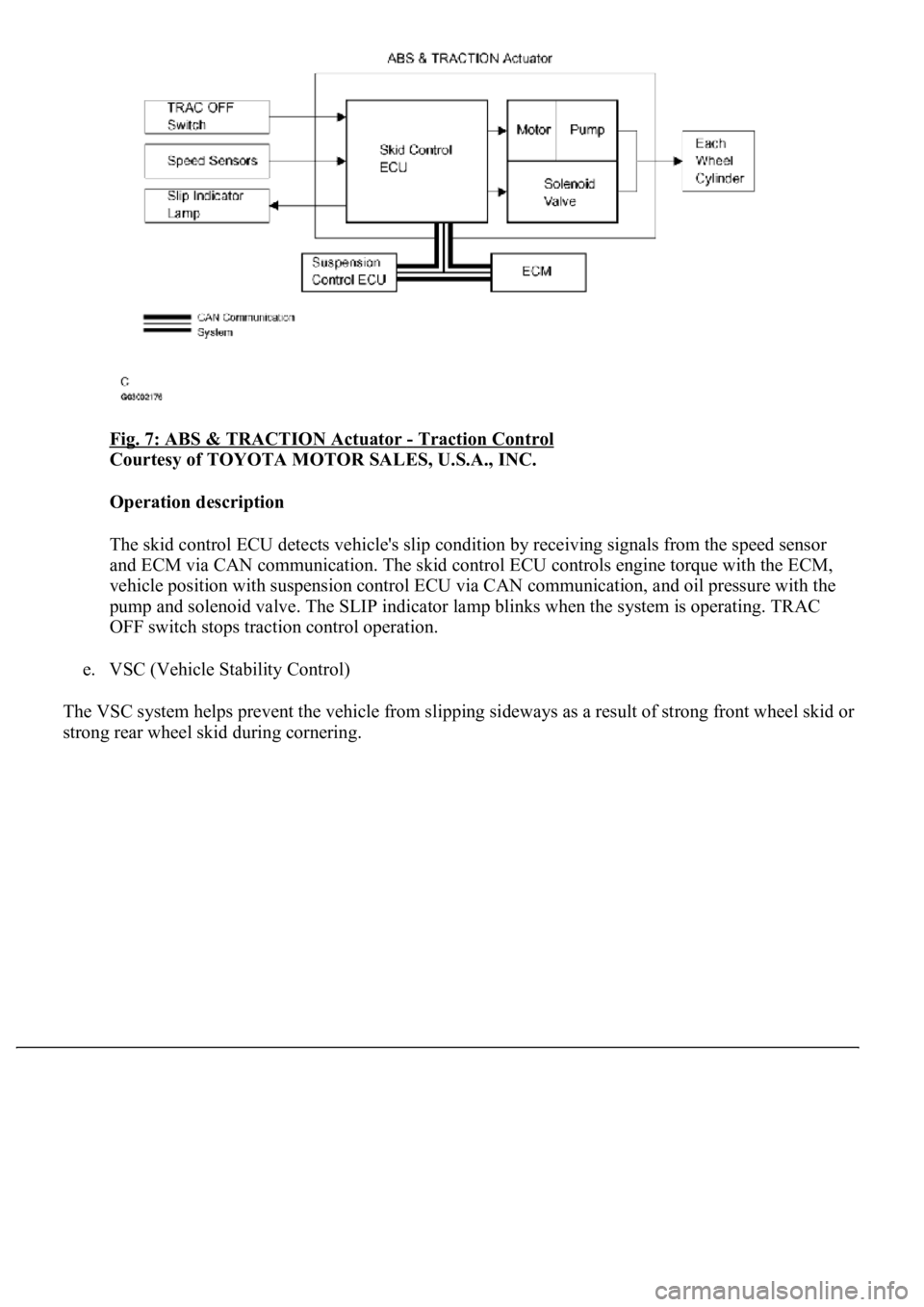
Fig. 7: ABS & TRACTION Actuator - Traction Control
Courtesy of TOYOTA MOTOR SALES, U.S.A., INC.
Operation description
The skid control ECU detects vehicle's slip condition by receiving signals from the speed sensor
<004400510047000300280026003000030059004c004400030026002400310003004600520050005000580051004c004600440057004c00520051001100030037004b004800030056004e004c00470003004600520051005700550052004f00030028002600
380003004600520051005700550052004f0056000300480051[gine torque with the ECM,
vehicle position with suspension control ECU via CAN communication, and oil pressure with the
pump and solenoid valve. The SLIP indicator lamp blinks when the system is operating. TRAC
OFF switch stops traction control operation.
e. VSC (Vehicle Stability Control)
The VSC system helps prevent the vehicle from slipping sideways as a result of strong front wheel skid or
stron
g rear wheel skid during cornering.
Page 12 of 4500
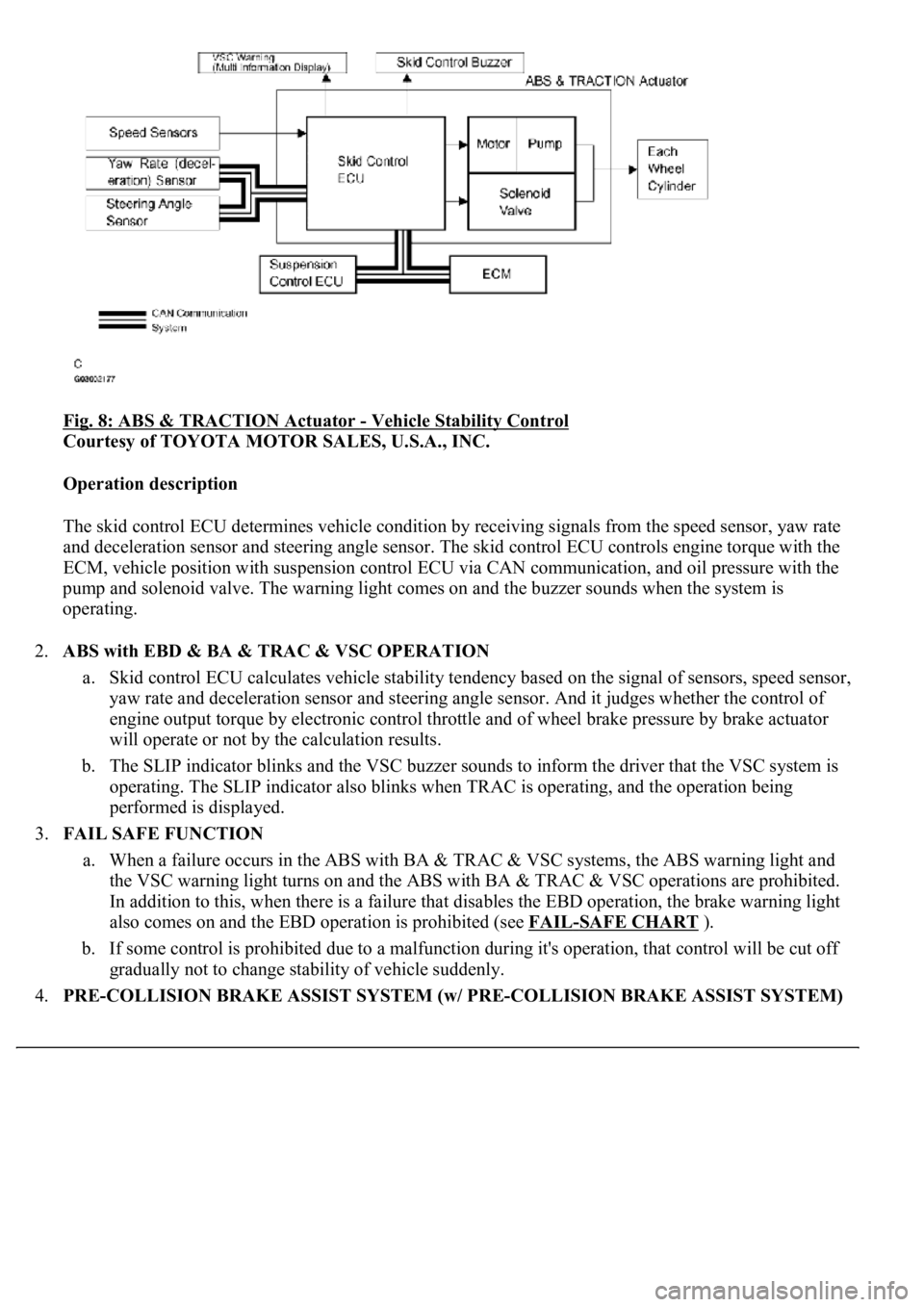
Fig. 8: ABS & TRACTION Actuator - Vehicle Stability Control
Courtesy of TOYOTA MOTOR SALES, U.S.A., INC.
Operation description
The skid control ECU determines vehicle condition by receiving signals from the speed sensor, yaw rate
and deceleration sensor and steering angle sensor. The skid control ECU controls engine torque with the
ECM, vehicle position with suspension control ECU via CAN communication, and oil pressure with the
pump and solenoid valve. The warning light comes on and the buzzer sounds when the system is
operating.
2.ABS with EBD & BA & TRAC & VSC OPERATION
a. Skid control ECU calculates vehicle stability tendency based on the signal of sensors, speed sensor,
yaw rate and deceleration sensor and steering angle sensor. And it judges whether the control of
engine output torque by electronic control throttle and of wheel brake pressure by brake actuator
will operate or not by the calculation results.
b. The SLIP indicator blinks and the VSC buzzer sounds to inform the driver that the VSC system is
operating. The SLIP indicator also blinks when TRAC is operating, and the operation being
performed is displayed.
3.FAIL SAFE FUNCTION
a. When a failure occurs in the ABS with BA & TRAC & VSC systems, the ABS warning light and
the VSC warning light turns on and the ABS with BA & TRAC & VSC operations are prohibited.
In addition to this, when there is a failure that disables the EBD operation, the brake warning light
also comes on and the EBD operation is prohibited (see FAIL
-SAFE CHART ).
b. If some control is prohibited due to a malfunction during it's operation, that control will be cut off
gradually not to change stability of vehicle suddenly.
4.PRE-COLLISION BRAKE ASSIST SYSTEM (w/ PRE-COLLISION BRAKE ASSIST SYSTEM)
Page 20 of 4500
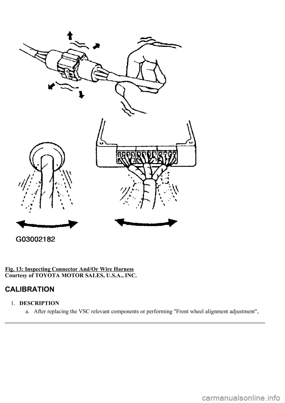
Fig. 13: Inspecting Connector And/Or Wire Harness
Courtesy of TOYOTA MOTOR SALES, U.S.A., INC.
1.DESCRIPTION
a. After replacin
g the VSC relevant components or performing "Front wheel alignment adjustment",
Page 22 of 4500
2. Turn the ignition switch to the ON position.
3. Operate the hand-held tester to erase the codes.
HINT:
Refer to the hand-held tester operator's manual for further details.
Check if "VSC" is displayed on the multi-information display.
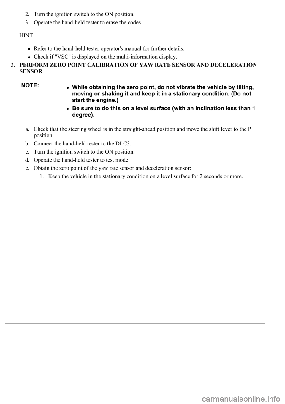
3.PERFORM ZERO POINT CALIBRATION OF YAW RATE SENSOR AND DECELERATION
SENSOR
a. Check that the steering wheel is in the straight-ahead position and move the shift lever to the P
position.
b. Connect the hand-held tester to the DLC3.
c. Turn the ignition switch to the ON position.
d. Operate the hand-held tester to test mode.
e. Obtain the zero point of the yaw rate sensor and deceleration sensor:
1. Keep the vehicle in the stationar
y condition on a level surface for 2 seconds or more.