oil level LEXUS LS430 2003 Factory Repair Manual
[x] Cancel search | Manufacturer: LEXUS, Model Year: 2003, Model line: LS430, Model: LEXUS LS430 2003Pages: 4500, PDF Size: 87.45 MB
Page 819 of 4500
Clean both sealing surfaces with a non-residue solvent.
Parts must be reassembled within 10 minutes of application. Otherwise, the packing (FIPG) material must
be removed and reapplied.
ADJUSTMENT
1.BEFORE TRANSMISSION FILL
This transmission requires Toyota Genuine ATF WS transmission fluid.
After servicing the transmission, you must refill the transmission with the correct amount of fluid.
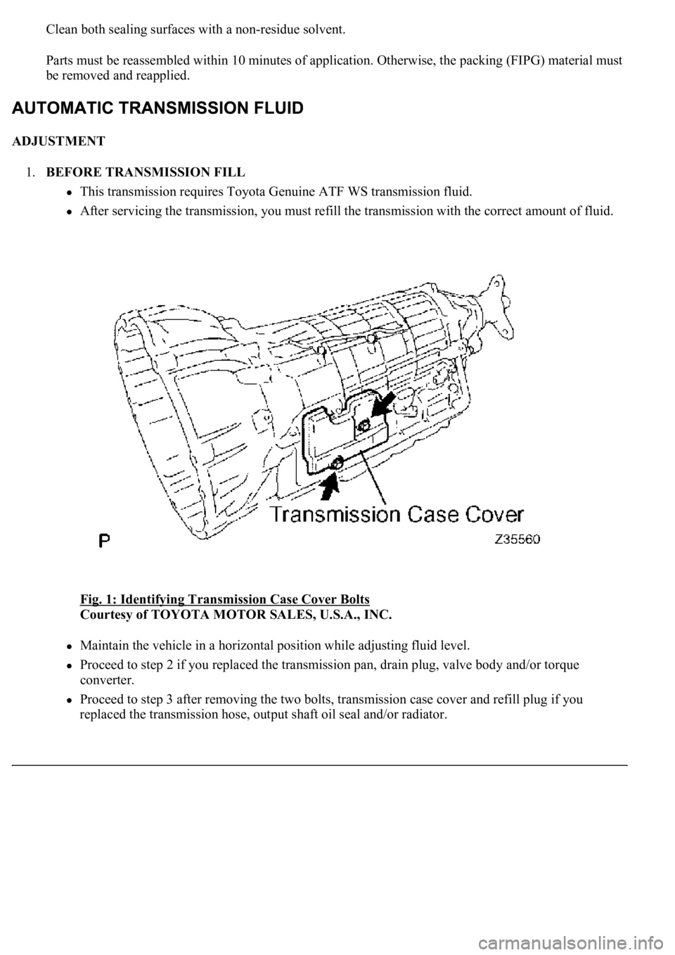
Fig. 1: Identifying Transmission Case Cover Bolts
Courtesy of TOYOTA MOTOR SALES, U.S.A., INC.
Maintain the vehicle in a horizontal position while adjusting fluid level.
Proceed to step 2 if you replaced the transmission pan, drain plug, valve body and/or torque
converter.
Proceed to step 3 after removing the two bolts, transmission case cover and refill plug if you
replaced the transmission hose, output shaft oil seal and/or radiator.
Page 1781 of 4500
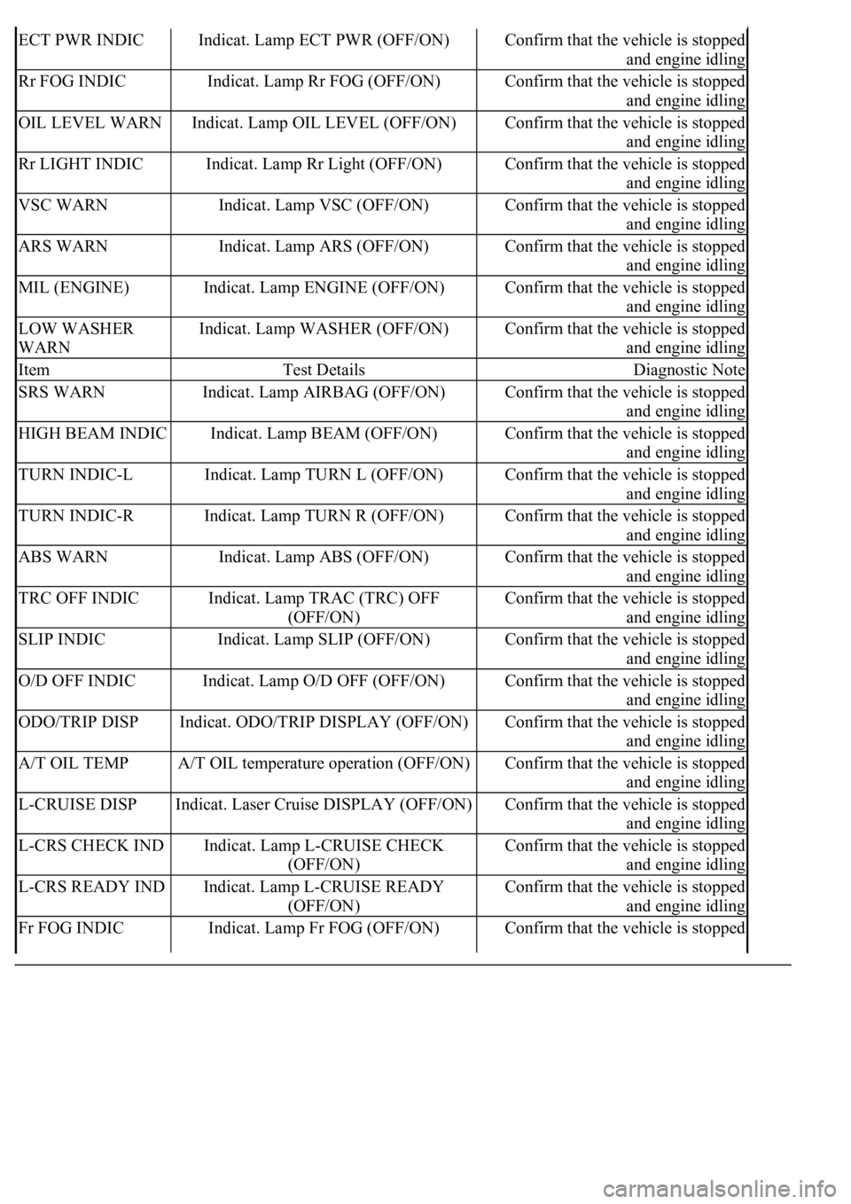
ECT PWR INDICIndicat. Lamp ECT PWR (OFF/ON)Confirm that the vehicle is stopped
and engine idling
Rr FOG INDICIndicat. Lamp Rr FOG (OFF/ON)Confirm that the vehicle is stopped
and engine idling
OIL LEVEL WARNIndicat. Lamp OIL LEVEL (OFF/ON)Confirm that the vehicle is stopped
and engine idling
Rr LIGHT INDICIndicat. Lamp Rr Light (OFF/ON)Confirm that the vehicle is stopped
and engine idling
VSC WARNIndicat. Lamp VSC (OFF/ON)Confirm that the vehicle is stopped
and engine idling
ARS WARNIndicat. Lamp ARS (OFF/ON)Confirm that the vehicle is stopped
and engine idling
MIL (ENGINE)Indicat. Lamp ENGINE (OFF/ON)Confirm that the vehicle is stopped
and engine idling
LOW WASHER
WARNIndicat. Lamp WASHER (OFF/ON)Confirm that the vehicle is stopped
and engine idling
ItemTest DetailsDiagnostic Note
SRS WARNIndicat. Lamp AIRBAG (OFF/ON)Confirm that the vehicle is stopped
and engine idling
HIGH BEAM INDICIndicat. Lamp BEAM (OFF/ON)Confirm that the vehicle is stopped
and engine idling
TURN INDIC-LIndicat. Lamp TURN L (OFF/ON)Confirm that the vehicle is stopped
and engine idling
TURN INDIC-RIndicat. Lamp TURN R (OFF/ON)Confirm that the vehicle is stopped
and engine idling
ABS WARNIndicat. Lamp ABS (OFF/ON)Confirm that the vehicle is stopped
and engine idling
TRC OFF INDICIndicat. Lamp TRAC (TRC) OFF
(OFF/ON)Confirm that the vehicle is stopped
and engine idling
SLIP INDICIndicat. Lamp SLIP (OFF/ON)Confirm that the vehicle is stopped
and engine idling
O/D OFF INDICIndicat. Lamp O/D OFF (OFF/ON)Confirm that the vehicle is stopped
and engine idling
ODO/TRIP DISPIndicat. ODO/TRIP DISPLAY (OFF/ON)Confirm that the vehicle is stopped
and engine idling
A/T OIL TEMPA/T OIL temperature operation (OFF/ON)Confirm that the vehicle is stopped
and engine idling
L-CRUISE DISPIndicat. Laser Cruise DISPLAY (OFF/ON)Confirm that the vehicle is stopped
and engine idling
L-CRS CHECK INDIndicat. Lamp L-CRUISE CHECK
(OFF/ON)Confirm that the vehicle is stopped
and engine idling
L-CRS READY INDIndicat. Lamp L-CRUISE READY
(OFF/ON)Confirm that the vehicle is stopped
and engine idling
Fr FOG INDICIndicat. Lamp Fr FOG (OFF/ON)Confirm that the vehicle is stopped
Page 1847 of 4500
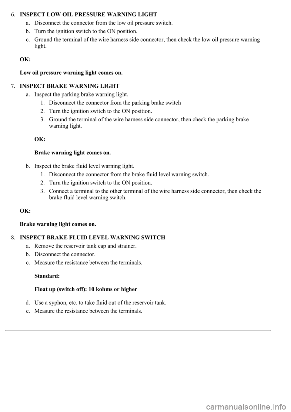
6.INSPECT LOW OIL PRESSURE WARNING LIGHT
a. Disconnect the connector from the low oil pressure switch.
b. Turn the ignition switch to the ON position.
c. Ground the terminal of the wire harness side connector, then check the low oil pressure warning
light.
OK:
Low oil pressure warning light comes on.
7.INSPECT BRAKE WARNING LIGHT
a. Inspect the parking brake warning light.
1. Disconnect the connector from the parking brake switch
2. Turn the ignition switch to the ON position.
3. Ground the terminal of the wire harness side connector, then check the parking brake
warning light.
OK:
Brake warning light comes on.
b. Inspect the brake fluid level warning light.
1. Disconnect the connector from the brake fluid level warning switch.
2. Turn the ignition switch to the ON position.
3. Connect a terminal to the other terminal of the wire harness side connector, then check the
brake fluid level warning switch.
OK:
Brake warning light comes on.
8.INSPECT BRAKE FLUID LEVEL WARNING SWITCH
a. Remove the reservoir tank cap and strainer.
b. Disconnect the connector.
c. Measure the resistance between the terminals.
Standard:
Float up (switch off): 10 kohms or higher
d. Use a syphon, etc. to take fluid out of the reservoir tank.
e. Measure the resistance between the terminals.
Page 1850 of 4500
psi), and check that the pressure does not drop.
If the pressure drops, check the hoses, radiator and water pump for leaks. If no external leaks are found,
check the heater core, cylinder block and head.
2.CHECK ENGINE COOLANT LEVEL AT RESERVOIR
a. Check that the engine coolant level is between the LOW and FULL lines when the engine is cold.
If the engine coolant is low, check for leaks and add "TOYOTA Super Long Life Coolant" to the
FULL line.
If "TOYOTA Super Long Life Coolant" is not available, use a similar high quality ethylene glycol
based non-silicate, non-amino, non-nitrite and non-borate coolant with long-life hybrid organic acid
technology. Do not substitute plain water for engine coolant.
3.CHECK ENGINE COOLANT QUALITY
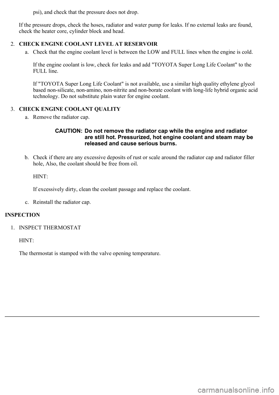
a. Remove the radiator cap.
b. Check if there are any excessive deposits of rust or scale around the radiator cap and radiator filler
hole, Also, the coolant should be free from oil.
HINT:
If excessively dirty, clean the coolant passage and replace the coolant.
c. Reinstall the radiator cap.
INSPECTION
1. INSPECT THERMOSTAT
HINT:
The thermostat is stamped with the valve openin
g temperature.
Page 1968 of 4500
a. Preparation for adjusting the radar beam axis
1. Adjust the tire pressure properly (see INSPECTION
).
2. Luggage in the vehicle, such as in the trunk, should be unloaded.
b. Adjust the standard vehicle height (vehicle with air suspension) (see INSPECTION
)
c. Adjustment in vertical direction of the millimeter wave radar sensor.
1. Remove dust and oil on the level rack of the millimeter wave radar sensor.
2. Set the specified level on the center of the level rack of the millimeter wave radar sensor.
Fig. 21: Setting Specified Level
Courtesy of TOYOTA MOTOR SALES, U.S.A., INC.
3. Using a hexagon wrench, turn and adjust screw A for vertical adjustment of the millimeter
wave radar sensor so that the air bubble is within the red frame on the level.
Standard:
Adjustable range within the red frame of the level is ± 0.2°.
Page 2042 of 4500
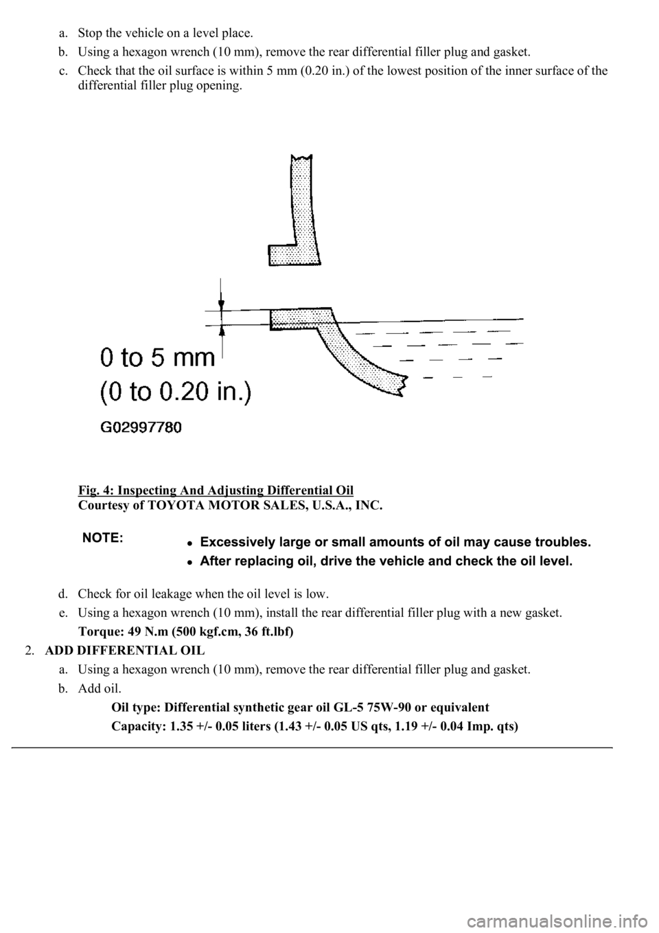
a. Stop the vehicle on a level place.
b. Using a hexagon wrench (10 mm), remove the rear differential filler plug and gasket.
c. Check that the oil surface is within 5 mm (0.20 in.) of the lowest position of the inner surface of the
differential filler plug opening.
Fig. 4: Inspecting And Adjusting Differential Oil
Courtesy of TOYOTA MOTOR SALES, U.S.A., INC.
d. Check for oil leakage when the oil level is low.
e. Using a hexagon wrench (10 mm), install the rear differential filler plug with a new gasket.
Torque: 49 N.m (500 kgf.cm, 36 ft.lbf)
2.ADD DIFFERENTIAL OIL
a. Using a hexagon wrench (10 mm), remove the rear differential filler plug and gasket.
b. Add oil.
Oil type: Differential synthetic gear oil GL-5 75W-90 or equivalent
Capacity: 1.35 +/- 0.05 liters (1.43 +/- 0.05 US qts, 1.19 +/- 0.04 Imp. qts)
Page 2043 of 4500
c. Check the oil level.
d. Using a hexagon wrench (10 mm), install the rear differential filler plug with a new gasket.
Torque: 49 N.m (500 kgf.cm, 36 ft.lbf)
REPLACEMENT
HINT:
See COMPONENTS
Use the same procedures for the RH side and LH side.
1.REMOVE REAR WHEEL
2.REMOVE REAR DIFFERENTIAL FILLER PLUG
a. Using a hexagon wrench (10 mm), remove the filler plug and gasket.
3.REMOVE REAR DIFFERENTIAL DRAIN PLUG
a. Using a hexagon wrench (10 mm), remove the drain plug and gasket.
b. Drain the differential oil.
4.REMOVE REAR DRIVE SHAFT ASSY LH (SEE REPLACEMENT
)
5.REMOVE REAR DIFFERENTIAL SIDE GEAR SHAFT OIL SEAL
a. Using SST, remove the oil seal.
SST 09308-10010
Page 2632 of 4500
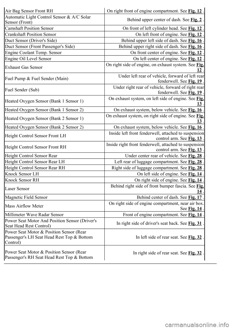
Air Bag Sensor Front RHOn right front of engine compartment. See Fig. 12 .
Automatic Light Control Sensor & A/C Solar
Sensor (Front)Behind upper center of dash. See Fig. 2 .
Camshaft Position SensorOn front of left cylinder head. See Fig. 12 .
Crankshaft Position SensorOn left front of engine. See Fig. 12 .
Duct Sensor (Driver's Side)Behind upper left side of dash. See Fig. 16 .
Duct Sensor (Front Passenger's Side)Behind upper right side of dash. See Fig. 16 .
Engine Coolant Temp. SensorOn front center of engine. See Fig. 12 .
Engine Oil Level SensorOn left center of engine. See Fig. 12 .
Exhaust Gas SensorOn right side of engine, on exhaust system. See Fig.
12 .
Fuel Pump & Fuel Sender (Main)Under left rear of vehicle, forward of left rear
fenderwell. See Fig. 19
.
Fuel Sender (Sub)Under right rear of vehicle, forward of right rear
fenderwell. See Fig. 19
.
Heated Oxygen Sensor (Bank 1 Sensor 1)On exhaust system, on left side of engine. See Fig.
13 .
Heated Oxygen Sensor (Bank 1 Sensor 2)On exhaust system, below vehicle. See Fig. 16 .
Heated Oxygen Sensor (Bank 2 Sensor 1)On exhaust system, on right side of engine. See Fig.
13 .
Heated Oxygen Sensor (Bank 2 Sensor 2)On exhaust system, below vehicle. See Fig. 16 .
Height Control Sensor Front LHInside left front fenderwell, attached to suspension
control arm. See Fig. 13
.
Height Control Sensor Front RHInside right front fenderwell, attached to suspension
control arm. See Fig. 13
.
Height Control Sensor RearUnder center rear of vehicle. See Fig. 28 .
Height Control Sensor Rear LHLeft rear of luggage compartment. See Fig. 28 .
Height Control Sensor Rear RHRight side of luggage compartment. See Fig. 28 .
Knock Sensor LHOn left side of engine. See Fig. 14 .
Knock Sensor RHOn right side of engine. See Fig. 14 .
Laser SensorBehind right side of front bumper fascia. See Fig.
14 .
Magnetic Field SensorBehind center of dash. See Fig. 17 .
Mass Airflow MeterOn right side of engine compartment, near air box.
See Fig. 14
.
Millimeter Wave Radar SensorFront of engine compartment. See Fig. 14 .
Power Seat Motor And Position Sensor (Driver's
Seat Head Rest Control)In right side of driver's seat back. See Fig. 31 .
Power Seat Motor & Position Sensor (Rear
Passenger's LH Seat Head Rest Top & Bottom
Control)
In left side of rear seat. See Fig. 32 .
Power Seat Motor & Position Sensor (Rear
Passenger's RH Seat Head Rest Top & Bottom In right side of rear seat. See Fig. 32 .
Page 2634 of 4500
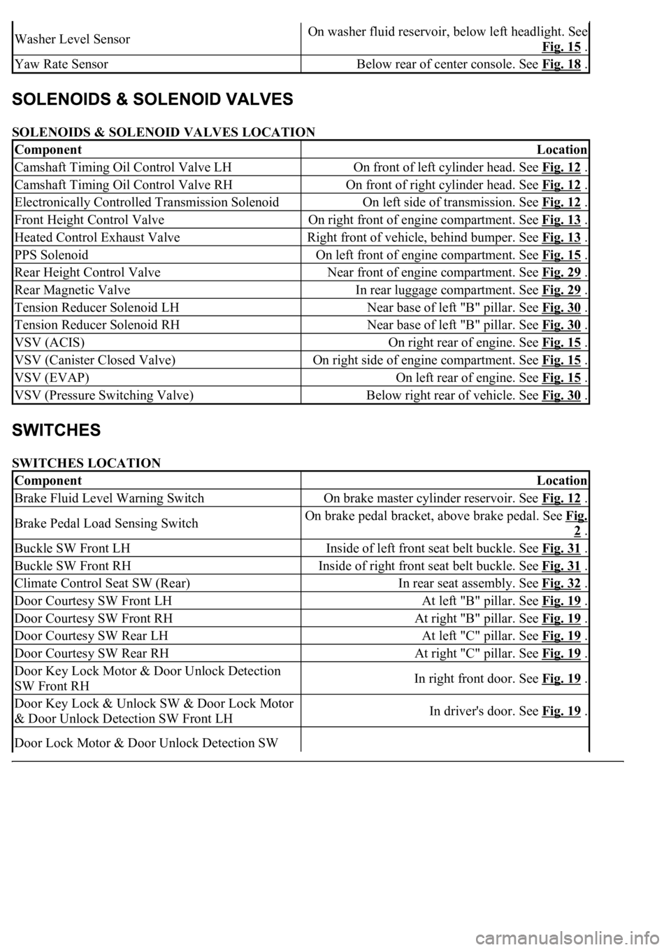
SOLENOIDS & SOLENOID VALVES LOCATION
SWITCHES LOCATION
Washer Level SensorOn washer fluid reservoir, below left headlight. See
Fig. 15
.
Yaw Rate SensorBelow rear of center console. See Fig. 18 .
ComponentLocation
Camshaft Timing Oil Control Valve LHOn front of left cylinder head. See Fig. 12 .
Camshaft Timing Oil Control Valve RHOn front of right cylinder head. See Fig. 12 .
Electronically Controlled Transmission SolenoidOn left side of transmission. See Fig. 12 .
Front Height Control ValveOn right front of engine compartment. See Fig. 13 .
Heated Control Exhaust ValveRight front of vehicle, behind bumper. See Fig. 13 .
PPS SolenoidOn left front of engine compartment. See Fig. 15 .
Rear Height Control ValveNear front of engine compartment. See Fig. 29 .
Rear Magnetic ValveIn rear luggage compartment. See Fig. 29 .
Tension Reducer Solenoid LHNear base of left "B" pillar. See Fig. 30 .
Tension Reducer Solenoid RHNear base of left "B" pillar. See Fig. 30 .
VSV (ACIS)On right rear of engine. See Fig. 15 .
VSV (Canister Closed Valve)On right side of engine compartment. See Fig. 15 .
VSV (EVAP)On left rear of engine. See Fig. 15 .
VSV (Pressure Switching Valve)Below right rear of vehicle. See Fig. 30 .
ComponentLocation
Brake Fluid Level Warning SwitchOn brake master cylinder reservoir. See Fig. 12 .
Brake Pedal Load Sensing SwitchOn brake pedal bracket, above brake pedal. See Fig.
2 .
Buckle SW Front LHInside of left front seat belt buckle. See Fig. 31 .
Buckle SW Front RHInside of right front seat belt buckle. See Fig. 31 .
Climate Control Seat SW (Rear)In rear seat assembly. See Fig. 32 .
Door Courtesy SW Front LHAt left "B" pillar. See Fig. 19 .
Door Courtesy SW Front RHAt right "B" pillar. See Fig. 19 .
Door Courtesy SW Rear LHAt left "C" pillar. See Fig. 19 .
Door Courtesy SW Rear RHAt right "C" pillar. See Fig. 19 .
Door Key Lock Motor & Door Unlock Detection
SW Front RHIn right front door. See Fig. 19 .
Door Key Lock & Unlock SW & Door Lock Motor
& Door Unlock Detection SW Front LHIn driver's door. See Fig. 19 .
Door Lock Motor & Door Unlock Detection SW
Page 3283 of 4500
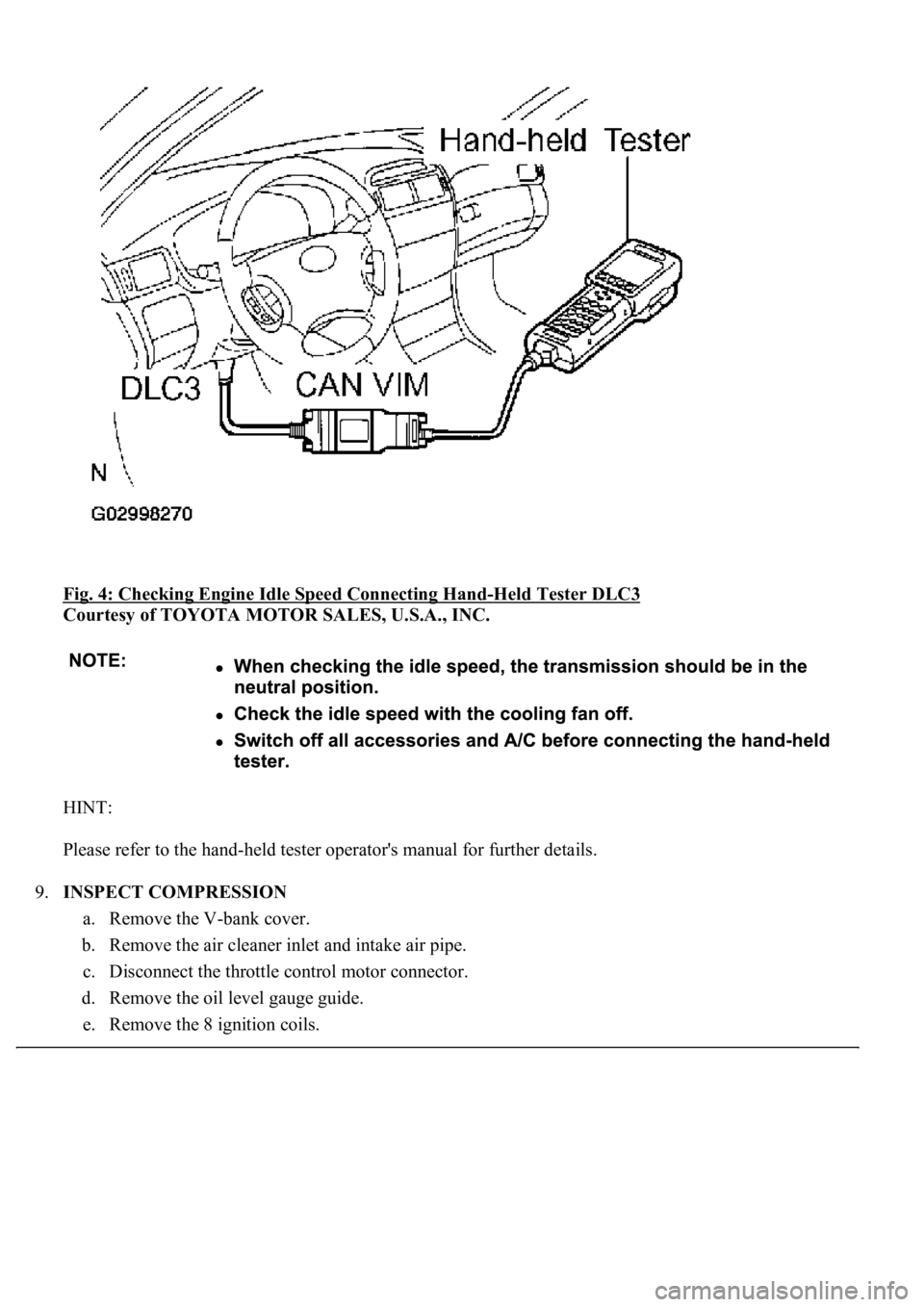
Fig. 4: Checking Engine Idle Speed Connecting Hand-Held Tester DLC3
Courtesy of TOYOTA MOTOR SALES, U.S.A., INC.
HINT:
Please refer to the hand-held tester operator's manual for further details.
9.INSPECT COMPRESSION
a. Remove the V-bank cover.
b. Remove the air cleaner inlet and intake air pipe.
c. Disconnect the throttle control motor connector.
d. Remove the oil level gauge guide.
e. Remove the 8 i
gnition coils.