oil temperature LEXUS LS430 2003 Factory Repair Manual
[x] Cancel search | Manufacturer: LEXUS, Model Year: 2003, Model line: LS430, Model: LEXUS LS430 2003Pages: 4500, PDF Size: 87.45 MB
Page 822 of 4500
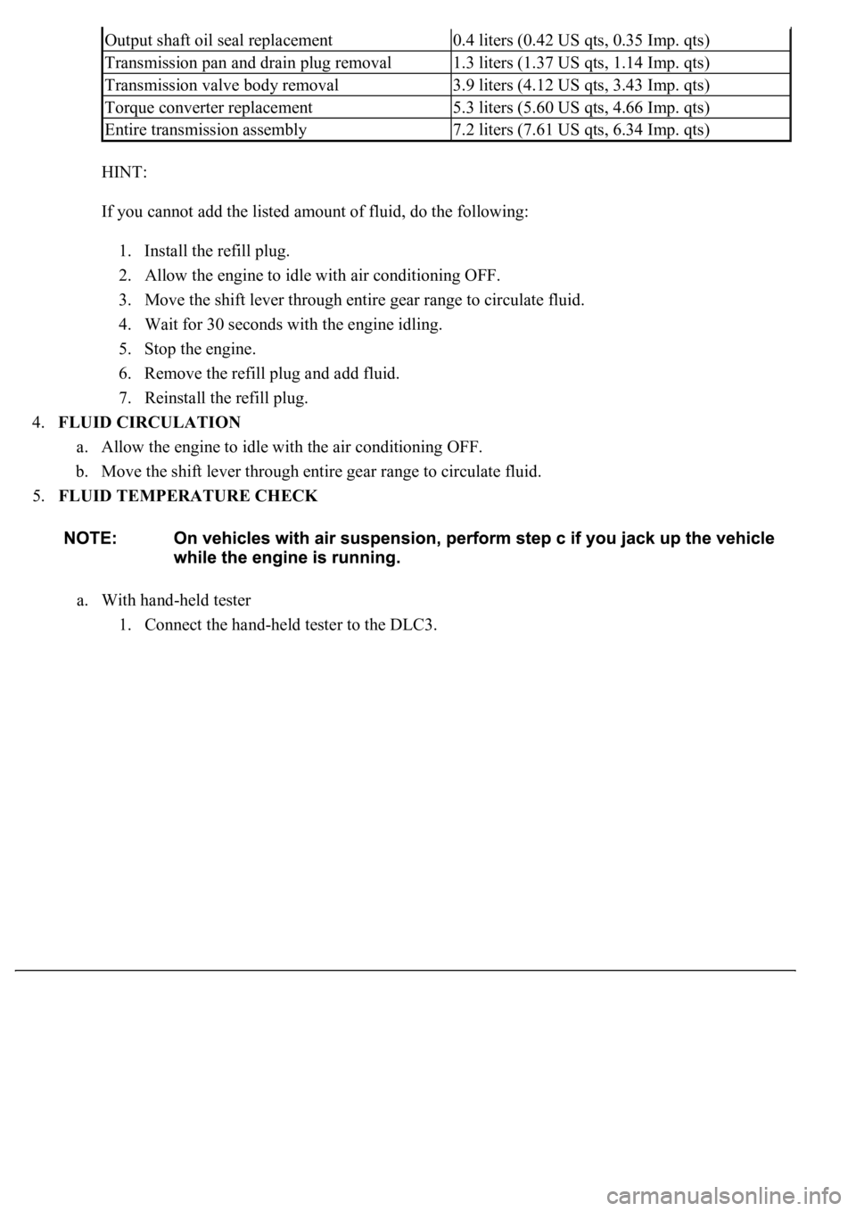
HINT:
If you cannot add the listed amount of fluid, do the following:
1. Install the refill plug.
2. Allow the engine to idle with air conditioning OFF.
3. Move the shift lever through entire gear range to circulate fluid.
4. Wait for 30 seconds with the engine idling.
5. Stop the engine.
6. Remove the refill plug and add fluid.
7. Reinstall the refill plug.
4.FLUID CIRCULATION
a. Allow the engine to idle with the air conditioning OFF.
b. Move the shift lever through entire gear range to circulate fluid.
5.FLUID TEMPERATURE CHECK
a. With hand-held tester
1. Connect the han
d-held tester to the DLC3.
Output shaft oil seal replacement0.4 liters (0.42 US qts, 0.35 Imp. qts)
Transmission pan and drain plug removal1.3 liters (1.37 US qts, 1.14 Imp. qts)
Transmission valve body removal3.9 liters (4.12 US qts, 3.43 Imp. qts)
Torque converter replacement5.3 liters (5.60 US qts, 4.66 Imp. qts)
Entire transmission assembly7.2 liters (7.61 US qts, 6.34 Imp. qts)
Page 823 of 4500
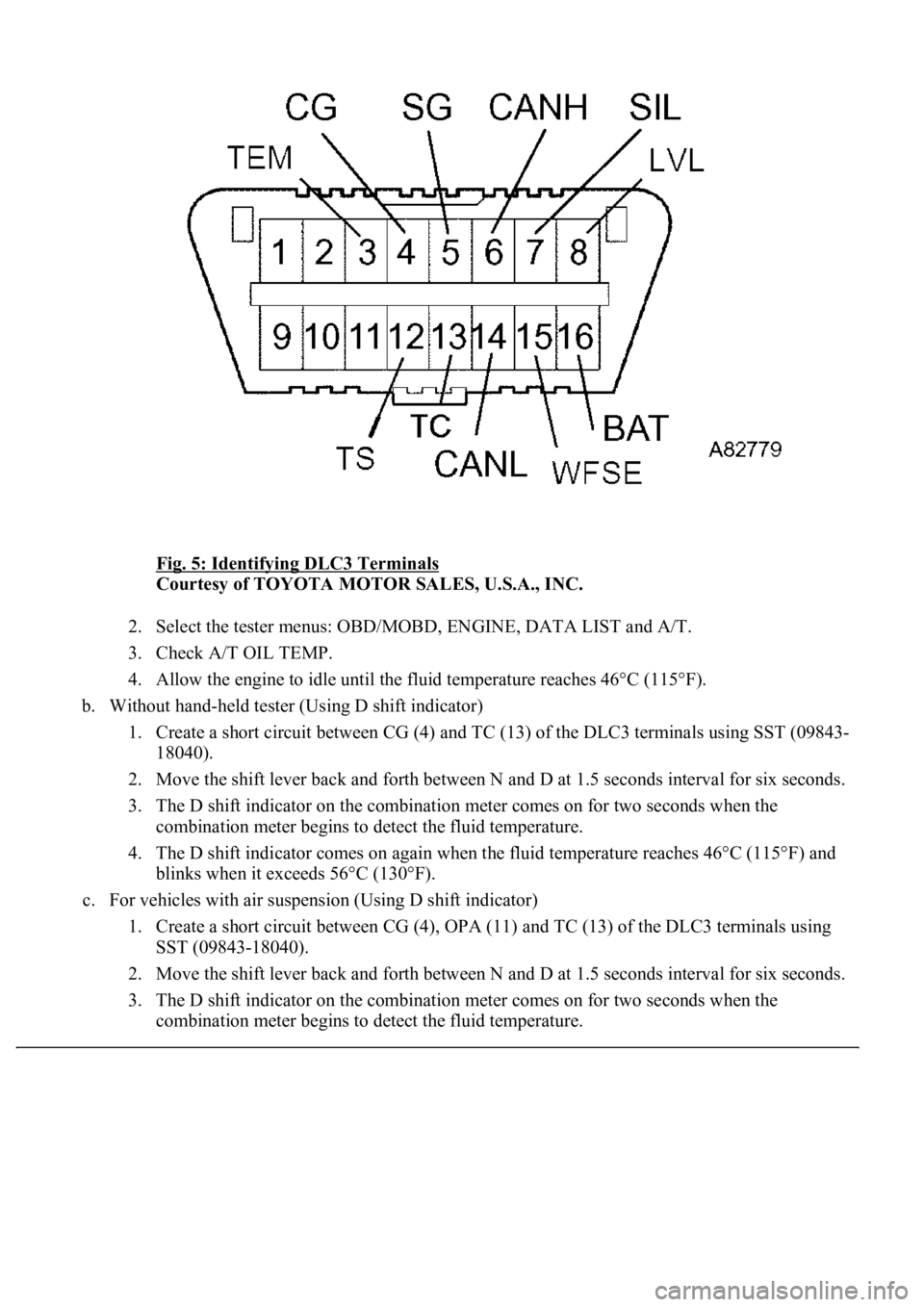
Fig. 5: Identifying DLC3 Terminals
Courtesy of TOYOTA MOTOR SALES, U.S.A., INC.
2. Select the tester menus: OBD/MOBD, ENGINE, DATA LIST and A/T.
3. Check A/T OIL TEMP.
4. Allow the engine to idle until the fluid temperature reaches 46°C (115°F).
b. Without hand-held tester (Using D shift indicator)
1. Create a short circuit between CG (4) and TC (13) of the DLC3 terminals using SST (09843-
18040).
2. Move the shift lever back and forth between N and D at 1.5 seconds interval for six seconds.
3. The D shift indicator on the combination meter comes on for two seconds when the
combination meter begins to detect the fluid temperature.
4. The D shift indicator comes on again when the fluid temperature reaches 46°C (115°F) and
blinks when it exceeds 56°C (130°F).
c. For vehicles with air suspension (Using D shift indicator)
1. Create a short circuit between CG (4), OPA (11) and TC (13) of the DLC3 terminals using
SST (09843-18040).
2. Move the shift lever back and forth between N and D at 1.5 seconds interval for six seconds.
3. The D shift indicator on the combination meter comes on for two seconds when the
combination meter begins to detect the fluid temperature.
Page 885 of 4500
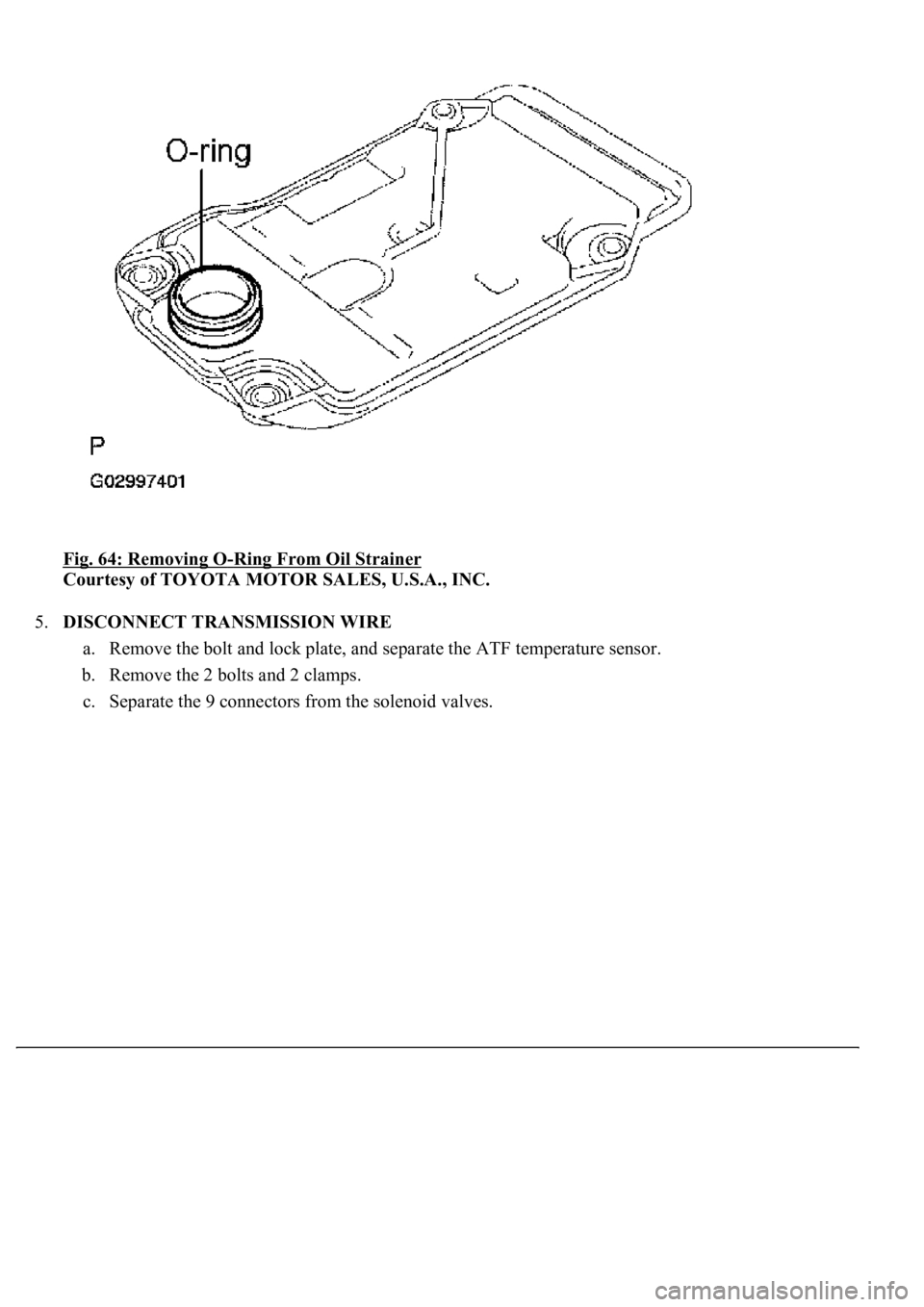
Fig. 64: Removing O-Ring From Oil Strainer
Courtesy of TOYOTA MOTOR SALES, U.S.A., INC.
5.DISCONNECT TRANSMISSION WIRE
a. Remove the bolt and lock plate, and separate the ATF temperature sensor.
b. Remove the 2 bolts and 2 clamps.
c. Separate the 9 connectors from the solenoid valves.
Page 889 of 4500

Fig. 68: Installing ATF Temperature Sensor And Lock Plate With Bolt
Courtesy of TOYOTA MOTOR SALES, U.S.A., INC.
9.INSTALL VALVE BODY OIL STRAINER ASSY
a. Coat a new O-ring with ATF.
b. Install the O-ring.
Page 898 of 4500

Fig. 77: Removing O-Ring From Oil Strainer
Courtesy of TOYOTA MOTOR SALES, U.S.A., INC.
5.DISCONNECT TRANSMISSION WIRE
a. Remove the bolt and lock plate, and separate the ATF temperature sensor.
b. Remove the 2 bolts and 2 clamps.
c. Separate the 9 connectors from the solenoid valves.
Page 908 of 4500

Fig. 86: Installing ATF Temperature Sensor And Lock Plate With Bolt
Courtesy of TOYOTA MOTOR SALES, U.S.A., INC.
9.INSTALL VALVE BODY OIL STRAINER ASSY
a. Coat a new O-ring with ATF.
b. Install the O-ring.
Page 1781 of 4500
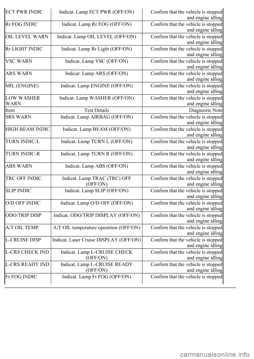
ECT PWR INDICIndicat. Lamp ECT PWR (OFF/ON)Confirm that the vehicle is stopped
and engine idling
Rr FOG INDICIndicat. Lamp Rr FOG (OFF/ON)Confirm that the vehicle is stopped
and engine idling
OIL LEVEL WARNIndicat. Lamp OIL LEVEL (OFF/ON)Confirm that the vehicle is stopped
and engine idling
Rr LIGHT INDICIndicat. Lamp Rr Light (OFF/ON)Confirm that the vehicle is stopped
and engine idling
VSC WARNIndicat. Lamp VSC (OFF/ON)Confirm that the vehicle is stopped
and engine idling
ARS WARNIndicat. Lamp ARS (OFF/ON)Confirm that the vehicle is stopped
and engine idling
MIL (ENGINE)Indicat. Lamp ENGINE (OFF/ON)Confirm that the vehicle is stopped
and engine idling
LOW WASHER
WARNIndicat. Lamp WASHER (OFF/ON)Confirm that the vehicle is stopped
and engine idling
ItemTest DetailsDiagnostic Note
SRS WARNIndicat. Lamp AIRBAG (OFF/ON)Confirm that the vehicle is stopped
and engine idling
HIGH BEAM INDICIndicat. Lamp BEAM (OFF/ON)Confirm that the vehicle is stopped
and engine idling
TURN INDIC-LIndicat. Lamp TURN L (OFF/ON)Confirm that the vehicle is stopped
and engine idling
TURN INDIC-RIndicat. Lamp TURN R (OFF/ON)Confirm that the vehicle is stopped
and engine idling
ABS WARNIndicat. Lamp ABS (OFF/ON)Confirm that the vehicle is stopped
and engine idling
TRC OFF INDICIndicat. Lamp TRAC (TRC) OFF
(OFF/ON)Confirm that the vehicle is stopped
and engine idling
SLIP INDICIndicat. Lamp SLIP (OFF/ON)Confirm that the vehicle is stopped
and engine idling
O/D OFF INDICIndicat. Lamp O/D OFF (OFF/ON)Confirm that the vehicle is stopped
and engine idling
ODO/TRIP DISPIndicat. ODO/TRIP DISPLAY (OFF/ON)Confirm that the vehicle is stopped
and engine idling
A/T OIL TEMPA/T OIL temperature operation (OFF/ON)Confirm that the vehicle is stopped
and engine idling
L-CRUISE DISPIndicat. Laser Cruise DISPLAY (OFF/ON)Confirm that the vehicle is stopped
and engine idling
L-CRS CHECK INDIndicat. Lamp L-CRUISE CHECK
(OFF/ON)Confirm that the vehicle is stopped
and engine idling
L-CRS READY INDIndicat. Lamp L-CRUISE READY
(OFF/ON)Confirm that the vehicle is stopped
and engine idling
Fr FOG INDICIndicat. Lamp Fr FOG (OFF/ON)Confirm that the vehicle is stopped
Page 1850 of 4500
psi), and check that the pressure does not drop.
If the pressure drops, check the hoses, radiator and water pump for leaks. If no external leaks are found,
check the heater core, cylinder block and head.
2.CHECK ENGINE COOLANT LEVEL AT RESERVOIR
a. Check that the engine coolant level is between the LOW and FULL lines when the engine is cold.
If the engine coolant is low, check for leaks and add "TOYOTA Super Long Life Coolant" to the
FULL line.
If "TOYOTA Super Long Life Coolant" is not available, use a similar high quality ethylene glycol
based non-silicate, non-amino, non-nitrite and non-borate coolant with long-life hybrid organic acid
technology. Do not substitute plain water for engine coolant.
3.CHECK ENGINE COOLANT QUALITY
a. Remove the radiator cap.
b. Check if there are any excessive deposits of rust or scale around the radiator cap and radiator filler
hole, Also, the coolant should be free from oil.
HINT:
If excessively dirty, clean the coolant passage and replace the coolant.
c. Reinstall the radiator cap.
INSPECTION
1. INSPECT THERMOSTAT
HINT:
The thermostat is stamped with the valve openin
g temperature.
Page 2669 of 4500
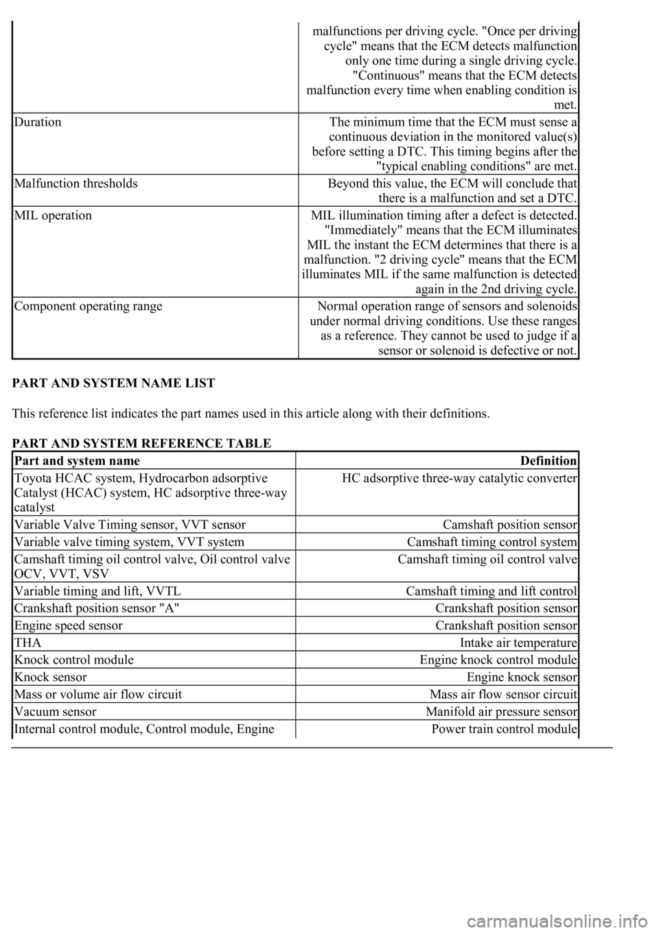
PART AND SYSTEM NAME LIST
This reference list indicates the part names used in this article along with their definitions.
PART AND SYSTEM REFERENCE TABLE
malfunctions per driving cycle. "Once per driving
cycle" means that the ECM detects malfunction
only one time during a single driving cycle.
"Continuous" means that the ECM detects
malfunction every time when enabling condition is
met.
DurationThe minimum time that the ECM must sense a
continuous deviation in the monitored value(s)
before setting a DTC. This timing begins after the
"typical enabling conditions" are met.
Malfunction thresholdsBeyond this value, the ECM will conclude that
there is a malfunction and set a DTC.
MIL operationMIL illumination timing after a defect is detected.
"Immediately" means that the ECM illuminates
MIL the instant the ECM determines that there is a
malfunction. "2 driving cycle" means that the ECM
illuminates MIL if the same malfunction is detected
again in the 2nd driving cycle.
Component operating rangeNormal operation range of sensors and solenoids
under normal driving conditions. Use these ranges
as a reference. They cannot be used to judge if a
sensor or solenoid is defective or not.
Part and system nameDefinition
Toyota HCAC system, Hydrocarbon adsorptive
Catalyst (HCAC) system, HC adsorptive three-way
catalystHC adsorptive three-way catalytic converter
Variable Valve Timing sensor, VVT sensorCamshaft position sensor
Variable valve timing system, VVT systemCamshaft timing control system
Camshaft timing oil control valve, Oil control valve
OCV, VVT, VSVCamshaft timing oil control valve
Variable timing and lift, VVTLCamshaft timing and lift control
Crankshaft position sensor "A"Crankshaft position sensor
Engine speed sensorCrankshaft position sensor
THAIntake air temperature
Knock control moduleEngine knock control module
Knock sensorEngine knock sensor
Mass or volume air flow circuitMass air flow sensor circuit
Vacuum sensorManifold air pressure sensor
Internal control module, Control module, Engine Power train control module
Page 2740 of 4500
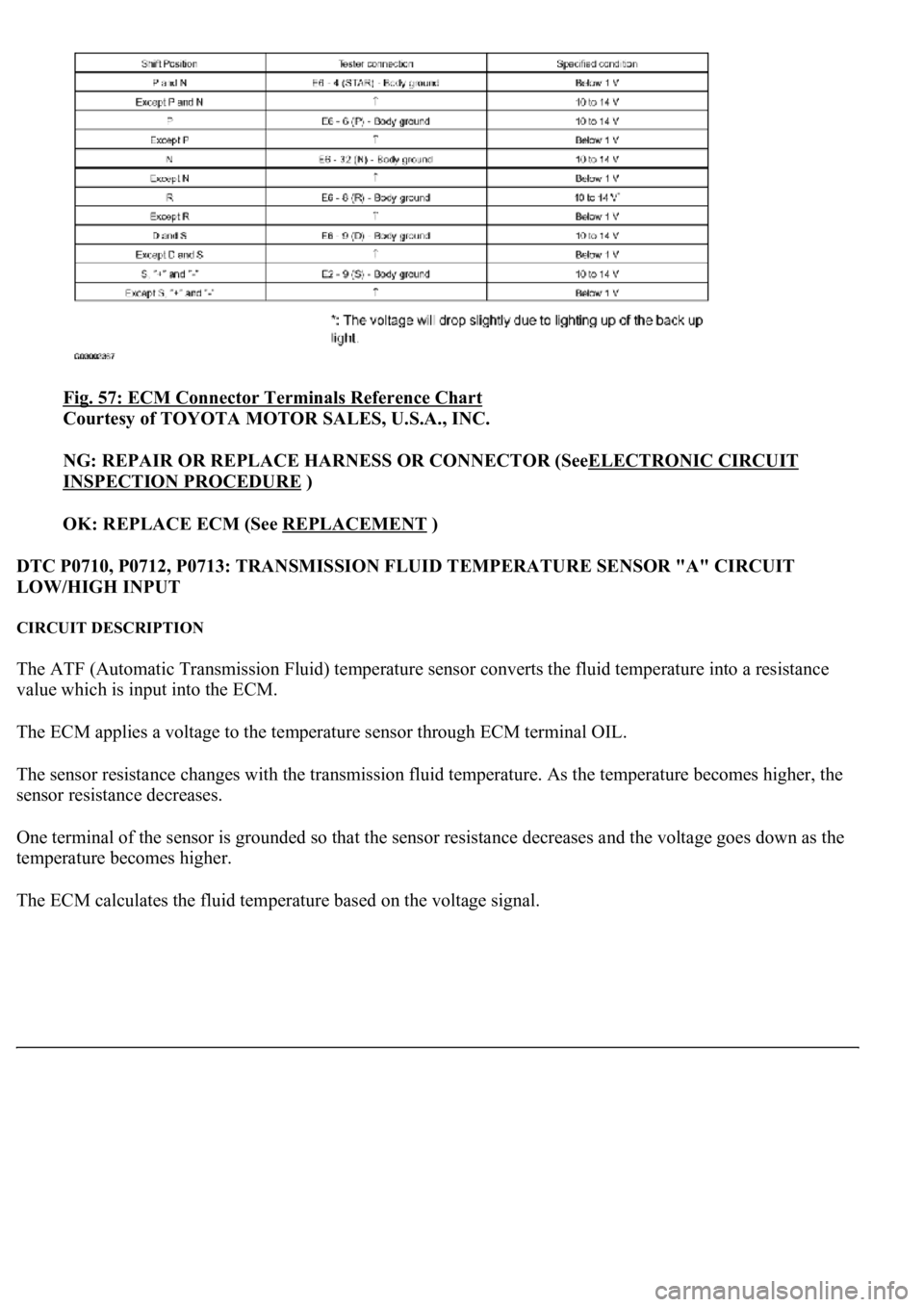
Fig. 57: ECM Connector Terminals Reference Chart
Courtesy of TOYOTA MOTOR SALES, U.S.A., INC.
NG: REPAIR OR REPLACE HARNESS OR CONNECTOR (SeeELECTRONIC CIRCUIT
INSPECTION PROCEDURE )
OK: REPLACE ECM (See REPLACEMENT
)
DTC P0710, P0712, P0713: TRANSMISSION FLUID TEMPERATURE SENSOR "A" CIRCUIT
LOW/HIGH INPUT
CIRCUIT DESCRIPTION
The ATF (Automatic Transmission Fluid) temperature sensor converts the fluid temperature into a resistance
value which is input into the ECM.
The ECM applies a voltage to the temperature sensor through ECM terminal OIL.
The sensor resistance changes with the transmission fluid temperature. As the temperature becomes higher, the
sensor resistance decreases.
One terminal of the sensor is grounded so that the sensor resistance decreases and the voltage goes down as the
temperature becomes higher.
The ECM calculates the fluid temperature based on the volta
ge signal.