relay LEXUS LS430 2003 Factory Repair Manual
[x] Cancel search | Manufacturer: LEXUS, Model Year: 2003, Model line: LS430, Model: LEXUS LS430 2003Pages: 4500, PDF Size: 87.45 MB
Page 39 of 4500
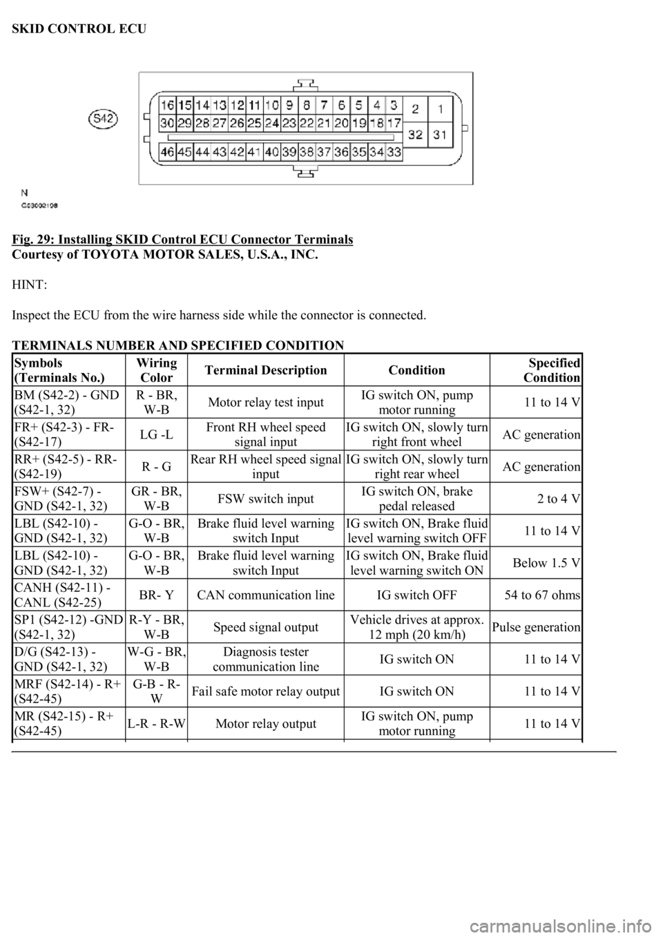
SKID CONTROL ECU
Fig. 29: Installing SKID Control ECU Connector Terminals
Courtesy of TOYOTA MOTOR SALES, U.S.A., INC.
HINT:
Inspect the ECU from the wire harness side while the connector is connected.
TERMINALS NUMBER AND SPECIFIED CONDITION
Symbols
(Terminals No.)Wiring
ColorTerminal DescriptionConditionSpecified
Condition
BM (S42-2) - GND
(S42-1, 32)R - BR,
W-BMotor relay test inputIG switch ON, pump
motor running11 to 14 V
FR+ (S42-3) - FR-
(S42-17)LG -LFront RH wheel speed
signal inputIG switch ON, slowly turn
right front wheelAC generation
RR+ (S42-5) - RR-
(S42-19)R - GRear RH wheel speed signal
inputIG switch ON, slowly turn
right rear wheelAC generation
FSW+ (S42-7) -
GND (S42-1, 32)GR - BR,
W-BFSW switch inputIG switch ON, brake
pedal released2 to 4 V
LBL (S42-10) -
GND (S42-1, 32)G-O - BR,
W-BBrake fluid level warning
switch InputIG switch ON, Brake fluid
level warning switch OFF11 to 14 V
LBL (S42-10) -
GND (S42-1, 32)G-O - BR,
W-BBrake fluid level warning
switch InputIG switch ON, Brake fluid
level warning switch ONBelow 1.5 V
CANH (S42-11) -
CANL (S42-25)BR- YCAN communication lineIG switch OFF54 to 67 ohms
SP1 (S42-12) -GND
(S42-1, 32)R-Y - BR,
W-BSpeed signal outputVehicle drives at approx.
12 mph (20 km/h)Pulse generation
D/G (S42-13) -
GND (S42-1, 32)W-G - BR,
W-BDiagnosis tester
communication lineIG switch ON11 to 14 V
MRF (S42-14) - R+
(S42-45)G-B - R-
WFail safe motor relay outputIG switch ON11 to 14 V
MR (S42-15) - R+
(S42-45)L-R - R-WMotor relay outputIG switch ON, pump
motor running11 to 14 V
Page 40 of 4500
1.DIAGNOSIS
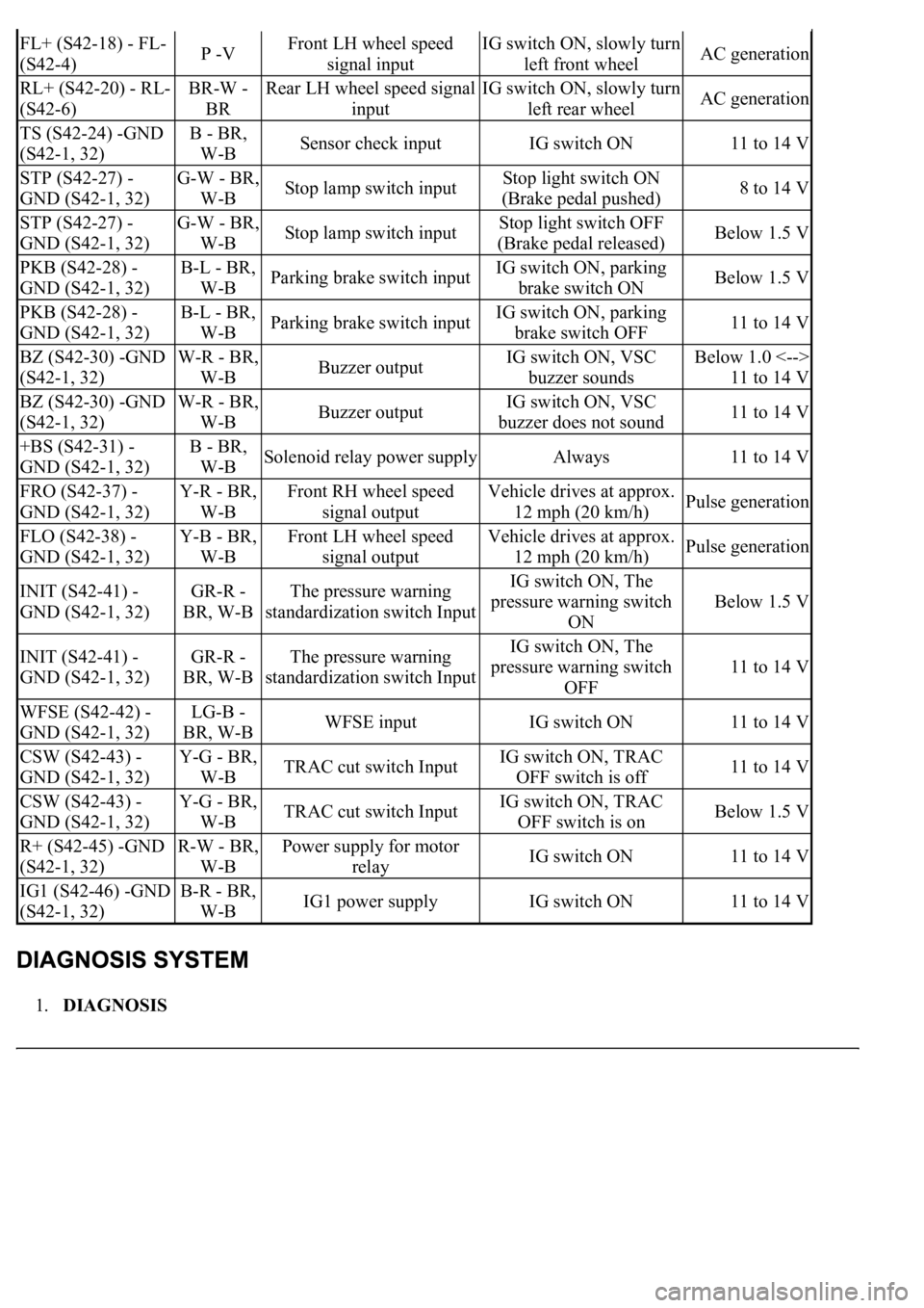
FL+ (S42-18) - FL-
(S42-4)P -VFront LH wheel speed
signal inputIG switch ON, slowly turn
left front wheelAC generation
RL+ (S42-20) - RL-
(S42-6)BR-W -
BRRear LH wheel speed signal
inputIG switch ON, slowly turn
left rear wheelAC generation
TS (S42-24) -GND
(S42-1, 32)B - BR,
W-BSensor check inputIG switch ON11 to 14 V
STP (S42-27) -
GND (S42-1, 32)G-W - BR,
W-BStop lamp switch inputStop light switch ON
(Brake pedal pushed)8 to 14 V
STP (S42-27) -
GND (S42-1, 32)G-W - BR,
W-BStop lamp switch inputStop light switch OFF
(Brake pedal released)Below 1.5 V
PKB (S42-28) -
GND (S42-1, 32)B-L - BR,
W-BParking brake switch inputIG switch ON, parking
brake switch ONBelow 1.5 V
PKB (S42-28) -
GND (S42-1, 32)B-L - BR,
W-BParking brake switch inputIG switch ON, parking
brake switch OFF11 to 14 V
BZ (S42-30) -GND
(S42-1, 32)W-R - BR,
W-BBuzzer outputIG switch ON, VSC
buzzer soundsBelow 1.0 <-->
11 to 14 V
BZ (S42-30) -GND
(S42-1, 32)W-R - BR,
W-BBuzzer outputIG switch ON, VSC
buzzer does not sound11 to 14 V
+BS (S42-31) -
GND (S42-1, 32)B - BR,
W-BSolenoid relay power supplyAlways11 to 14 V
FRO (S42-37) -
GND (S42-1, 32)Y-R - BR,
W-BFront RH wheel speed
signal outputVehicle drives at approx.
12 mph (20 km/h)Pulse generation
FLO (S42-38) -
GND (S42-1, 32)Y-B - BR,
W-BFront LH wheel speed
signal outputVehicle drives at approx.
12 mph (20 km/h)Pulse generation
INIT (S42-41) -
GND (S42-1, 32)GR-R -
BR, W-BThe pressure warning
standardization switch InputIG switch ON, The
pressure warning switch
ON
Below 1.5 V
INIT (S42-41) -
GND (S42-1, 32)GR-R -
BR, W-BThe pressure warning
standardization switch InputIG switch ON, The
pressure warning switch
OFF
11 to 14 V
WFSE (S42-42) -
GND (S42-1, 32)LG-B -
BR, W-BWFSE inputIG switch ON11 to 14 V
CSW (S42-43) -
GND (S42-1, 32)Y-G - BR,
W-BTRAC cut switch InputIG switch ON, TRAC
OFF switch is off11 to 14 V
CSW (S42-43) -
GND (S42-1, 32)Y-G - BR,
W-BTRAC cut switch InputIG switch ON, TRAC
OFF switch is onBelow 1.5 V
R+ (S42-45) -GND
(S42-1, 32)R-W - BR,
W-BPower supply for motor
relayIG switch ON11 to 14 V
IG1 (S42-46) -GND
(S42-1, 32)B-R - BR,
W-BIG1 power supplyIG switch ON11 to 14 V
Page 54 of 4500
HINT:
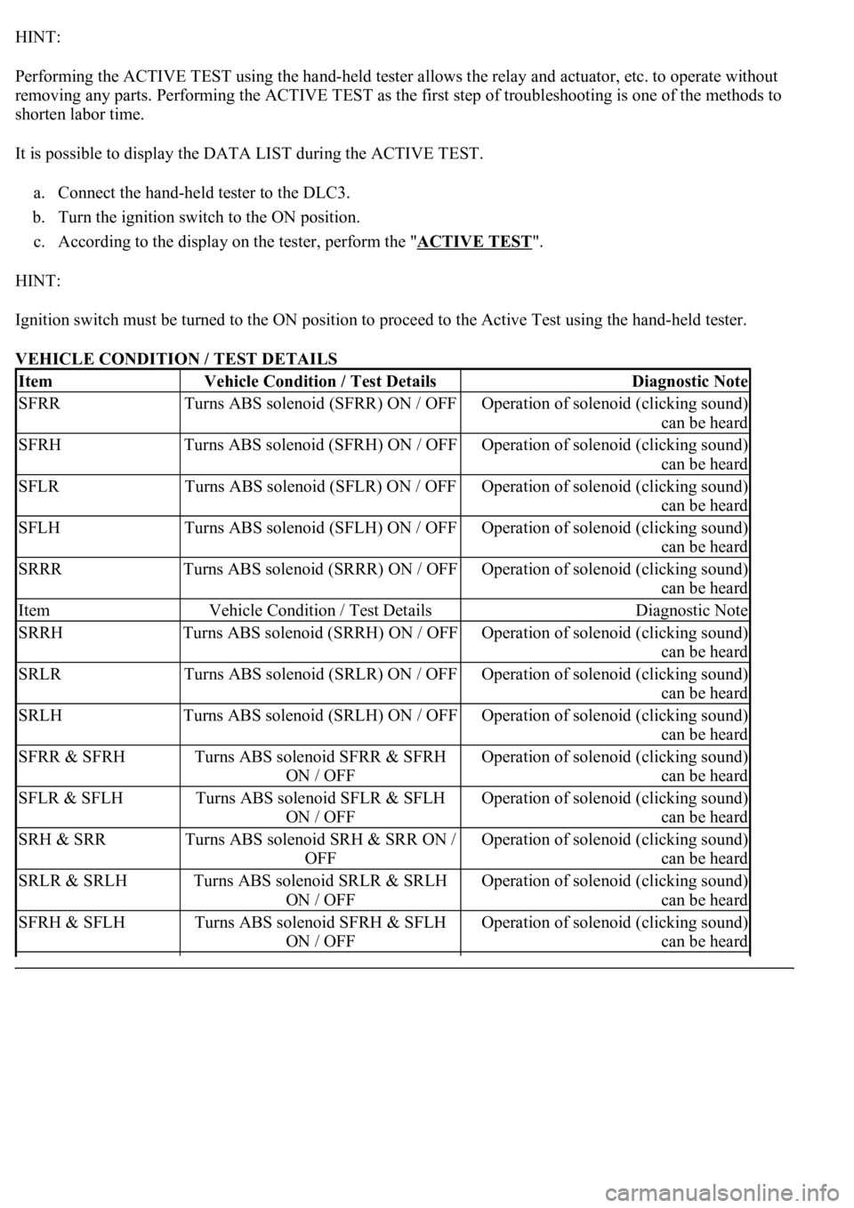
Performing the ACTIVE TEST using the hand-held tester allows the relay and actuator, etc. to operate without
removing any parts. Performing the ACTIVE TEST as the first step of troubleshooting is one of the methods to
shorten labor time.
It is possible to display the DATA LIST during the ACTIVE TEST.
a. Connect the hand-held tester to the DLC3.
b. Turn the ignition switch to the ON position.
c. According to the display on the tester, perform the "ACTIVE TEST
".
HINT:
Ignition switch must be turned to the ON position to proceed to the Active Test using the hand-held tester.
VEHICLE CONDITION / TEST DETAILS
ItemVehicle Condition / Test DetailsDiagnostic Note
SFRRTurns ABS solenoid (SFRR) ON / OFFOperation of solenoid (clicking sound)
can be heard
SFRHTurns ABS solenoid (SFRH) ON / OFFOperation of solenoid (clicking sound)
can be heard
SFLRTurns ABS solenoid (SFLR) ON / OFFOperation of solenoid (clicking sound)
can be heard
SFLHTurns ABS solenoid (SFLH) ON / OFFOperation of solenoid (clicking sound)
can be heard
SRRRTurns ABS solenoid (SRRR) ON / OFFOperation of solenoid (clicking sound)
can be heard
ItemVehicle Condition / Test DetailsDiagnostic Note
SRRHTurns ABS solenoid (SRRH) ON / OFFOperation of solenoid (clicking sound)
can be heard
SRLRTurns ABS solenoid (SRLR) ON / OFFOperation of solenoid (clicking sound)
can be heard
SRLHTurns ABS solenoid (SRLH) ON / OFFOperation of solenoid (clicking sound)
can be heard
SFRR & SFRHTurns ABS solenoid SFRR & SFRH
ON / OFFOperation of solenoid (clicking sound)
can be heard
SFLR & SFLHTurns ABS solenoid SFLR & SFLH
ON / OFFOperation of solenoid (clicking sound)
can be heard
SRH & SRRTurns ABS solenoid SRH & SRR ON /
OFFOperation of solenoid (clicking sound)
can be heard
SRLR & SRLHTurns ABS solenoid SRLR & SRLH
ON / OFFOperation of solenoid (clicking sound)
can be heard
SFRH & SFLHTurns ABS solenoid SFRH & SFLH
ON / OFFOperation of solenoid (clicking sound)
can be heard
Page 55 of 4500
HINT:
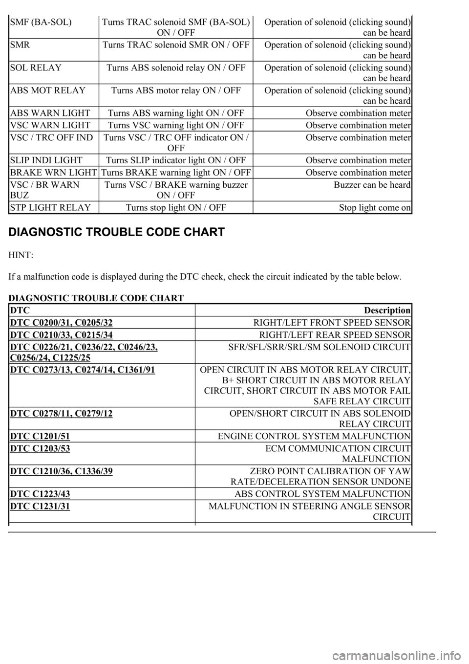
If a malfunction code is displayed during the DTC check, check the circuit indicated by the table below.
DIAGNOSTIC TROUBLE CODE CHART
SMF (BA-SOL)Turns TRAC solenoid SMF (BA-SOL)
ON / OFFOperation of solenoid (clicking sound)
can be heard
SMRTurns TRAC solenoid SMR ON / OFFOperation of solenoid (clicking sound)
can be heard
SOL RELAYTurns ABS solenoid relay ON / OFFOperation of solenoid (clicking sound)
can be heard
ABS MOT RELAYTurns ABS motor relay ON / OFFOperation of solenoid (clicking sound)
can be heard
ABS WARN LIGHTTurns ABS warning light ON / OFFObserve combination meter
VSC WARN LIGHTTurns VSC warning light ON / OFFObserve combination meter
VSC / TRC OFF INDTurns VSC / TRC OFF indicator ON /
OFFObserve combination meter
SLIP INDI LIGHTTurns SLIP indicator light ON / OFFObserve combination meter
BRAKE WRN LIGHTTurns BRAKE warning light ON / OFFObserve combination meter
VSC / BR WARN
BUZTurns VSC / BRAKE warning buzzer
ON / OFFBuzzer can be heard
STP LIGHT RELAYTurns stop light ON / OFFStop light come on
DTCDescription
DTC C0200/31, C0205/32RIGHT/LEFT FRONT SPEED SENSOR
DTC C0210/33, C0215/34RIGHT/LEFT REAR SPEED SENSOR
DTC C0226/21, C0236/22, C0246/23,
C0256/24, C1225/25
SFR/SFL/SRR/SRL/SM SOLENOID CIRCUIT
DTC C0273/13, C0274/14, C1361/91OPEN CIRCUIT IN ABS MOTOR RELAY CIRCUIT,
B+ SHORT CIRCUIT IN ABS MOTOR RELAY
CIRCUIT, SHORT CIRCUIT IN ABS MOTOR FAIL
SAFE RELAY CIRCUIT
DTC C0278/11, C0279/12OPEN/SHORT CIRCUIT IN ABS SOLENOID
RELAY CIRCUIT
DTC C1201/51ENGINE CONTROL SYSTEM MALFUNCTION
DTC C1203/53ECM COMMUNICATION CIRCUIT
MALFUNCTION
DTC C1210/36, C1336/39ZERO POINT CALIBRATION OF YAW
RATE/DECELERATION SENSOR UNDONE
DTC C1223/43ABS CONTROL SYSTEM MALFUNCTION
DTC C1231/31MALFUNCTION IN STEERING ANGLE SENSOR
CIRCUIT
Page 85 of 4500
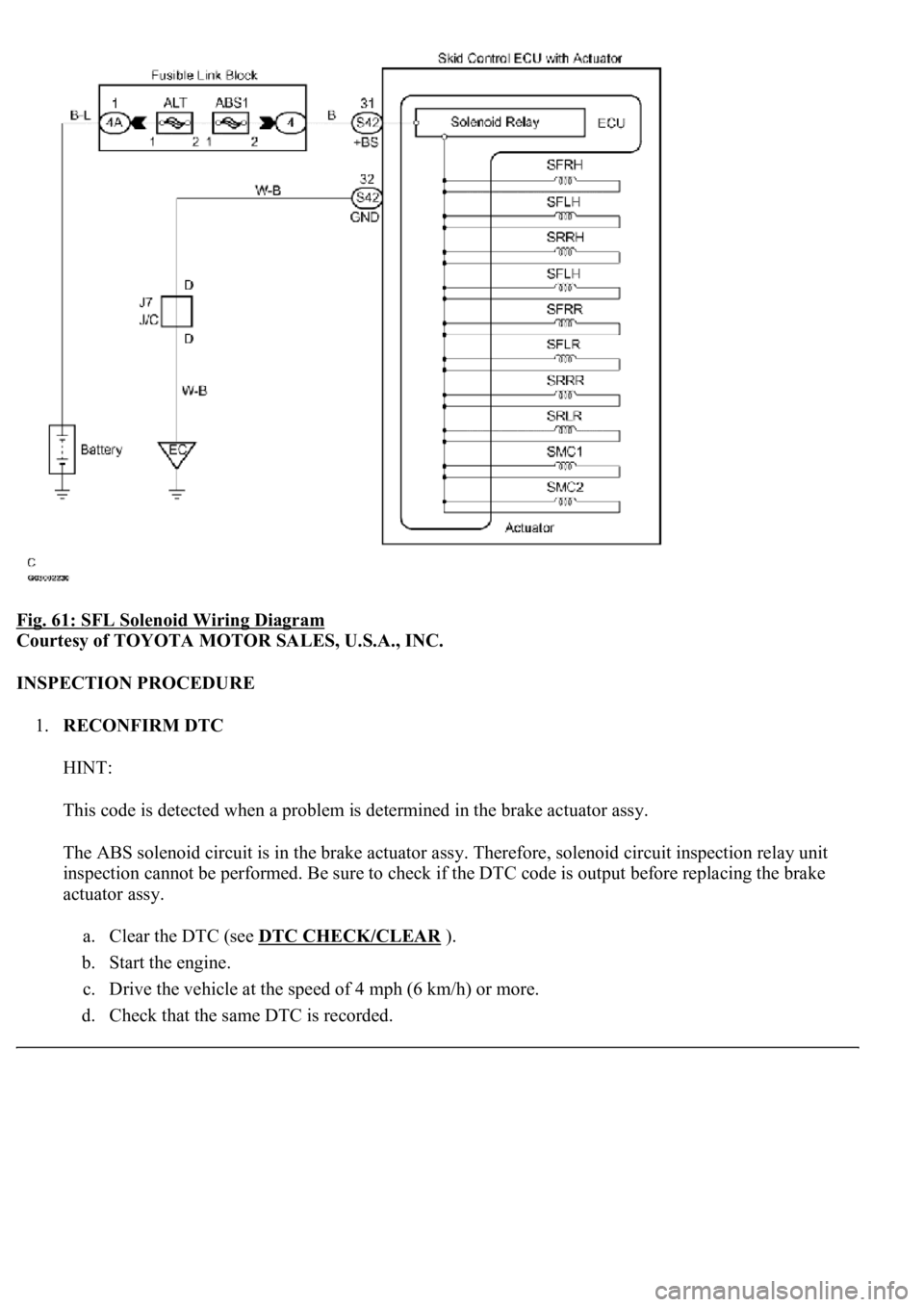
Fig. 61: SFL Solenoid Wiring Diagram
Courtesy of TOYOTA MOTOR SALES, U.S.A., INC.
INSPECTION PROCEDURE
1.RECONFIRM DTC
HINT:
This code is detected when a problem is determined in the brake actuator assy.
The ABS solenoid circuit is in the brake actuator assy. Therefore, solenoid circuit inspection relay unit
inspection cannot be performed. Be sure to check if the DTC code is output before replacing the brake
actuator assy.
a. Clear the DTC (see DTC CHECK/CLEAR
).
b. Start the engine.
c. Drive the vehicle at the speed of 4 mph (6 km/h) or more.
d. Check that the same DTC is recorded.
Page 86 of 4500
OK: Go to next step
The same DTC is recorded.
NG: PROCEED TO NEXT CIRCUIT INSPECTION SHOWN IN PROBLEM SYMPTOMS
TABLE
OK: REPLACE ABS & TRACTION ACTUATOR ASSY (SEE REPLACEMENT
)
CIRCUIT DESCRIPTION
The ABS motor relays consist of 2 relays are included in the engine room No.3 R/B.
The ABS cut relay is turned on after turning the ignition switch to the ON position. If the DTCs in the
ABS pump motor circuit are memorized, the ABS cut relay cuts off the power supply to the ABS motor
relay and performs the fail safe.
While any of the ABS, BA, TRAC and VSC is operating, the skid control ECU (included in the actuator)
<0057005800550051005600030057004b00480003002400250036000300500052005700520055000300550048004f0044005c0003005200510003005700520003005200530048005500440057004800030057004b0048000300440046005700580044005700
52005500030053005800500053000300500052005700520055[.
If the voltage applied to the ABS motor relays (+BM) drops below the condition that detects the DTCs
due to the shorta
ge of the battery or alternator output, the DTCs may be memorized.
Page 88 of 4500
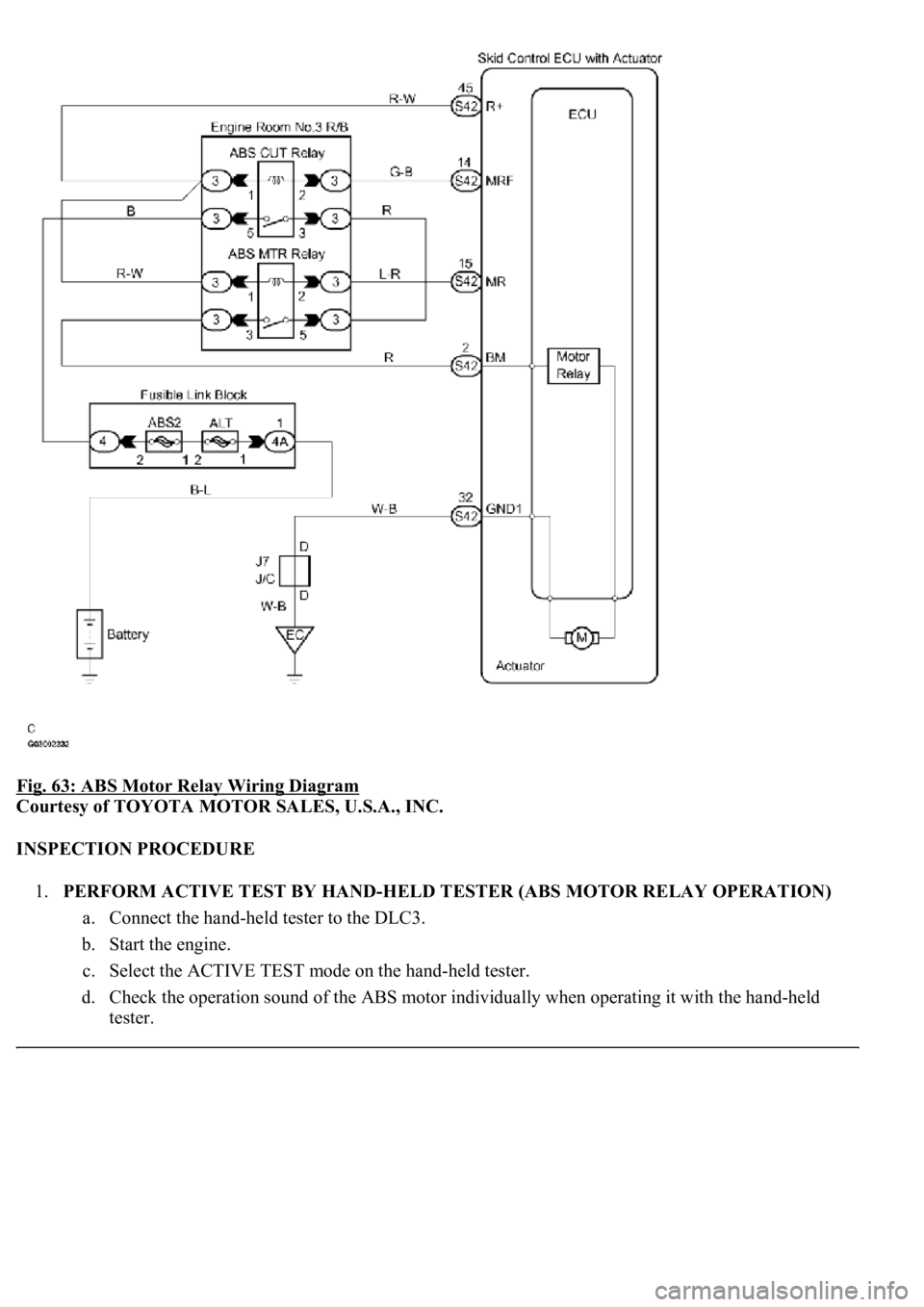
Fig. 63: ABS Motor Relay Wiring Diagram
Courtesy of TOYOTA MOTOR SALES, U.S.A., INC.
INSPECTION PROCEDURE
1.PERFORM ACTIVE TEST BY HAND-HELD TESTER (ABS MOTOR RELAY OPERATION)
a. Connect the hand-held tester to the DLC3.
b. Start the engine.
c. Select the ACTIVE TEST mode on the hand-held tester.
d. Check the operation sound of the ABS motor individually when operating it with the hand-held
tester.
Page 89 of 4500

VEHICLE CONDITION / TEST DETAILS DESCRIPTION
OK: Go to next step
<0037004b00480003005200530048005500440057004c0052005100030056005200580051004700030052004900030057004b0048000300240025003600030050005200570052005500030056004b00520058004f00470003004500480003004b0048004400
5500470011[
NG: Go to step 2
OK: REPLACE ABS & TRACTION ACTUATOR ASSY (SEE REPLACEMENT
)
2.INSPECT FUSE (ABS2 FUSE)
a. Remove the ABS 2 fuse from fusible link block.
b. Measure the resistance according to the value (s) in the table below.
Standard:
ABS 2 FUSE DESCRIPTION
ItemVehicle Condition / Test DetailsVehicle Condition / Test Details
ABS MOT RELAYTurns ABS motor relay / ON or OFFON: Motor relay ON
ABS 2 FuseBelow 1 ohms (Continuity)
Page 91 of 4500
NG: CHECK FOR SHORT IN ALL HARNESS AND CONNECTOR CONNECTED TO FUSE
AND REPLACE FUSE
OK: Go to next step
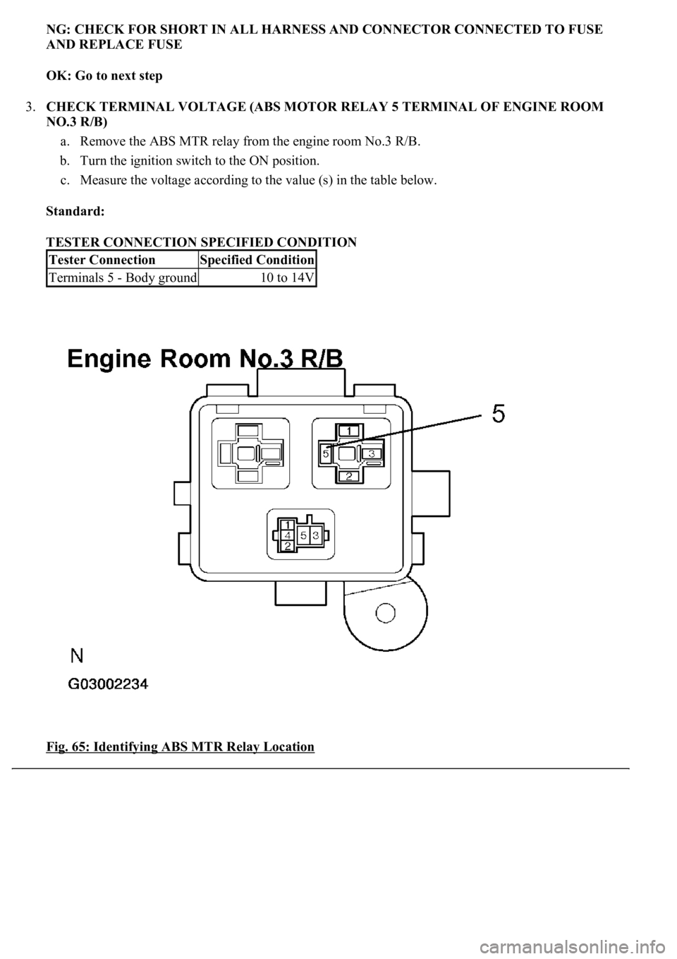
3.CHECK TERMINAL VOLTAGE (ABS MOTOR RELAY 5 TERMINAL OF ENGINE ROOM
NO.3 R/B)
a. Remove the ABS MTR relay from the engine room No.3 R/B.
b. Turn the ignition switch to the ON position.
c. Measure the voltage according to the value (s) in the table below.
Standard:
TESTER CONNECTION SPECIFIED CONDITION
Fig. 65: Identifying ABS MTR Relay Location
Tester ConnectionSpecified Condition
Terminals 5 - Body ground10 to 14V
Page 92 of 4500
Courtesy of TOYOTA MOTOR SALES, U.S.A., INC.
NG: REPAIR OR REPLACE HARNESS OR CONNECTOR
OK: Go to next step
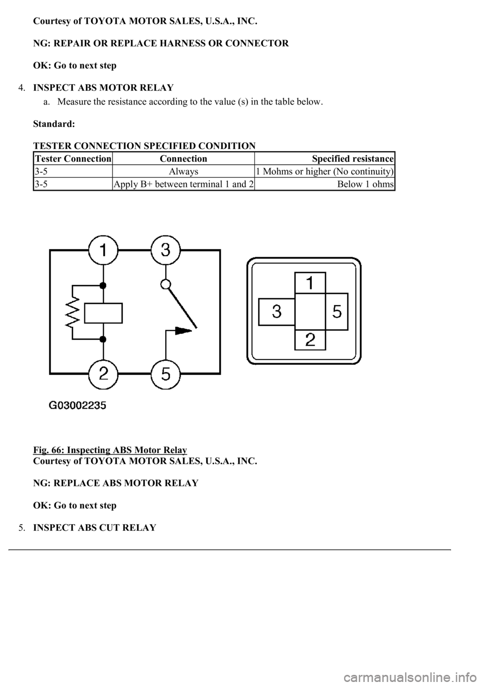
4.INSPECT ABS MOTOR RELAY
a. Measure the resistance according to the value (s) in the table below.
Standard:
TESTER CONNECTION SPECIFIED CONDITION
Fig. 66: Inspecting ABS Motor Relay
Courtesy of TOYOTA MOTOR SALES, U.S.A., INC.
NG: REPLACE ABS MOTOR RELAY
OK: Go to next step
5.INSPECT ABS CUT RELAY
Tester ConnectionConnectionSpecified resistance
3-5Always1 Mohms or higher (No continuity)
3-5Apply B+ between terminal 1 and 2Below 1 ohms