zero point calibration LEXUS LS430 2003 Factory Repair Manual
[x] Cancel search | Manufacturer: LEXUS, Model Year: 2003, Model line: LS430, Model: LEXUS LS430 2003Pages: 4500, PDF Size: 87.45 MB
Page 3 of 4500
When there is a malfunction in the contact point of the terminals or installation problems with parts,
removal and installation of the suspected problem parts may return the system to the normal condition
either completely or temporarily.
In order to determine the malfunctioning area, be sure to check the conditions at the time the malfunction
occurred, such as by DTC output and the freeze frame data output, and record it before disconnecting
each connector or removing and installing parts.
Since the ABS with EBD & BA & TRAC & VSC systems may be influenced by a malfunction in the
other systems, be sure to check for DTCs in the other systems.
Be sure to remove and install the skid control ECU, ABS & TRAC actuator and each sensor with the IG
switch OFF unless specified in the inspection procedure.
When removing and installing the skid control ECU, ABS & TRAC actuator and each sensor, be sure to
check that the normal display is output in test mode inspection and in DTC output inspection after
installing all the parts.
After replacing the yaw rate sensor and/or the brake actuator assembly, make sure to perform yaw rate
sensor and deceleration sensor zero point calibration.
(see CALIBRATION
)
CAN communication system is used for the data communication between the skid control ECU (included
in the actuator), the steering angle sensor, and the yaw rate sensor (the deceleration sensor is included). If
there is trouble in the CAN communication line, the DTC in the communication line is output.
If the DTC in the CAN communication line is output, repair the malfunction in the communication line
and troubleshoot the ABS with EBD & BA & TRAC & VSC systems under the condition that data
communication is normal.
Since the CAN communication line has its own length and route, it can not be repaired temporarily with
the bypass wire, etc.
SYSTEM NAME REFERENCE
System NameSee Procedure
Front Power Seat Control SystemINITIALIZATION
Page 21 of 4500
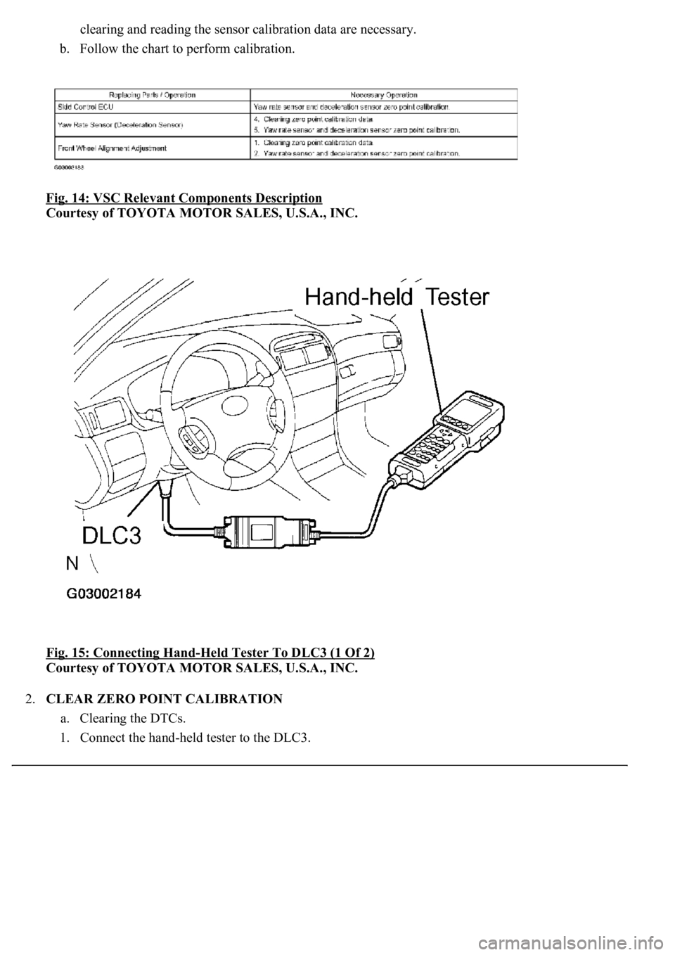
clearing and reading the sensor calibration data are necessary.
b. Follow the chart to perform calibration.
Fig. 14: VSC Relevant Components Description
Courtesy of TOYOTA MOTOR SALES, U.S.A., INC.
Fig. 15: Connecting Hand
-Held Tester To DLC3 (1 Of 2)
Courtesy of TOYOTA MOTOR SALES, U.S.A., INC.
2.CLEAR ZERO POINT CALIBRATION
a. Clearing the DTCs.
1. Connect the han
d-held tester to the DLC3.
Page 22 of 4500
2. Turn the ignition switch to the ON position.
3. Operate the hand-held tester to erase the codes.
HINT:
Refer to the hand-held tester operator's manual for further details.
Check if "VSC" is displayed on the multi-information display.
3.PERFORM ZERO POINT CALIBRATION OF YAW RATE SENSOR AND DECELERATION
SENSOR
a. Check that the steering wheel is in the straight-ahead position and move the shift lever to the P
position.
b. Connect the hand-held tester to the DLC3.
c. Turn the ignition switch to the ON position.
d. Operate the hand-held tester to test mode.
e. Obtain the zero point of the yaw rate sensor and deceleration sensor:
1. Keep the vehicle in the stationar
y condition on a level surface for 2 seconds or more.
Page 24 of 4500
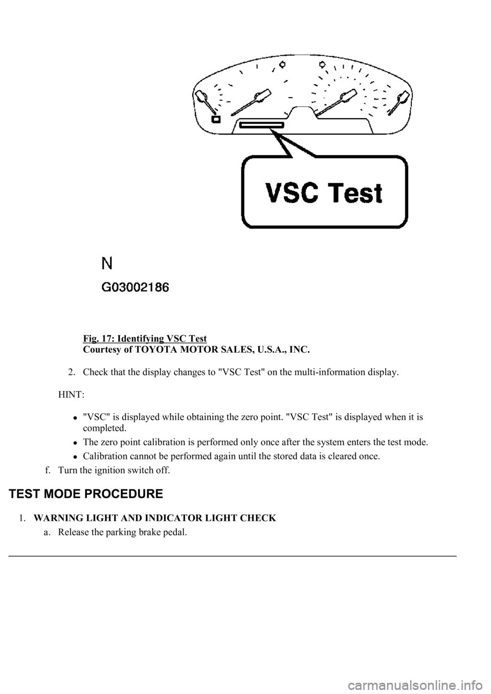
Fig. 17: Identifying VSC Test
Courtesy of TOYOTA MOTOR SALES, U.S.A., INC.
2. Check that the display changes to "VSC Test" on the multi-information display.
HINT:
"VSC" is displayed while obtaining the zero point. "VSC Test" is displayed when it is
completed.
The zero point calibration is performed only once after the system enters the test mode.
Calibration cannot be performed again until the stored data is cleared once.
f. Turn the ignition switch off.
1.WARNING LIGHT AND INDICATOR LIGHT CHECK
a. Release the parking brake pedal.
Page 55 of 4500
HINT:
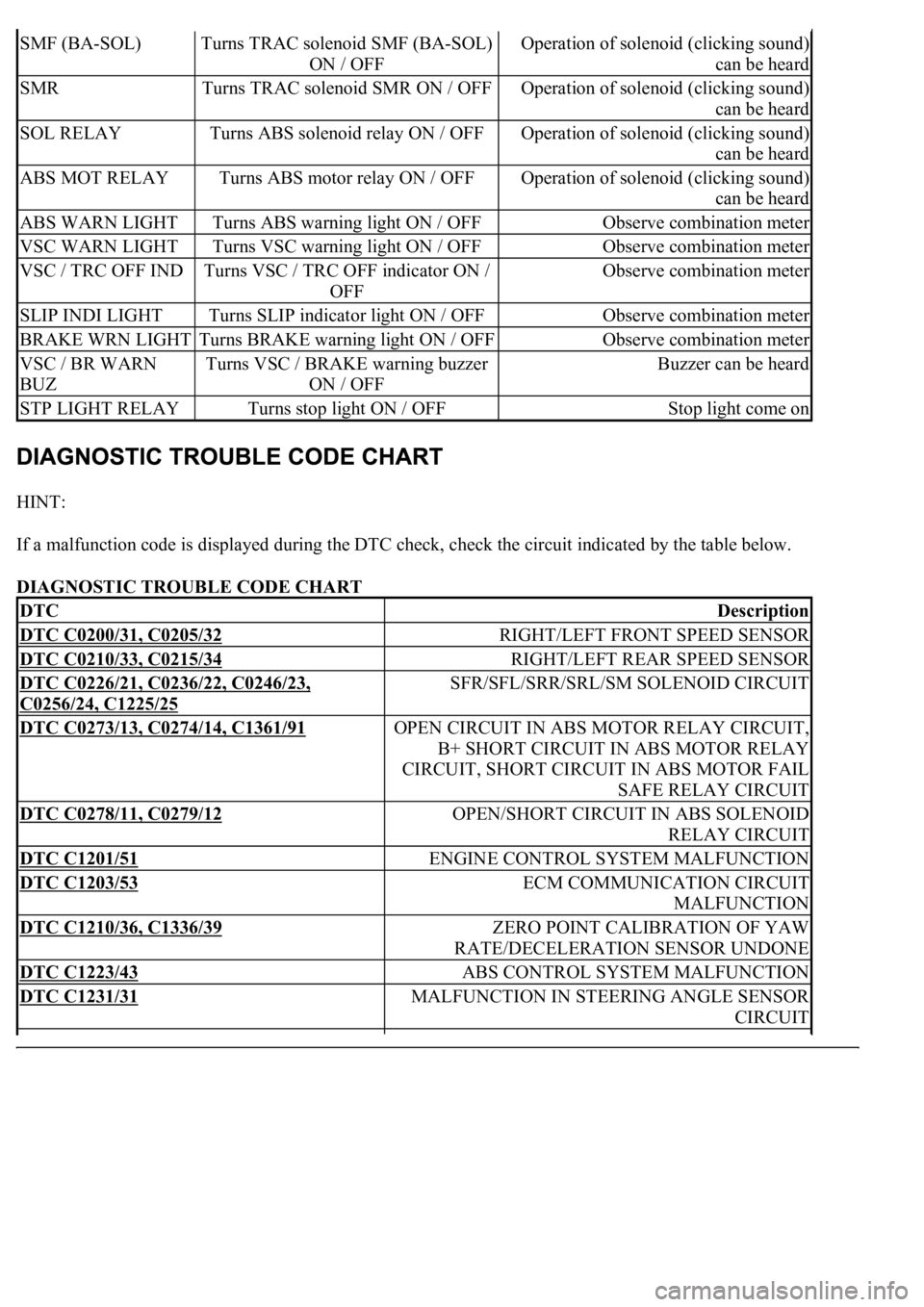
If a malfunction code is displayed during the DTC check, check the circuit indicated by the table below.
DIAGNOSTIC TROUBLE CODE CHART
SMF (BA-SOL)Turns TRAC solenoid SMF (BA-SOL)
ON / OFFOperation of solenoid (clicking sound)
can be heard
SMRTurns TRAC solenoid SMR ON / OFFOperation of solenoid (clicking sound)
can be heard
SOL RELAYTurns ABS solenoid relay ON / OFFOperation of solenoid (clicking sound)
can be heard
ABS MOT RELAYTurns ABS motor relay ON / OFFOperation of solenoid (clicking sound)
can be heard
ABS WARN LIGHTTurns ABS warning light ON / OFFObserve combination meter
VSC WARN LIGHTTurns VSC warning light ON / OFFObserve combination meter
VSC / TRC OFF INDTurns VSC / TRC OFF indicator ON /
OFFObserve combination meter
SLIP INDI LIGHTTurns SLIP indicator light ON / OFFObserve combination meter
BRAKE WRN LIGHTTurns BRAKE warning light ON / OFFObserve combination meter
VSC / BR WARN
BUZTurns VSC / BRAKE warning buzzer
ON / OFFBuzzer can be heard
STP LIGHT RELAYTurns stop light ON / OFFStop light come on
DTCDescription
DTC C0200/31, C0205/32RIGHT/LEFT FRONT SPEED SENSOR
DTC C0210/33, C0215/34RIGHT/LEFT REAR SPEED SENSOR
DTC C0226/21, C0236/22, C0246/23,
C0256/24, C1225/25
SFR/SFL/SRR/SRL/SM SOLENOID CIRCUIT
DTC C0273/13, C0274/14, C1361/91OPEN CIRCUIT IN ABS MOTOR RELAY CIRCUIT,
B+ SHORT CIRCUIT IN ABS MOTOR RELAY
CIRCUIT, SHORT CIRCUIT IN ABS MOTOR FAIL
SAFE RELAY CIRCUIT
DTC C0278/11, C0279/12OPEN/SHORT CIRCUIT IN ABS SOLENOID
RELAY CIRCUIT
DTC C1201/51ENGINE CONTROL SYSTEM MALFUNCTION
DTC C1203/53ECM COMMUNICATION CIRCUIT
MALFUNCTION
DTC C1210/36, C1336/39ZERO POINT CALIBRATION OF YAW
RATE/DECELERATION SENSOR UNDONE
DTC C1223/43ABS CONTROL SYSTEM MALFUNCTION
DTC C1231/31MALFUNCTION IN STEERING ANGLE SENSOR
CIRCUIT
Page 104 of 4500
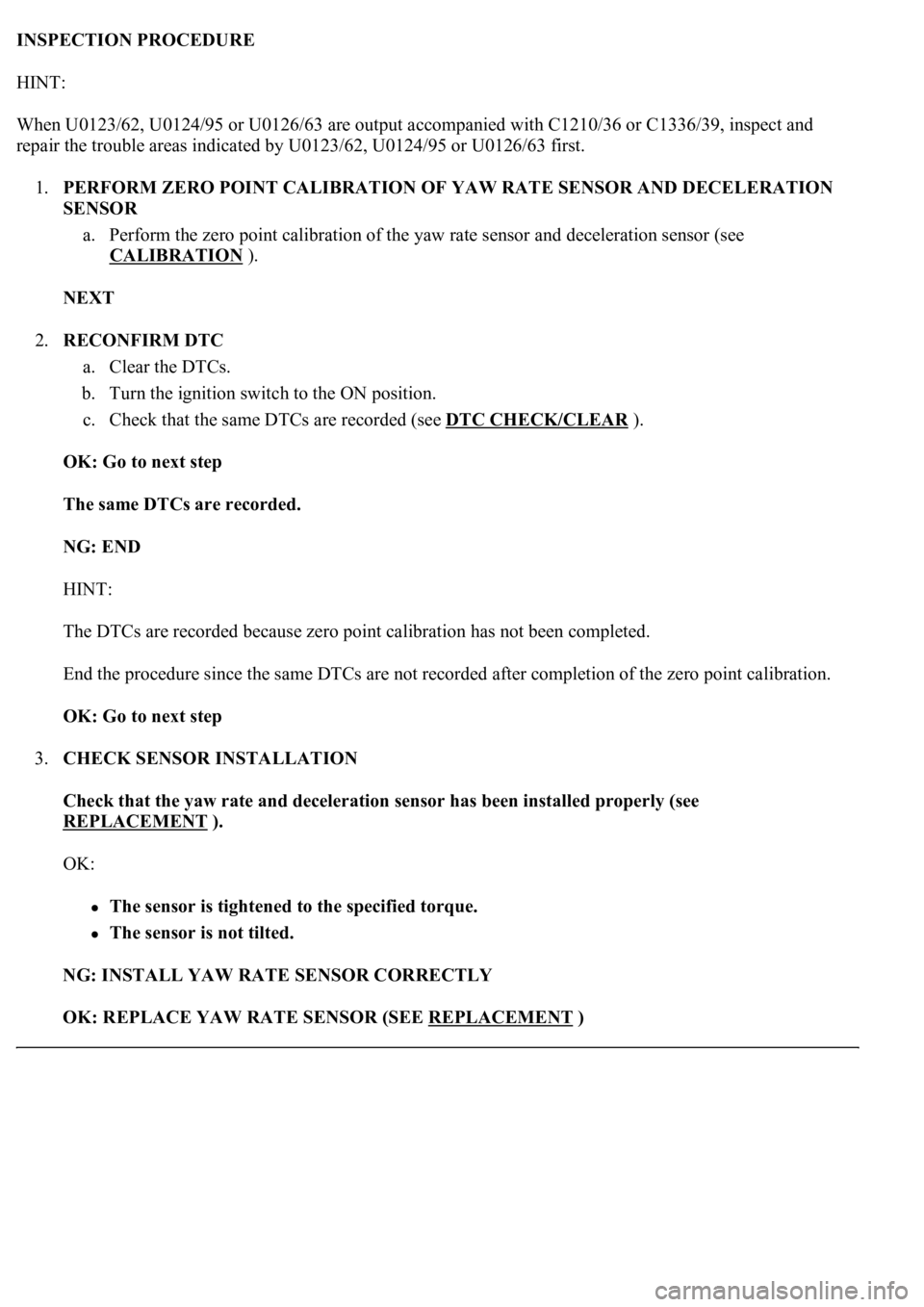
INSPECTION PROCEDURE
HINT:
<003a004b00480051000300380013001400150016001200190015000f0003003800130014001500170012001c001800030052005500030038001300140015001900120019001600030044005500480003005200580057005300580057000300440046004600
520050005300440051004c004800470003005a004c0057004b[ C1210/36 or C1336/39, inspect and
repair the trouble areas indicated by U0123/62, U0124/95 or U0126/63 first.
1.PERFORM ZERO POINT CALIBRATION OF YAW RATE SENSOR AND DECELERATION
SENSOR
a. Perform the zero point calibration of the yaw rate sensor and deceleration sensor (see
CALIBRATION
).
NEXT
2.RECONFIRM DTC
a. Clear the DTCs.
b. Turn the ignition switch to the ON position.
c. Check that the same DTCs are recorded (see DTC CHECK/CLEAR
).
OK: Go to next step
The same DTCs are recorded.
NG: END
HINT:
The DTCs are recorded because zero point calibration has not been completed.
End the procedure since the same DTCs are not recorded after completion of the zero point calibration.
OK: Go to next step
3.CHECK SENSOR INSTALLATION
Check that the yaw rate and deceleration sensor has been installed properly (see
REPLACEMENT
).
OK:
The sensor is tightened to the specified torque.
The sensor is not tilted.
NG: INSTALL YAW RATE SENSOR CORRECTLY
OK: REPLACE YAW RATE SENSOR (SEE REPLACEMENT
)
Page 1084 of 4500
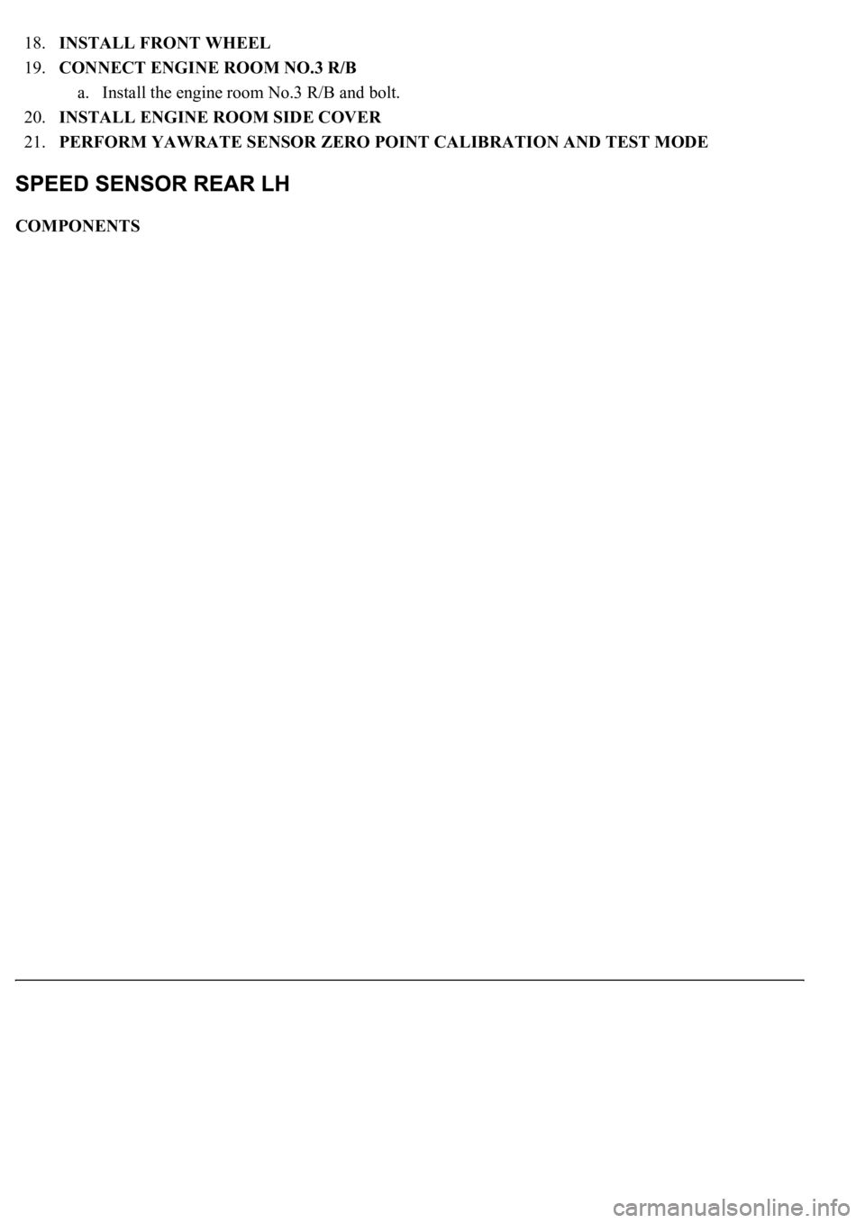
18.INSTALL FRONT WHEEL
19.CONNECT ENGINE ROOM NO.3 R/B
a. Install the engine room No.3 R/B and bolt.
20.INSTALL ENGINE ROOM SIDE COVER
21.PERFORM YAWRATE SENSOR ZERO POINT CALIBRATION AND TEST MODE
COMPONENTS
Page 1104 of 4500
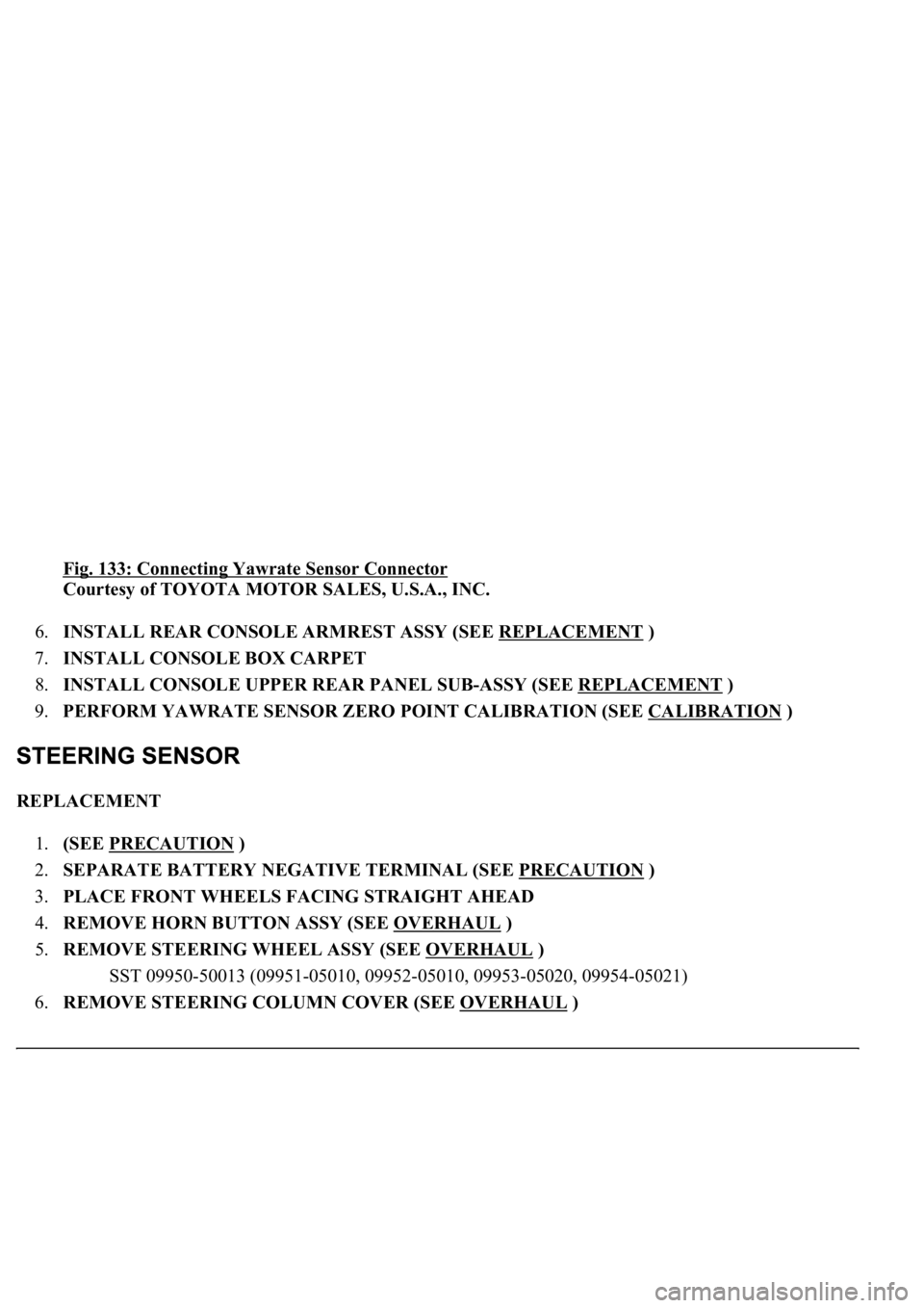
Fig. 133: Connecting Yawrate Sensor Connector
Courtesy of TOYOTA MOTOR SALES, U.S.A., INC.
6.INSTALL REAR CONSOLE ARMREST ASSY (SEE REPLACEMENT
)
7.INSTALL CONSOLE BOX CARPET
8.INSTALL CONSOLE UPPER REAR PANEL SUB-ASSY (SEE REPLACEMENT
)
9.PERFORM YAWRATE SENSOR ZERO POINT CALIBRATION (SEE CALIBRATION
)
REPLACEMENT
1.(SEE PRECAUTION
)
2.SEPARATE BATTERY NEGATIVE TERMINAL (SEE PRECAUTION
)
3.PLACE FRONT WHEELS FACING STRAIGHT AHEAD
4.REMOVE HORN BUTTON ASSY (SEE OVERHAUL
)
5.REMOVE STEERING WHEEL ASSY (SEE OVERHAUL
)
<00360036003700030013001c001c001800130010001800130013001400160003000b0013001c001c00180014001000130018001300140013000f00030013001c001c00180015001000130018001300140013000f00030013001c001c001800160010001300
18001300150013000f00030013001c001c0018001700100013[5021)
6.REMOVE STEERING COLUMN COVER (SEE OVERHAUL
)
Page 1147 of 4500
73.INSPECT PARKING BRAKE PEDAL TRAVEL (SEE ADJUSTMENT )
74.ADJUST PARKING BRAKE PEDAL TRAVEL (SEE ADJUSTMENT
)
75.INSTALL INSTRUMENT PANEL UNDER COVER SUB-ASSY NO.2 (SEE REPLACEMENT
)
76.INSTALL INSTRUMENT PANEL AIR BAG ASSY LOWER NO.1 (SEE REPLACEMENT
)
77.INSTALL INSTRUMENT PANEL SAFETY PAD SUB-ASSY NO.1 (SEE REPLACEMENT
)
78.INSTALL OUTER MIRROR SWITCH ASSY
79.INSTALL COIN BOX ASSY
80.INSTALL INSTRUMENT PANEL UNDER COVER SUB-ASSY NO.1 (SEE REPLACEMENT
)
81.INSTALL INSTRUMENT CLUSTER FINISH PANEL CENTER LOWER
82.INSTALL INSTRUMENT CLUSTER FINISH PANEL END
83.CONNECT BATTERY NEGATIVE TERMINAL
84.INSPECT SRS WARNING LIGHT (SEE DIAGNOSIS SYSTEM
)
85.CHECK FOR EXHAUST GAS LEAKS
86.PERFORM YAWRATE SENSOR ZERO POINT CALIBRATION (SEE CALIBRATION
)
87.PERFORM INITIALIZATION (SEE INITIALIZATION
)
COMPONENTS
Page 2414 of 4500
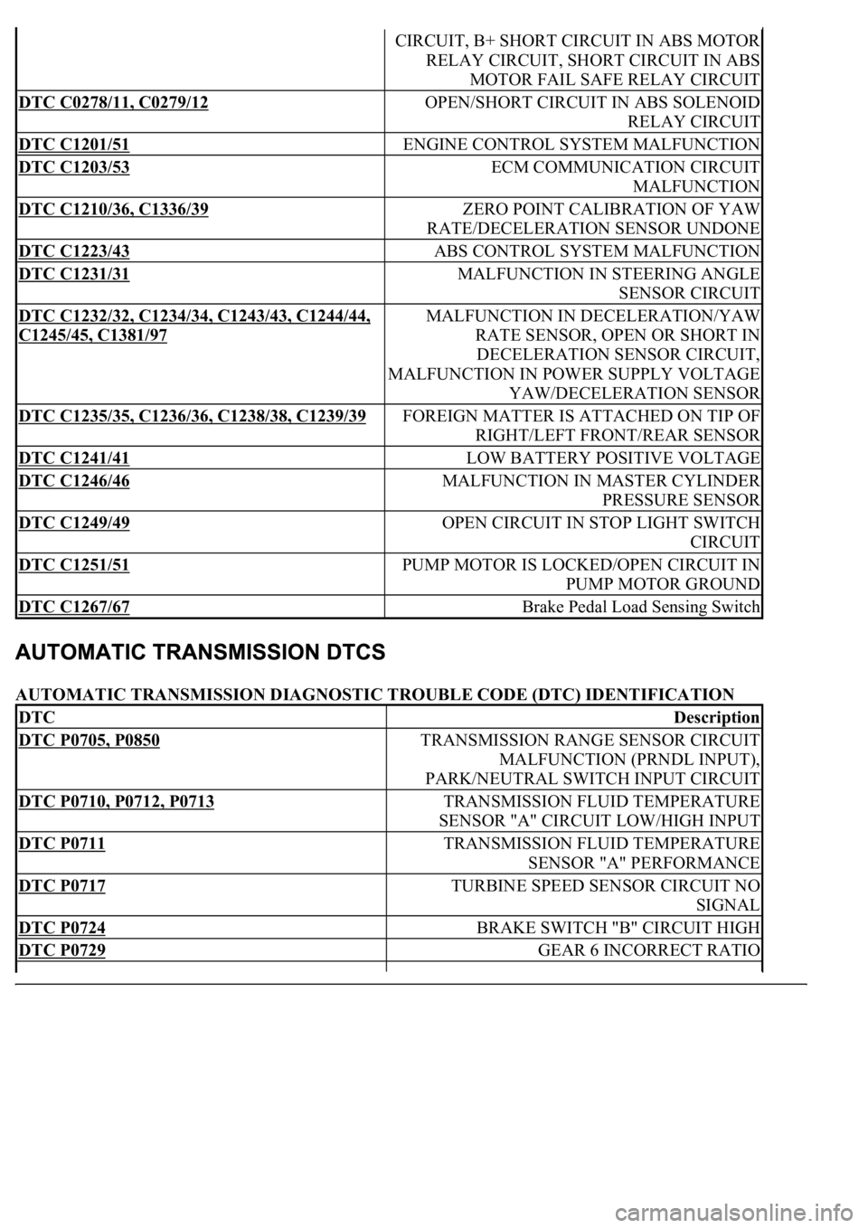
AUTOMATIC TRANSMISSION DIAGNOSTIC TROUBLE CODE (DTC) IDENTIFICATION
CIRCUIT, B+ SHORT CIRCUIT IN ABS MOTOR
RELAY CIRCUIT, SHORT CIRCUIT IN ABS
MOTOR FAIL SAFE RELAY CIRCUIT
DTC C0278/11, C0279/12 OPEN/SHORT CIRCUIT IN ABS SOLENOID
RELAY CIRCUIT
DTC C1201/51 ENGINE CONTROL SYSTEM MALFUNCTION
DTC C1203/53 ECM COMMUNICATION CIRCUIT
MALFUNCTION
DTC C1210/36, C1336/39 ZERO POINT CALIBRATION OF YAW
RATE/DECELERATION SENSOR UNDONE
DTC C1223/43 ABS CONTROL SYSTEM MALFUNCTION
DTC C1231/31 MALFUNCTION IN STEERING ANGLE
SENSOR CIRCUIT
DTC C1232/32, C1234/34, C1243/43, C1244/44,
C1245/45, C1381/97
MALFUNCTION IN DECELERATION/YAW
RATE SENSOR, OPEN OR SHORT IN
DECELERATION SENSOR CIRCUIT,
MALFUNCTION IN POWER SUPPLY VOLTAGE
YAW/DECELERATION SENSOR
DTC C1235/35, C1236/36, C1238/38, C1239/39 FOREIGN MATTER IS ATTACHED ON TIP OF
RIGHT/LEFT FRONT/REAR SENSOR
DTC C1241/41 LOW BATTERY POSITIVE VOLTAGE
DTC C1246/46 MALFUNCTION IN MASTER CYLINDER
PRESSURE SENSOR
DTC C1249/49 OPEN CIRCUIT IN STOP LIGHT SWITCH
CIRCUIT
DTC C1251/51 PUMP MOTOR IS LOCKED/OPEN CIRCUIT IN
PUMP MOTOR GROUND
DTC C1267/67 Brake Pedal Load Sensing Switch
DTCDescription
DTC P0705, P0850 TRANSMISSION RANGE SENSOR CIRCUIT
MALFUNCTION (PRNDL INPUT),
PARK/NEUTRAL SWITCH INPUT CIRCUIT
DTC P0710, P0712, P0713 TRANSMISSION FLUID TEMPERATURE
SENSOR "A" CIRCUIT LOW/HIGH INPUT
DTC P0711 TRANSMISSION FLUID TEMPERATURE
SENSOR "A" PERFORMANCE
DTC P0717 TURBINE SPEED SENSOR CIRCUIT NO
SIGNAL
DTC P0724 BRAKE SWITCH "B" CIRCUIT HIGH
DTC P0729 GEAR 6 INCORRECT RATIO