high LEXUS RCF 2022 Owners Manual
[x] Cancel search | Manufacturer: LEXUS, Model Year: 2022, Model line: RCF, Model: LEXUS RCF 2022Pages: 412, PDF Size: 26.28 MB
Page 5 of 412

3TABLE OF CONTENTS
RC F Owner's Manual
1
2
3
4
5
6
7
8
9
Automatic transmission..............132
Turn signal lever............................. 136
Parking brake ................................. 137
ASC (Active Sound Control) .. 137
4-3. Operating the lights and wipers Headlight switch ............................ 138
AHB (Automatic High Beam) ............................................................ 140
Windshield wipers and washer ............................................................ 143
4-4. Refueling Opening the fuel tank cap......... 150
4-5. Using the driving support systems Lexus Safety System + ................ 153
PCS (Pre-Collision System)..... 157
LDA (Lane Departure Alert with steering control) ......................... 164
Dynamic radar cruise control ... 171
BSM (Blind Spot Monitor) ........ 179
Intuitive parking assist ................. 186
Driving mode select switch....... 192
Launch control ............................... 193
Active rear wing ............................ 195
TVD (Torque Vect oring Differen-
tial) .................................................... 197
Driving assist systems.................. 199
4-6. Driving tips Winter driving tips ....................... 203
5-1. Remote Touch/Display Remote Touch ............................... 206
Center Display .............................. 2085-2. Using the air conditioning system
Automatic air conditioning system............................................................. 211
Heated steering wheel/seat heat- ers/seat ventilators..................... 219
5-3. Using the interior lights Interior lights list ............................. 221
5-4. Using the storage features List of storage features ............... 223
Trunk features ................................ 225
5-5. Using the other interior features Other interior features ............... 226
Garage door opener ..................229
Compass ......................................... 234
6-1. Maintenance and care Cleaning and protecting the vehi-cle exterior................................... 238
Cleaning and protecting the vehi- cle interior .................................... 243
6-2. Matte paint care guide (if equipped)
Basic knowledge about matte clear coat .................................................. 247
Washing your vehicle ................. 251
Frequently Asked Questions ........................................................... 252
6-3. Maintenance Maintenance re quirements .....255
General maintenance................ 256
Emission inspection and mainte- nance (I/M) programs ............ 259
6-4. Do-it-yourself maintenance Do-it-yourself service precautions.......................................................... 260
5Interior features
6Maintenance and care
Page 18 of 412

16Pictorial index
RC F Owner's Manual
■Switches
Automatic High Beam switch..............................................................................P.140
Windshield wiper de-icer switch
*...................................................................... P.215
Active rear wing switch
*....................................................................................... P.195
Odometer/trip meter/trip meter reset button ............................................... P.72
Instrument panel light control switches ............................................................. P.73
Intuitive parking assist switch
*............................................................................ P.186
BSM (Blind Spot Monitor) main switch ............................................................ P.179
*:If equipped
Driving position memory buttons
*.....................................................................P.105
A
B
C
D
E
F
G
A
Page 24 of 412

221-1. For safe use
RC F Owner's Manual
1-1.For safe use
Use only floor mats designed specifi-
cally for vehicles of the same model
and model year as your vehicle. Fix
them securely in place onto the carpet.
1Insert the retaining hooks (clips)
into the floor mat eyelets.
2 Turn the upper knob of each retain-
ing hook (clip) to secure the floor
mats in place.
Always align the marks.
The shape of the reta ining hooks (clips)
may differ from that shown in the illustra-
tion.
Before driving
Observe the following before start-
ing off in the vehicle to ensure
safety of driving.
Installing floor mats
A
WARNING
Observe the following precautions.
Failure to do so may cause the driver’s
floor mat to slip, possibly interfering with
the pedals while driving. An unexpect-
edly high speed may result or it may
become difficult to stop the vehicle. This
could lead to an accident, resulting in
death or serious injury.
■When installing the driver’s floor mat
●Do not use floor mats designed for
other models or di fferent model year
vehicles, even if they are Lexus Genu-
ine floor mats.
●Only use floor mats designed for the
driver’s seat.
●Always install the floor mat securely
using the retaining hooks (clips) pro-
vided.
●Do not use two or more floor mats on
top of each other.
●Do not place the floor mat bot-
tom-side up or upside-down.
■Before driving
●Check that the floor mat is securely
fixed in the correct place with all the
provided retaining hooks (clips). Be
especially careful to perform this
check after cleaning the floor.
●With the engine stopped and the shift
lever in P, fully depress each pedal to
the floor to make sure it does not inter-
fere with the floor mat.
Page 32 of 412

301-1. For safe use
RC F Owner's Manual
shown in the system components diagram above. This information includes crash
severity and occupant information. As the airbags deploy, a chemical reaction in
the inflators quickly fills the airbags with no n-toxic gas to help restrain the motion of
the occupants.
■If the SRS airbags deploy (inflate)
●Slight abrasions, burns, bruising etc., may
be sustained from SRS airbags, due to the
extremely high speed deployment (infla-
tion) by hot gases.
●A loud noise and white powder will be
emitted.
●Parts of the airbag module (steering
wheel hub, airbag cover and inflator) as
well as the front seat s, parts of the front
and rear pillars, and roof side rails, may
be hot for several minutes. The airbag
itself may also be hot.
●The windshield may crack.
●For Lexus Enform Safety Connect sub-
scribers, if the SRS airbags deploy or in
the event of a severe rear-end collision,
the system is designed to send an emer-
gency call to the response center, notify-
ing them of the vehicle’s location (without
needing to push the “SOS” button) and
an agent will attempt to speak with the
occupants to ascertain the level of emer-
gency and assistance required. If the
occupants are unable to communicate,
the agent automatically treats the call as
an emergency and help s to dispatch the
necessary emergency services. ( P.53)
■SRS airbag deployment conditions (SRS
front airbags)
●The SRS front airbags will deploy in the
event of an impact that exceeds the set
threshold level (the le vel of force corre-
sponding to an approximately 12 - 18
mph [20 - 30 km/h] frontal collision with
a fixed wall that does not move or
deform).
However, this threshold velocity will be
considerably higher in the following situa-
tions:
• If the vehicle strikes an object, such as a parked vehicle or sign pole, which can
move or deform on impact
• If the vehicle is involved in an underride collision, such as a collision in which the
front of the vehicle “u
nderrides”, or goes
under, the bed of a truck
●Depending on the type of collision, it is
possible that only the seat belt
pretensioners will activate.
●The SRS front airbags for the front pas-
senger will not activate if there is no pas-
senger sitting in the front passenger seat.
However, the SRS front airbags for the
front passenger may deploy if luggage is
put in the seat, even if the seat is unoccu-
pied.
■SRS airbag deployment conditions (SRS
side and curtain shield airbags)
●The SRS side and curtain shield airbags
will deploy in the event of an impact that
exceeds the set threshold level (the level
of force corresponding to the impact
force produced by an approximately
3300 lb. [1500 kg] vehicle colliding with
the vehicle cabin from a direction per-
pendicular to the vehicle orientation at an
approximate speed of 12 - 18 mph [20 -
30 km/h]).
●The SRS curtain shield airbags will deploy
in the event of vehicle rollover.
●The SRS side and curtain shield airbags
will deploy in the event of a severe frontal
collision.
■Conditions under which the SRS
airbags may deploy (inflate), other than
a collision
The SRS front airbags and SRS side and
curtain shield airbags may also deploy if a
serious impact occurs to the underside of
your vehicle. Some examples are shown in
the illustration.
●Hitting a curb, edge of pavement or hard
surface
●Falling into or jumping over a deep hole
●Landing hard or falling
Page 35 of 412

331-1. For safe use
RC F Owner's Manual
1
For safety and security
WARNING
●The SRS driver airbag deploys with
considerable force, and can cause
death or serious injury especially if the
driver is very close to the airbag. The
National Highway Traffic Safety
Administration (NHTSA) advises:
Since the risk zone for the driver’s
airbag is the first 2 - 3 in. (50 - 75 mm)
of inflation, placing yourself 10 in. (250
mm) from your driver airbag provides
you with a clear margin of safety. This
distance is measured from the center
of the steering wheel to your breast-
bone. If you sit less than 10 in. (250
mm) away now, you can change your
driving position in several ways:
• Move your seat to the rear as far as you can while still reaching the pedals
comfortably.
• Slightly recline the back of the seat. Although vehicle designs vary, many
drivers can achieve the 10 in. (250
mm) distance, even with the driver seat
all the way forward, simply by reclining
the back of the seat somewhat. If
reclining the back of your seat makes it
hard to see the road, raise yourself by
using a firm, non-slip pery cushion, or
raise the seat if your vehicle has that
feature.
• If your steering wheel is adjustable, tilt it downward. This points the airbag
toward your chest instead of your head
and neck.
The seat should be adjusted as recom-
mended by NHTSA above, while still
maintaining control of the foot pedals,
steering wheel, and your view of the
instrument panel controls.
●If the seat belt extender has been con-
nected to the front seat belt buckles
but the seat belt extender has not also
been fastened to the latch plate of the
seat belt, the SRS front airbags will
judge that the driver and front passen-
ger are wearing the seat belt even
though the seat belt has not been con-
nected. In this case, the SRS front
airbags may not activate correctly in a
collision, resulting in death or serious
injury in the event of a collision. Be
sure to wear the seat belt with the seat
belt extender.
●The SRS front passenger airbag also
deploys with consid erable force, and
can cause death or serious injury
especially if the front passenger is very
close to the airbag. The front passen-
ger seat should be as far from the
airbag as possible with the seatback
adjusted, so the front passenger sits
upright.
●Improperly seated and/or restrained
infants and children can be killed or
seriously injured by a deploying airbag.
An infant or child who is too small to
use a seat belt should be properly
secured using a child restraint system.
Lexus strongly recommends that all
infants and children be placed in the
rear seats of the vehicle and properly
restrained. The rear seats are safer for
infants and children than the front pas-
senger seat. (
P.42)
Page 50 of 412

481-2. Child safety
RC F Owner's Manual
■Booster seat
1 If installing the child restraint sys-
tem to the front passenger seat is
unavoidable, refer to P.44for front
passenger seat adjustment.
2 Place the child restraint system on
the seat facing the front of the vehi-
cle.
Booster type
High back type
3 Sit the child in the child restraint
system. Fit the seat belt to the child
restraint system according to the
manufacturer’s in structions and
insert the plate into the buckle.
Make sure that the belt is not
twisted.
Check that the shoulder belt is correctly
positioned over the child’s shoulder and
that the lap belt is as low as possible. (
P.24)
■Removing a child restraint system
installed with a seat belt
Press the buckle release button and
fully retract the seat belt.
When releasing the buckle, the child
restraint system may sp ring up due to the
rebound of the seat cushion. Release the
buckle while holding down the child
restraint system.
Since the seat belt auto matically reels itself,
slowly return it to the stowing position.
WARNING
■When installing a child restraint sys-
tem
Observe the following precautions.
Failure to do so may result in death or
serious injury.
Page 64 of 412

622-1. Instrument cluster
RC F Owner's Manual
2-1.Instrument cluster
For the purpose of explanation, the following illustrations display all warning lights
and indicators illuminated.
The units used on the meters and some indicators may differ depending on the target
region.
Warning lights inform the driver of mal-
functions in the indicated vehicle sys-
tems.
Warning lights and indicators
The warning lights and indicators on th e instrument cluster, center panel and
outside rear view mirrors inform the driver of the status of the vehicle’s various
systems.
Warning lights and indicators displayed on the instrument cluster
Warning lights
(U.S.A.)
Brake system warning light*1
( P.300)
(Canada)
Brake system warning light*1
( P.300)
High coolant temperature
warning light
*2 ( P.300)
Charging system warning
light
*1, 2 (P.300)
Low engine oil pressure warn-
ing light
*2 ( P.301)
(U.S.A.)
Malfunction indicator lamp*1
( P.301)
(Canada)
Malfunction indicator lamp*1
( P.301)
SRS warning light
*1 ( P.301)
Page 65 of 412
632-1. Instrument cluster
RC F Owner's Manual
2
Vehicle status information and indicators
*1: These lights turn on when the engine switch is turned to IGNITION ON
mode to indicate that a system check is
being performed. They will turn off after
the engine is started,
or after a few sec-
onds. There may be a malfunction in a
system if a light does not come on, or
turn off. Have the vehicle inspected by
your Lexus dealer.
*2: This light illuminates on the multi-infor- mation display.
*3: This light illuminates on the center panel.
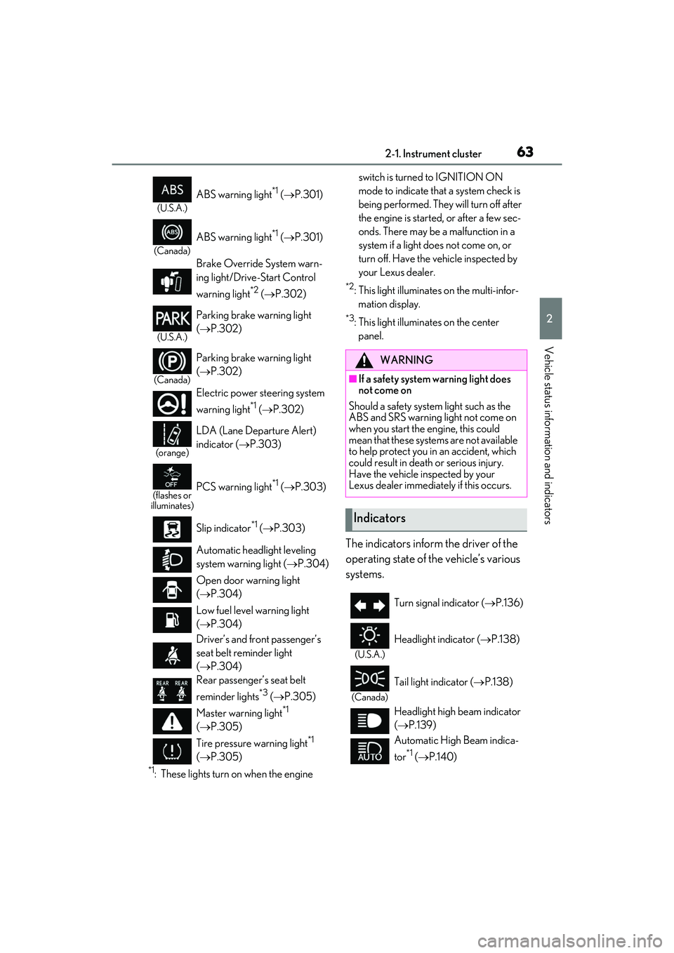
The indicators inform the driver of the
operating state of the vehicle’s various
systems.
(U.S.A.)
ABS warning light*1 ( P.301)
(Canada)
ABS warning light*1 ( P.301)
Brake Override System warn-
ing light/Drive-Start Control
warning light
*2 ( P.302)
(U.S.A.)
Parking brake warning light
(P.302)
(Canada)
Parking brake warning light
(P.302)
Electric power st eering system
warning light
*1 ( P.302)
(orange)
LDA (Lane Departure Alert)
indicator ( P.303)
(flashes or
illuminates)PCS warning light*1 ( P.303)
Slip indicator
*1 ( P.303)
Automatic headlight leveling
system warning light ( P.304)
Open door warning light
( P.304)
Low fuel level warning light
( P.304)
Driver’s and front passenger’s
seat belt reminder light
( P.304)
Rear passenger’s seat belt
reminder lights
*3 ( P.305)
Master warning light
*1
( P.305)
Tire pressure warning light
*1
( P.305)
WARNING
■If a safety system warning light does
not come on
Should a safety system light such as the
ABS and SRS warning light not come on
when you start the engine, this could
mean that these systems are not available
to help protect you in an accident, which
could result in death or serious injury.
Have the vehicle inspected by your
Lexus dealer immediat ely if this occurs.
Indicators
Turn signal indicator (P.136)
(U.S.A.)
Headlight indicator (P.138)
(Canada)
Tail light indicator ( P.138)
Headlight high beam indicator
( P.139)
Automatic High Beam indica-
tor
*1 ( P.140)
Page 73 of 412

712-1. Instrument cluster
RC F Owner's Manual
2
Vehicle status information and indicators
■Rev peak (Normal mode/SPORT
S mode)
The engine speed reaches or exceeds
3600 rpm, an afterimage of the
tachometer will be displayed at the
highest engine speed for approxi-
mately 1 second.
■Meter display and layout
If the drive mode is changed, some of
the meter displays and the gauge lay-
out will be changed. ( P.192)
■The meters and display illuminate when
The engine switch is in IGNITION ON
mode.
■Welcome illumination of the analog
speedometer
●When the driver’s door is opened, the
analog speedometer will illuminate. Then,
when the driver’s door is closed, the ana-
log speedometer will illuminate and go
off (pulsate) 3 times.
●In the following situations, the analog
speedometer will not pulsate even
though the driver’s door is opened and
closed:
• Within 60 seconds after the analog
meter pulsation completes
• Within 60 seconds of turning the engine switch off
■Variable red zone
To help protect the engine, the engine
speed is controlled by starting the red zone
of the tachometer at different engine
speeds ranging from 3700 rpm to 7300
rpm depending on the engine coolant tem-
perature. Before driving under extremely
high load conditions, make sure to suffi-
ciently warm up the engine.
■Eco driving meter
●The number of blue segments displayed
on the eco driving meter
decreases/increases depending on the
vehicle acceleration. Use this meter as a
guideline when you wish to drive in an
eco-friendly manner that reduces fuel
consumption.
However, on a downward grade where
the vehicle can accelerate without the
accelerator pedal being depressed, the
eco driving meter ma y not display the
eco-driving state correctly.
●When the shift lever is moved to P, N or
R, the segments will turn gray and the eco
driving meter will not operate.
■Dimming the analog speedometer
lighting
The analog speedometer lighting will be
dimmed when the ambient light is bright,
such as during the daytime, and SPORT S
or SPORT S+ mode is selected.
■Outside temperature display
●In the following situations, the correct
outside temperature may not be dis-
played, or the display may take longer
than normal to change:
• When stopped, or driving at low speeds (less than 12 mph [20 km/h])
• When the outside temperature has
Changing the display
Page 78 of 412

762-1. Instrument cluster
RC F Owner's Manual
• After start: Displays elapsed time since engine start
Distance
• Driving range: Displays driving range
with remaining fuel
*3, 4
• After start: Displays drive distance since vehicle start
Other
Blank: No item
*1:Resetting: P.75
*2: Use the displayed fuel consumption as a
reference.
*3: When only a small amount of fuel is added to the tank, the display may not
be updated.
When refueling, turn the engine switch
off. If the vehicle is refueled without
turning the engine switch off, the display
may not be updated.
*4: This distance is computed based on
your average fuel consumption. As a
result, the actual distance that can be
driven may differ from that displayed.
■Eco Driving Indicator
During Eco-friendly acceleration (Eco
driving), the Eco Driving Indicator
Light will turn on.
When the acceleration exceeds the
Zone of Eco driving, or when the vehi-
cle is stopped, the light turns off. Eco Driving Indicator will not operate
under the following conditions:
The shift lever is in any position
other than D.
A paddle shift switch is operated.
Neither normal mode nor Eco drive
mode is selected. ( P.192)
The vehicle speed is approximately
80 mph (130 km/h) or higher.
■Tire pressure
P.273
■Gear positions
Displays the current gear position
when the shift lever is in D or M.
■Vehicle sway warning
Detects the sway of the vehicle within a
lane, which is often associated with a
decrease in the driver’s attention level,
and displays the decrease in attention
using a bar display.
The shorter the bar length, the more
the driver may need to rest.
This display is a pa rt of the LDA (Lane
Departure Alert with steering control) sys-
tem. The display is enabled when the oper-
ating conditions of the vehicle sway
warning are met. ( P.165)
■Units
The units of measure used can be
changed while driving.
Unlike the units setting performed on ,
the units setting performed on can be
changed while driving.
■Blank (No items)
Displays no drive information contents.