LEXUS SC400 1991 Service Repair Manual
Manufacturer: LEXUS, Model Year: 1991, Model line: SC400, Model: LEXUS SC400 1991Pages: 4087, PDF Size: 75.75 MB
Page 1001 of 4087

2. REMOVE CALIPER
(a) Hold the sliding pin and loosen the 2 installation bolts.
(b) Remove the 2 installation bolts.
(c) Remove the caliper from the torque plate.
3. REMOVE FOLLOWING PARTS:
(a) 2 anti±squeal springs
(b) 2 brake pads
CALIPER DISASSEMBLY
BR043±0B
1. REMOVE CYLINDER BOOT SET RINGS AND CYLINDERBOOT
Using a screwdriver, remove the 2 cylinder boot set rings and
cylinder boots from the caliper.
2. REMOVE PISTONS
(a) Place a piece of cloth or similar article between the piston and
the caliper.
(b) Use compressed air to remove the pistons from the caliper.
CAUTION: Do not place your fingers in front of the piston when
using compressed air.
3. REMOVE PISTON SEALS Using a screwdriver, remove the piston seal from the caliper.
BR±32
±
BRAKE SYSTEM FRONT BRAKE (SC400)
WhereEverybodyKnowsYourName
Page 1002 of 4087

4. REMOVE SLIDING PINS AND DUST BOOTS
(a) Remove the 2 sliding pins from the torque plate.
(b) Using a screwdriver and hammer, tap out the 2 dust boots.
FRONT BRAKE COMPONENTS
INSPECTION AND REPAIR
BR044±08
1. MEASURE PAD LINING THICKNESSUsing a ruler, measure the pad lining thickness.
Standard thickness:
11.0 mm (0.433 in.)
Minimum thickness: 1.0 mm (0.039 in.)
Replace the pad if the pad's thickness is at the minimum
thickness or less, or if the pad has severely uneven wear.
2. MEASURE DISC THICKNESS Using a micrometer, measure the disc thickness.
Standard thickness:
32 mm (1.260 in.)
Minimum thickness: 30 mm (1.181 in.)
Replace the disc if the thickness of the disc is at the minimum
thickness or less. Replace the disc or grind it on a lathe if it
is scored or is worn unevenly.
±
BRAKE SYSTEM FRONT BRAKE (SC400)BR±33
WhereEverybodyKnowsYourName
Page 1003 of 4087

3. MEASURE DISC RUNOUTUsing a dial indicator, measure the disc runout at a position
10 mm (0.39 in.) from the outside edge.
Maximum disc runout:
0.05 mm (0.0020 in.)
If the disc's runout is at the maximum value or greater, check
the bearing play in the axial direction and check the axle hub
runout (See page SA±30). If the bearing play and axle hub
runout are not abnormal, adjust the disc runout.
4. IF NECESSARY, ADJUST DISC RUNOUT
(a) Remove the 2 bolts and torque plate from the knuckle.
(b) Remove the hub nuts and the disc. Reinstall the disc 1/5 of a turn round from its original position on the hub. Install and
torque the hub nuts.
Torque: 103 N Vm (1,050 kgf Vcm, 76 ft Vlbf)
Remeasure the disc runout. Make a not of the runout and
disc's position on the hub.
(c) Repeat (b) until the disc has been install on the 3 remaining hub position.
(d) If the minimum runout recorded in (b) and (c) is less than 0.05
mm (0.0020 in.), install the disc in that position.
(e) If the minimum runout recorded in (b) and (c) is greater than
0.05 mm (0.0020 in.), replace the disc and repeat step 3.
(f) Install the torque plate and torque the 2 bolts.
Torque: 118 N Vm (1,200 kgf Vcm, 87 ft Vlbf)
CALIPER ASSEMBLY
BR045±0B
1. APPLY LITHIUM SOAP BASE GLYCOL GREASE TO
PARTS INDICATED WITH ARROWS
BR±34
±
BRAKE SYSTEM FRONT BRAKE (SC400)
WhereEverybodyKnowsYourName
Page 1004 of 4087

2. INSTALL DUST BOOTS AND SLIDING PINS
(a) Using a 19 mm socket and hammer, tap in 2 new dust bootsinto the torque plate.
(b) Confirm that the metal plate portion of the dust boot fits
snugly in the torque plate.
(c) Insert 2 sliding pins into the torque plate.
NOTICE: Insert the sliding pin with sliding bushing A into the
upper part, and insert the sliding pin with sliding bushing B
into the lower part.
3. INSTALL PISTON SEALS AND PISTONS IN CALIPER
4. INSTALL CYLINDER BOOTS AND CYLINDER BOOT SET RINGS
CALIPER INSTALLATION
BR046±0C
1. INSTALL FOLLOWING PARTS:
(a) 2 brake pads
(b) 2 anti±squeal springs
±
BRAKE SYSTEM FRONT BRAKE (SC400)BR±35
WhereEverybodyKnowsYourName
Page 1005 of 4087

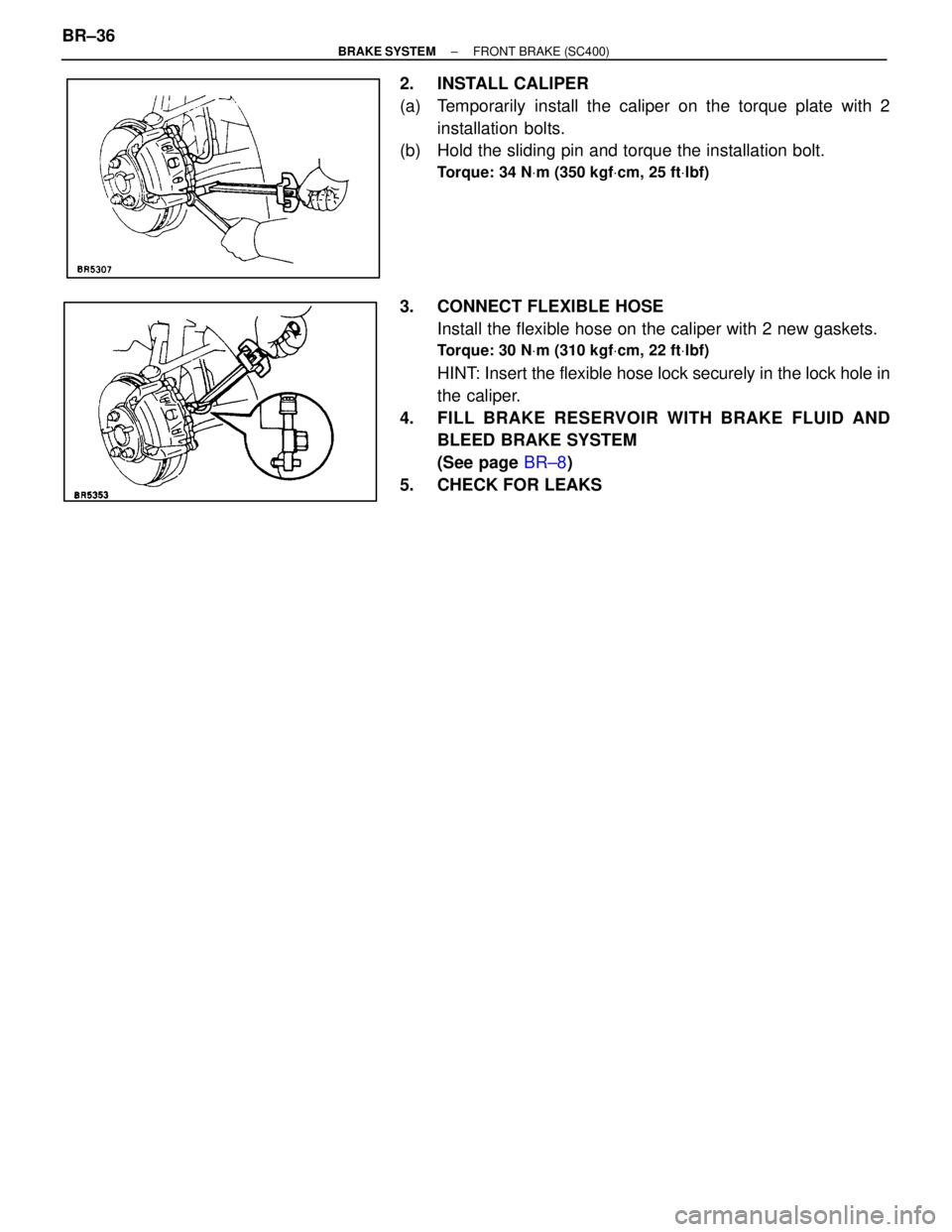
2. INSTALL CALIPER
(a) Temporarily install the caliper on the torque plate with 2installation bolts.
(b) Hold the sliding pin and torque the installation bolt.
Torque: 34 N Vm (350 kgf Vcm, 25 ft Vlbf)
3. CONNECT FLEXIBLE HOSE
Install the flexible hose on the caliper with 2 new gaskets.
Torque: 30 N Vm (310 kgf Vcm, 22 ft Vlbf)
HINT: Insert the flexible hose lock securely in the lock hole in
the caliper.
4. FILL BRAKE R ESERVOIR WITH BRAKE FLUID AND
BLEED BRAKE SYSTEM
(See page BR±8)
5. CHECK FOR LEAKS
BR±36
±
BRAKE SYSTEM FRONT BRAKE (SC400)
WhereEverybodyKnowsYourName
Page 1006 of 4087

REAR BRAKE
(Disc Brake)
COMPONENTS
BR047±06
REPLACEMENT OF BRAKE PADS
BR0PV±01
1. REMOVE REAR WHEELRemove the wheel and temporarily fasten the disc with the
hub nuts.
2. INSPECT PAD LINING THICKNESS Check the pad thickness through the caliper inspection hole
and replace pads if the thickness is not within the specifica-
tion.
Minimum thickness:
1.0 mm (0.039 in.)
±
BRAKE SYSTEM REAR BRAKE (Disc Brake)BR±37
WhereEverybodyKnowsYourName
Page 1007 of 4087

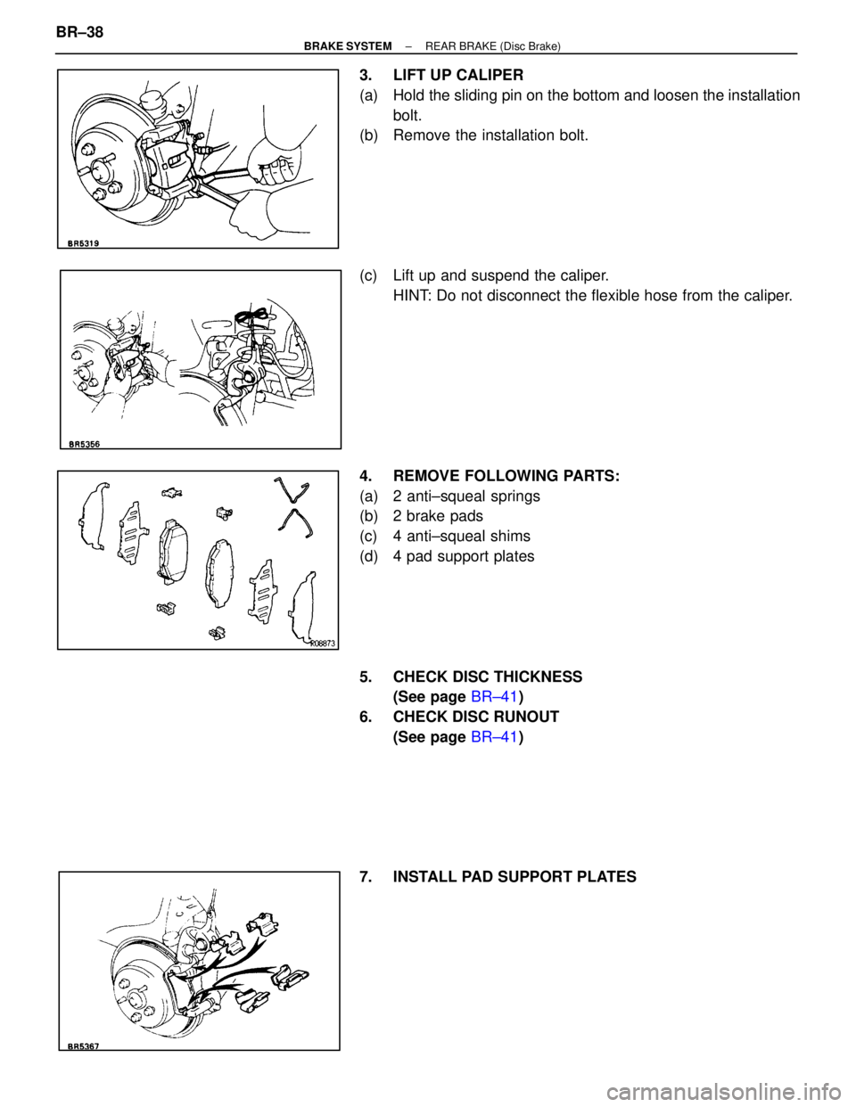
3. LIFT UP CALIPER
(a) Hold the sliding pin on the bottom and loosen the installationbolt.
(b) Remove the installation bolt.
(c) Lift up and suspend the caliper.
HINT: Do not disconnect the flexible hose from the caliper.
4. REMOVE FOLLOWING PARTS:
(a) 2 anti±squeal springs
(b) 2 brake pads
(c) 4 anti±squeal shims
(d) 4 pad support plates
5. CHECK DISC THICKNESS (See page BR±41)
6. CHECK DISC RUNOUT (See page BR±41)
7. INSTALL PAD SUPPORT PLATES
BR±38
±
BRAKE SYSTEM REAR BRAKE (Disc Brake)
WhereEverybodyKnowsYourName
Page 1008 of 4087

8. INSTALL NEW PADS
(a) Apply disc brake grease to both sides of the inner anti±squeal
shim.
(b) Install the 2 anti±squeal shims on each pad.
(c) Install the inner pad with the pad wear indicator plates facing
downward.
(d) Install the outer pad.
NOTICE: There should be no oil or grease adhering to the fric-
tion surfaces of the pads or the disc.
(e) Install the 2 anti±squeal springs.
9. INSTALL CALIPER
(a) Draw out a small amount of brake fluid from the reservoir.
(b) P re ss in th e pisto n with wa te r pu mp plie rs or simila r implement.
HINT: If the piston is difficult to push in, loosen the bleeder
plug and push in the piston while letting some brake fluid es-
cape.
(c) Install the caliper.
(d) Hold the sliding pin and torque the installation bolt.
Torque: 34 N Vm (350 kgf Vcm, 25 ft Vlbf)
10. INSTALL REAR WHEEL
11. CHECK THAT FLUID LEVEL IS AT MAX LINE
CALIPER REMOVAL
BR0EN±04
1. DISCONNECT FLEXIBLE HOSE
(a) Remove the union bolt and 2 gaskets from the caliper, then
disconnect the flexible hose from the caliper.
(b) Use a container to catch the brake fluid as it drains out.
2. REMOVE CALIPER
(a) Hold the sliding pin and loosen the 2 installation bolts.
(b) Remove the 2 installation bolts.
(c) Remove the caliper from the torque plate.
±
BRAKE SYSTEM REAR BRAKE (Disc Brake)BR±39
WhereEverybodyKnowsYourName
Page 1009 of 4087

3. REMOVE FOLLOWING PARTS:
(a) 2 anti±squeal springs
(b) 2 brake pads
CALIPER DISASSEMBLY
BR0EP±04
1. REMOVE CYLINDER BOOT SET RING AND CYLINDERBOOT
Using a screwdriver, remove the cylinder boot set ring and
cylinder boot from the caliper.
2. REMOVE PISTON
(a) Place a piece of cloth or similar article between the piston and
the caliper.
(b) Use compressed air to remove the piston from the caliper.
CAUTION: Do not place your fingers in front of the piston when
using compressed air.
3. REMOVE PISTON SEAL Using a screwdriver, remove the piston seal from the caliper.
4. REMOVE SLIDING PINS AND DUST BOOTS
(a) Remove the 2 sliding pins from the torque plate.
BR±40
±
BRAKE SYSTEM REAR BRAKE (Disc Brake)
WhereEverybodyKnowsYourName
Page 1010 of 4087

(b) Using a screwdriver and hammer, tap out the 2 dust boots.
REAR BRAKE COMPONENTS
INSPECTION AND REPAIR
BR04B±06
1. MEASURE PAD LINING THICKNESSUsing a ruler, measure the pad lining thickness.
Standard thickness:
10.0 mm (0.394 in.)
Minimum thickness: 1.0 mm (0.039 in.)
Replace the pad if the pad's thickness is at the minimum
thickness or less, or if the pad has severely uneven wear.
2. MEASURE DISC THICKNESS
Using a micrometer, measure the disc thickness.
Standard thickness:
16.0 mm (0.630 in.)
Minimum thickness:
15.0 mm (0.591 in.)
Replace the disc if the thickness of the disc is at the minimum
thickness or less. Replace the disc or grind it on a lathe if it
is scored or is worn unevenly.
3. MEASURE DISC RUNOUT
Measure the disc runout at 10 mm (0.39 in.) from the outer
edge of the disc.
Maximum disc runout:
0.05 mm (0.0020 in.)
If the disc's runout is at the maximum value or greater, check
the bearing play in the axial direction and check the axle hub
runout (See page SA±52). If the bearing play and axle hub
runout are not abnormal, adjust the disc runout.
4. IF NECESSARY, ADJUST DISC RUNOUT
(a) Remove the 2 bolt and torque plate from the carrier.
(b) Remove the hub nuts and the disc. Reinstall the disc 1/5 of
a turn round from its original position on the hub. Install and
torque the hub nuts.
Torque: 103 N Vm (1,050 kgf Vcm, 76 ft Vlbf)
Remeasure the disc runout. Make a note of the runout and
the disc's position on the hub.
±
BRAKE SYSTEM REAR BRAKE (Disc Brake)BR±41
WhereEverybodyKnowsYourName