LEXUS SC400 1991 Service Repair Manual
Manufacturer: LEXUS, Model Year: 1991, Model line: SC400, Model: LEXUS SC400 1991Pages: 4087, PDF Size: 75.75 MB
Page 1761 of 4087
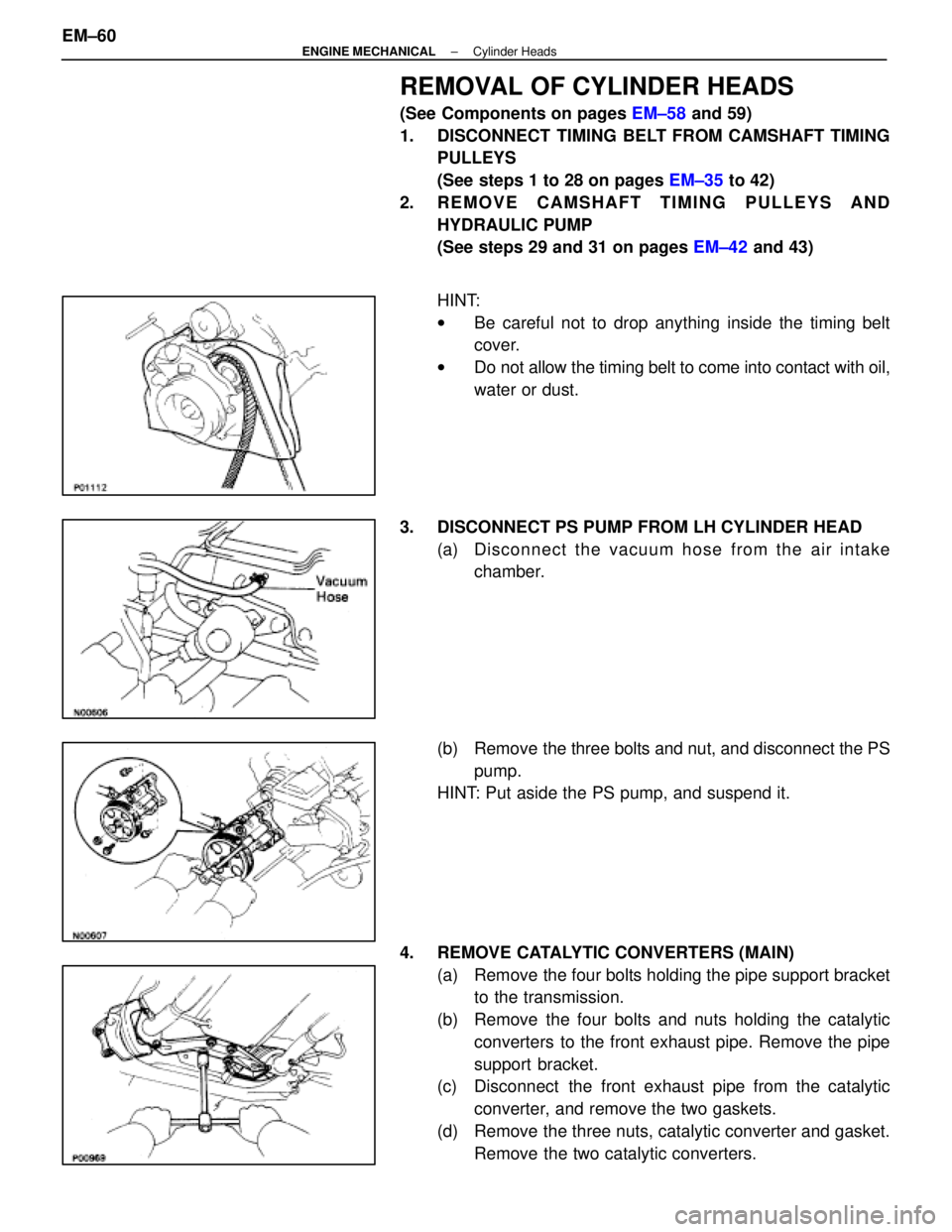
REMOVAL OF CYLINDER HEADS
(See Components on pages EM±58 and 59)
1. DISCONNECT TIMING BELT FROM CAMSHAFT TIMING PULLEYS
(See steps 1 to 28 on pages EM±35 to 42)
2. REMOVE CAMSHAFT TIMING PULLEYS AND HYDRAULIC PUMP
(See steps 29 and 31 on pages EM±42 and 43)
HINT:
w Be careful not to drop anything inside the timing belt
cover.
w Do not allow the timing belt to come into contact with oil,
water or dust.
3. DISCONNECT PS PUMP FROM LH CYLINDER HEAD (a) Disc onnect the vacuum hose from the air intake
chamber.
(b) Remove the three bolts and nut, and disconnect the PS pump.
HINT: Put aside the PS pump, and suspend it.
4. REMOVE CATALYTIC CONVERTERS (MAIN) (a) Remove the four bolts holding the pipe support bracketto the transmission.
(b) Remove the four bolts and nuts holding the catalytic converters to the front exhaust pipe. Remove the pipe
support bracket.
(c) Disconnect the front exhaust pipe from the catalytic
converter, and remove the two gaskets.
(d) Remove the three nuts, catalytic converter and gasket. Remove the two catalytic converters.
EM±60
±
ENGINE MECHANICAL Cylinder Heads
WhereEverybodyKnowsYourName
Page 1762 of 4087
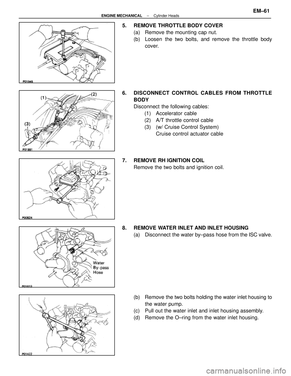
5. REMOVE THROTTLE BODY COVER(a) Remove the mounting cap nut.
(b) Loosen the two bolts, and remove the throttle bodycover.
6. DISCONNECT CONTROL CABLES FROM THROTTLE BODY
Disconnect the following cables:(1) Accelerator cable
(2) A/T throttle control cable
(3) (w/ Cruise Control System) Cruise control actuator cable
7. REMOVE RH IGNITION COIL Remove the two bolts and ignition coil.
8. REMOVE WATER INLET AND INLET HOUSING (a) Disconnect the water by±pass hose from the ISC valve.
(b) Remove the two bolts holding the water inlet housing to the water pump.
(c) Pull out the water inlet and inlet housing assembly.
(d) Remove the O±ring from the water inlet housing.
±
ENGINE MECHANICAL Cylinder HeadsEM±61
WhereEverybodyKnowsYourName
Page 1763 of 4087
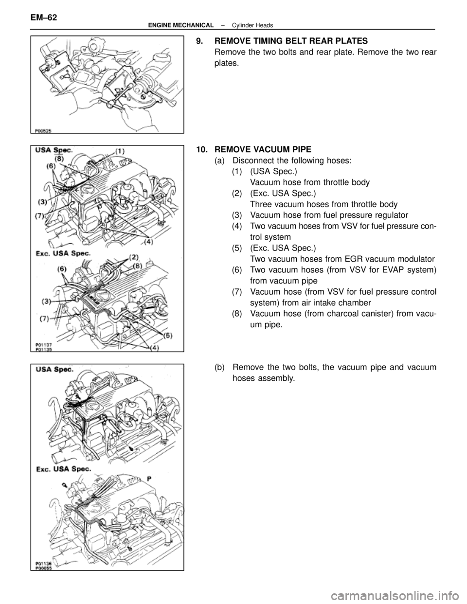
9. REMOVE TIMING BELT REAR PLATESRemove the two bolts and rear plate. Remove the two rear
plates.
10. REMOVE VACUUM PIPE (a) Disconnect the following hoses:(1) (USA Spec.)
Vacuum hose from throttle body
(2) (Exc. USA Spec.) Three vacuum hoses from throttle body
(3) Vacuum hose from fuel pressure regulator
(4) Two vacuum hoses from VSV for fuel pressure con-
trol system
(5) (Exc. USA Spec.) Two vacuum hoses from EGR vacuum modulator
(6) Two vacuum hoses (from VSV for EVAP system)
from vacuum pipe
(7) Vacuum hose (from VSV for fuel pressure control system) from air intake chamber
(8) Vacuum hose (from charcoal canister) from vacu-
um pipe.
(b) Remove the two bolts, the vacuum pipe and vacuum hoses assembly.
EM±62
±
ENGINE MECHANICAL Cylinder Heads
WhereEverybodyKnowsYourName
Page 1764 of 4087
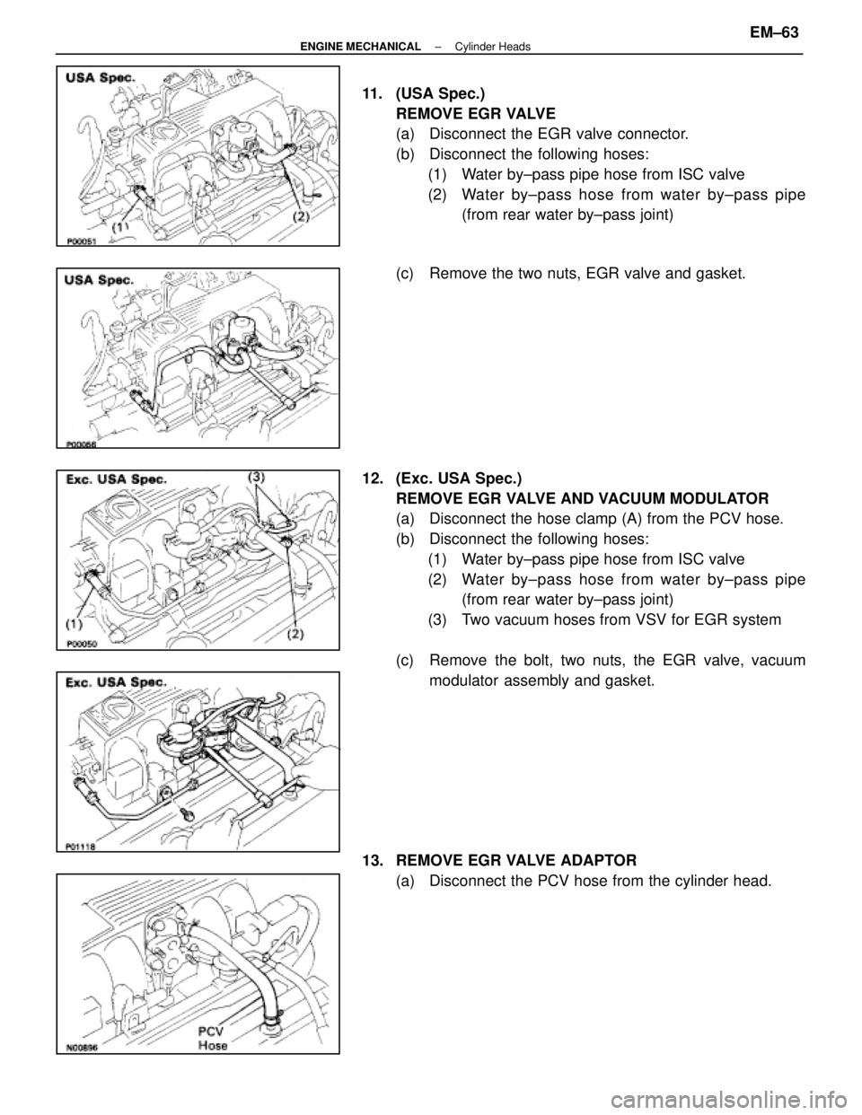
11. (USA Spec.)REMOVE EGR VALVE
(a) Disconnect the EGR valve connector.
(b) Disconnect the following hoses:(1) Water by±pass pipe hose from ISC valve
(2) Water by±pass hose from water by±pass pipe (from rear water by±pass joint)
(c) Remove the two nuts, EGR valve and gasket.
12. (Exc. USA Spec.) REMOVE EGR VALVE AND VACUUM MODULATOR
(a) Disconnect the hose clamp (A) from the PCV hose.
(b) Disconnect the following hoses:(1) Water by±pass pipe hose from ISC valve
(2) Water by±pass hose from water by±pass pipe (from rear water by±pass joint)
(3) Two vacuum hoses from VSV for EGR system
(c) Remove the bolt, two nuts, the EGR valve, vacuum modulator assembly and gasket.
13. REMOVE EGR VALVE ADAPTOR (a) Disconnect the PCV hose from the cylinder head.
±
ENGINE MECHANICAL Cylinder HeadsEM±63
WhereEverybodyKnowsYourName
Page 1765 of 4087

(b) Remove the two bolts, two nuts, adaptor and gasket.
(c) (USA Spec. only)Disconnect the EGR gas temperature sensor connec-
tor.
14. REMOVE ISC VALVE (a) Disconnect the ISC valve connector.
(b) Disconnect the water by±pass hose from the ISC valve.
(c) Remove the two nuts, ISC valve and gasket.
15. DISCONNECT HEATER WATER VALVE FROM BODY (a) Disconnect the VSV connector.
(b) Remove the bolt holding the engine wire clamp to thewater valve bracket.
(c) Remove the two bolts, and disconnect the water valve and bracket assembly.
16. REMOVE THROTTLE BODY (a) Disconnect the following connectors:(1) Throttle position sensor connector
(2) (w/ TRAC)
Sub±throttle position sensor connector
(3) (w/ TRAC) Sub±throttle actuator connector
EM±64
±
ENGINE MECHANICAL Cylinder Heads
WhereEverybodyKnowsYourName
Page 1766 of 4087
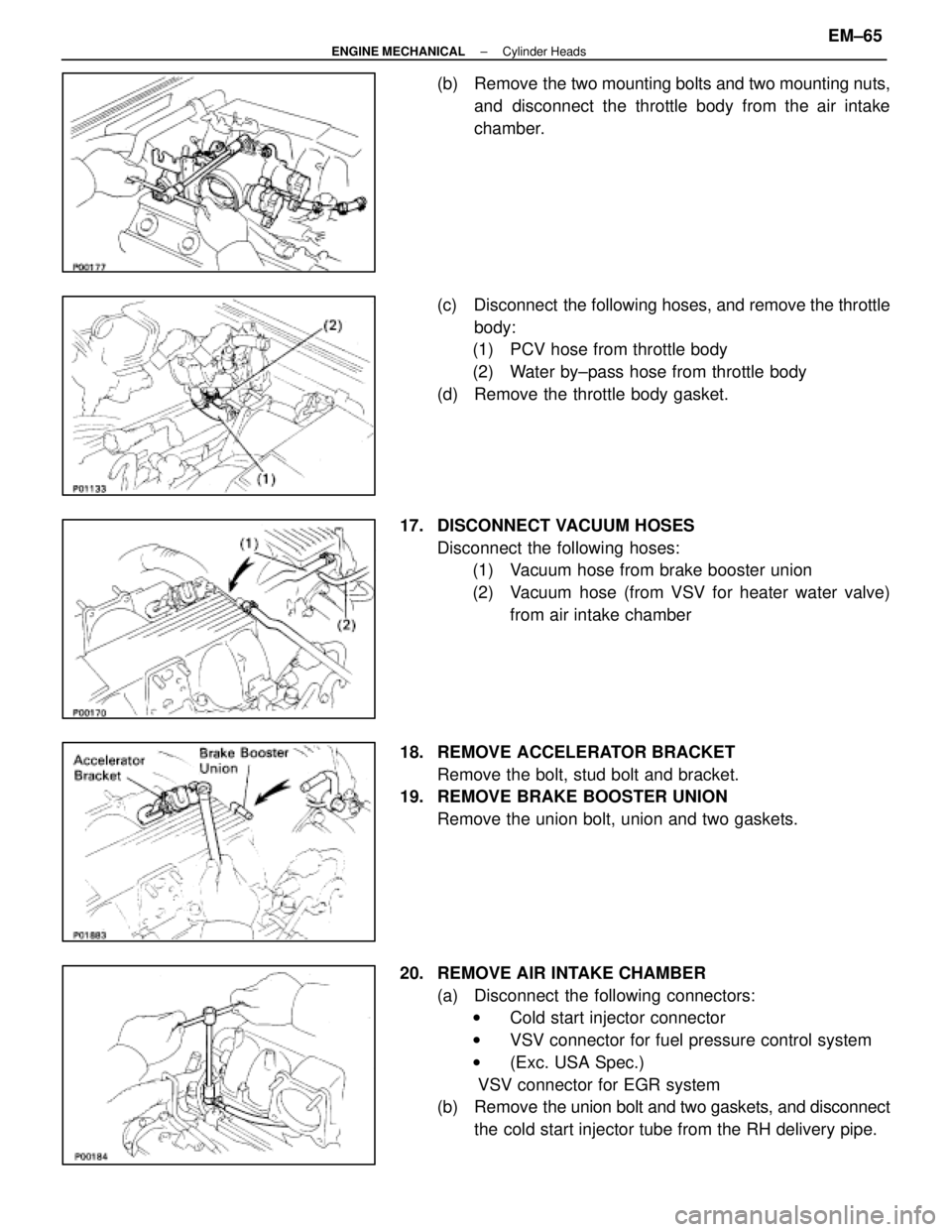
(b) Remove the two mounting bolts and two mounting nuts,and disconnect the throttle body from the air intake
chamber.
(c) Disconnect the following hoses, and remove the throttle body:
(1) PCV hose from throttle body
(2) Water by±pass hose from throttle body
(d) Remove the throttle body gasket.
17. DISCONNECT VACUUM HOSES Disconnect the following hoses:(1) Vacuum hose from brake booster union
(2) Vacuum hose (from VSV for heater water valve)
from air intake chamber
18. REMOVE ACCELERATOR BRACKET Remove the bolt, stud bolt and bracket.
19. REMOVE BRAKE BOOSTER UNION
Remove the union bolt, union and two gaskets.
20. REMOVE AIR INTAKE CHAMBER (a) Disconnect the following connectors:w Cold start injector connector
w VSV connector for fuel pressure control system
w (Exc. USA Spec.)
VSV connector for EGR system
(b) Remove the union bolt and two gaskets, and disconnect
the cold start injector tube from the RH delivery pipe.
±
ENGINE MECHANICAL Cylinder HeadsEM±65
WhereEverybodyKnowsYourName
Page 1767 of 4087
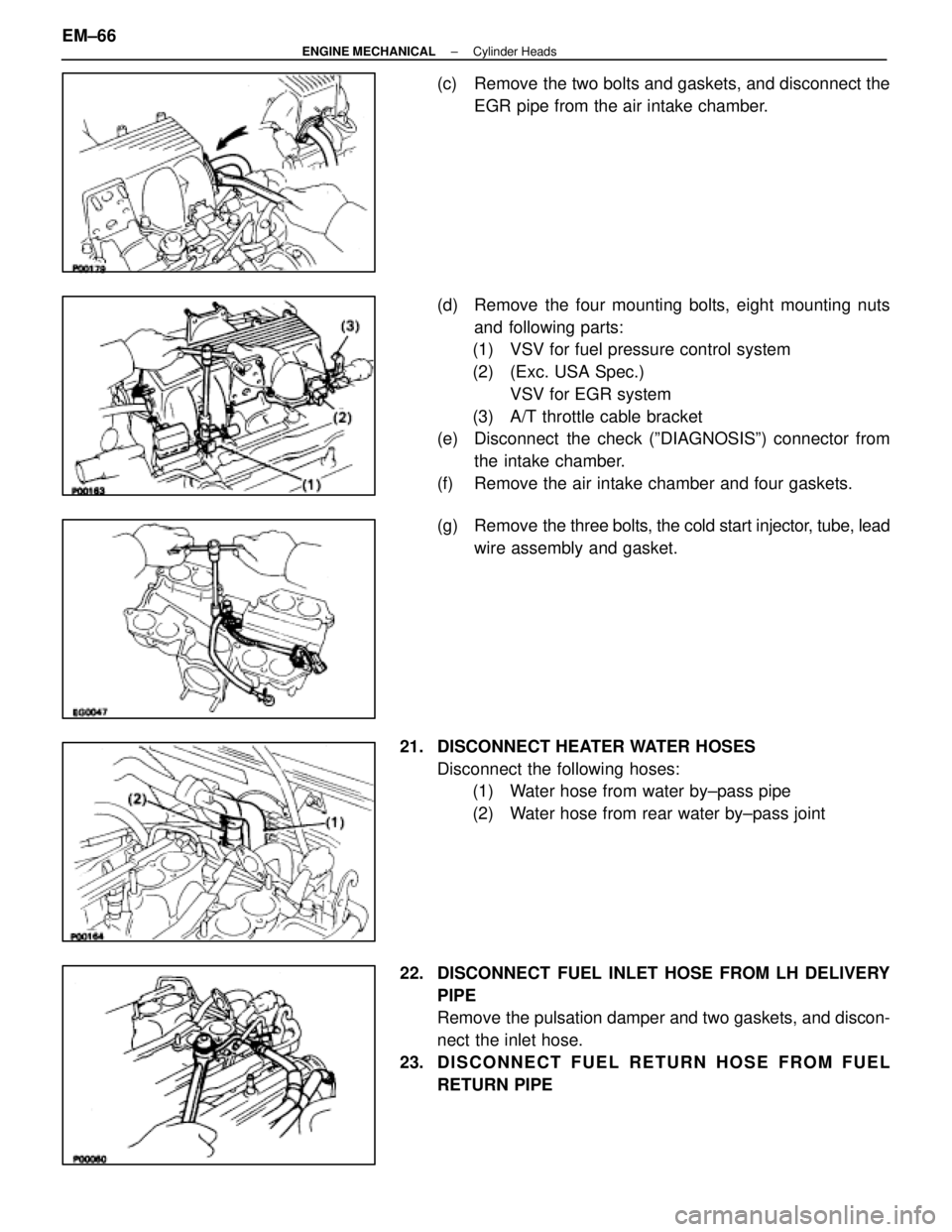
(c) Remove the two bolts and gaskets, and disconnect theEGR pipe from the air intake chamber.
(d) Remove the four mounting bolts, eight mounting nuts and following parts:
(1) VSV for fuel pressure control system
(2) (Exc. USA Spec.)
VSV for EGR system
(3) A/T throttle cable bracket
(e) Disconnect the check (ºDIAGNOSISº) connector from
the intake chamber.
(f) Remove the air intake chamber and four gaskets.
(g) Remove the three bolts, the cold start injector, tube, lead
wire assembly and gasket.
21. DISCONNECT HEATER WATER HOSES Disconnect the following hoses:(1) Water hose from water by±pass pipe
(2) Water hose from rear water by±pass joint
22. DISCONNECT FUEL INLET HOSE FROM LH DELIVERY PIPE
Remove the pulsation damper and two gaskets, and discon-
nect the inlet hose.
23. D I S C O N N E C T F U E L R E T U R N H O S E F R O M F U E L RETURN PIPE
EM±66
±
ENGINE MECHANICAL Cylinder Heads
WhereEverybodyKnowsYourName
Page 1768 of 4087
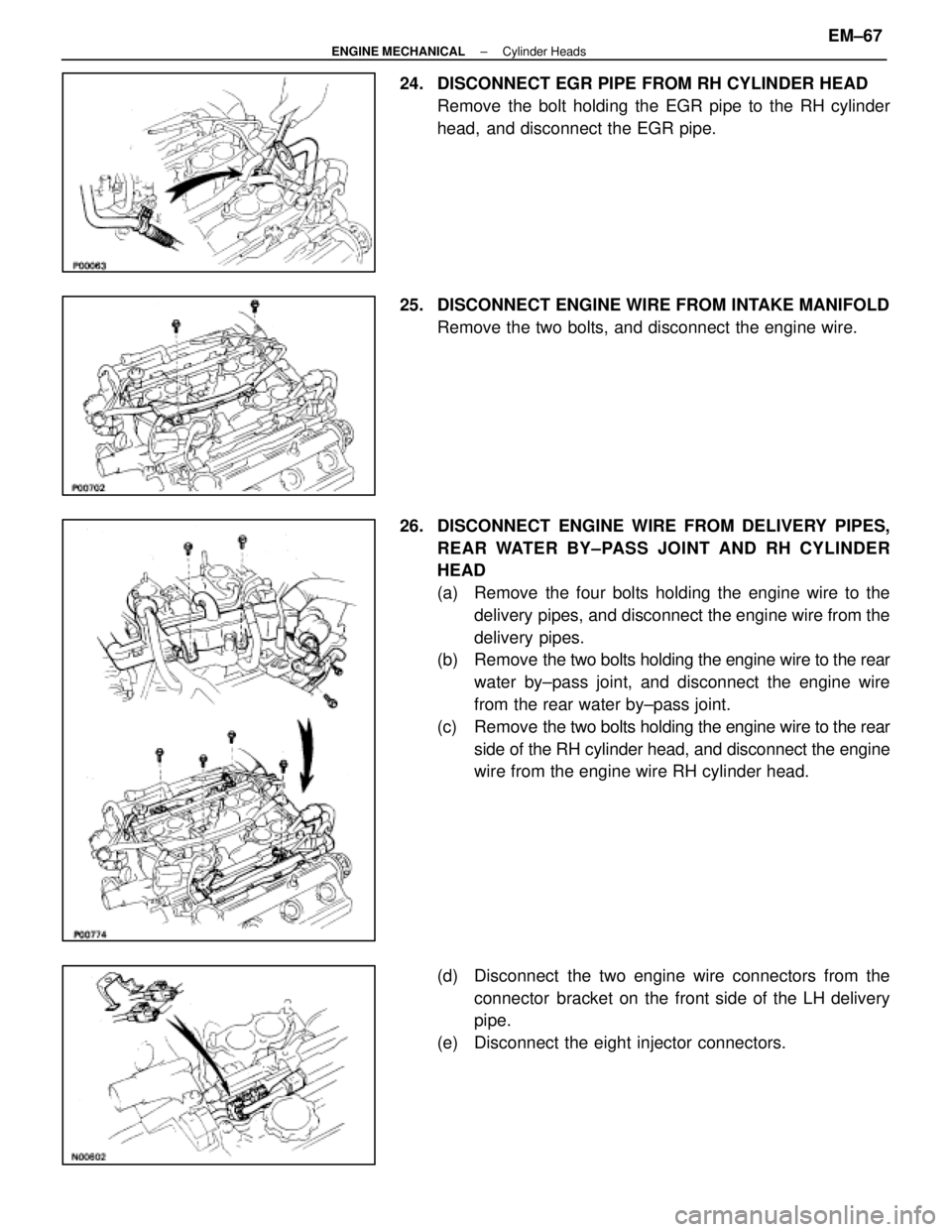
24. DISCONNECT EGR PIPE FROM RH CYLINDER HEADRemove the bolt holding the EGR pipe to the RH cylinder
head, and disconnect the EGR pipe.
25. DISCONNECT ENGINE WIRE FROM INTAKE MANIFOLD Remove the two bolts, and disconnect the engine wire.
26. DISCONNECT ENGINE WIRE FROM DELIVERY PIPES, REAR WATER BY±PASS JOINT AND RH CYLINDER
HEAD
(a) Remove the four bolts holding the engine wire to thedelivery pipes, and disconnect the engine wire from the
delivery pipes.
(b) Remove the two bolts holding the engine wire to the rear
water by±pass joint, and disconnect the engine wire
from the rear water by±pass joint.
(c) Remove the two bolts holding the engine wire to the rear
side of the RH cylinder head, and disconnect the engine
wire from the engine wire RH cylinder head.
(d) Disconnect the two engine wire connectors from the connector bracket on the front side of the LH delivery
pipe.
(e) Disconnect the eight injector connectors.
±
ENGINE MECHANICAL Cylinder HeadsEM±67
WhereEverybodyKnowsYourName
Page 1769 of 4087
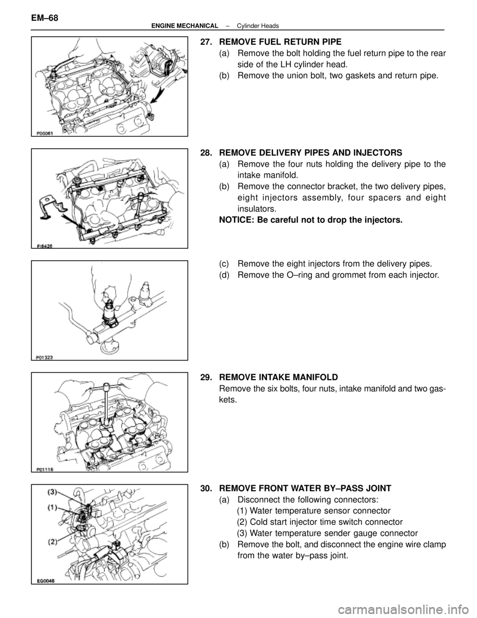
27. REMOVE FUEL RETURN PIPE(a) Remove the bolt holding the fuel return pipe to the rearside of the LH cylinder head.
(b) Remove the union bolt, two gaskets and return pipe.
28. REMOVE DELIVERY PIPES AND INJECTORS (a) Remove the four nuts holding the delivery pipe to theintake manifold.
(b) Remove the connector bracket, the two delivery pipes, eight injectors assembly, four spacers and eight
insulators.
NOTICE: Be careful not to drop the injectors.
(c) Remove the eight injectors from the delivery pipes.
(d) Remove the O±ring and grommet from each injector.
29. REMOVE INTAKE MANIFOLD Remove the six bolts, four nuts, intake manifold and two gas-
kets.
30. REMOVE FRONT WATER BY±PASS JOINT (a) Disconnect the following connectors:(1) Water temperature sensor connector
(2) Cold start injector time switch connector
(3) Water temperature sender gauge connector
(b) Remove the bolt, and disconnect the engine wire clamp from the water by±pass joint.
EM±68
±
ENGINE MECHANICAL Cylinder Heads
WhereEverybodyKnowsYourName
Page 1770 of 4087
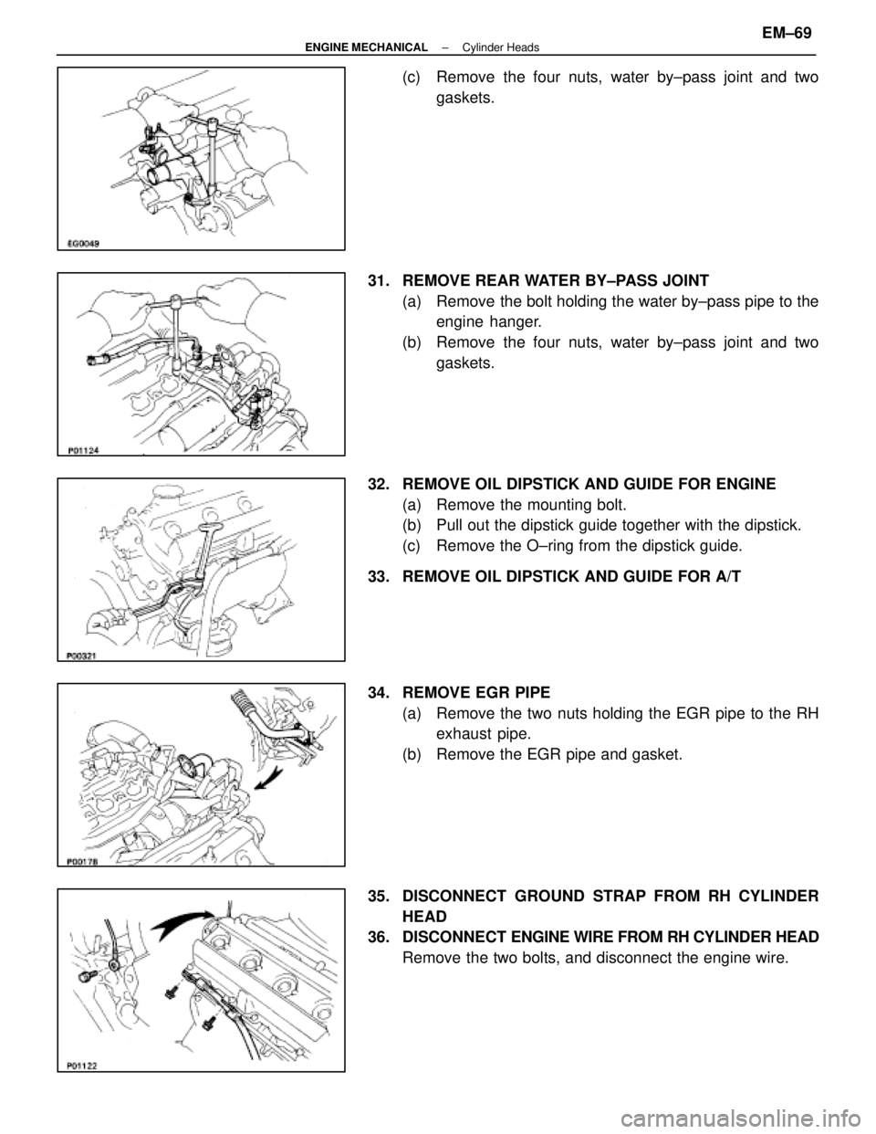
(c) Remove the four nuts, water by±pass joint and twogaskets.
31. REMOVE REAR WATER BY±PASS JOINT (a) Remove the bolt holding the water by±pass pipe to theengine hanger.
(b) Remove the four nuts, water by±pass joint and two gaskets.
32. REMOVE OIL DIPSTICK AND GUIDE FOR ENGINE (a) Remove the mounting bolt.
(b) Pull out the dipstick guide together with the dipstick.
(c) Remove the O±ring from the dipstick guide.
33. REMOVE OIL DIPSTICK AND GUIDE FOR A/T
34. REMOVE EGR PIPE (a) Remove the two nuts holding the EGR pipe to the RHexhaust pipe.
(b) Remove the EGR pipe and gasket.
35. DISCONNECT GROUND STRAP FROM RH CYLINDER HEAD
36. DISCONNECT ENGINE WIRE FROM RH CYLINDER HEAD
Remove the two bolts, and disconnect the engine wire.
±
ENGINE MECHANICAL Cylinder HeadsEM±69
WhereEverybodyKnowsYourName