LEXUS SC400 1991 Service Repair Manual
Manufacturer: LEXUS, Model Year: 1991, Model line: SC400, Model: LEXUS SC400 1991Pages: 4087, PDF Size: 75.75 MB
Page 1791 of 4087
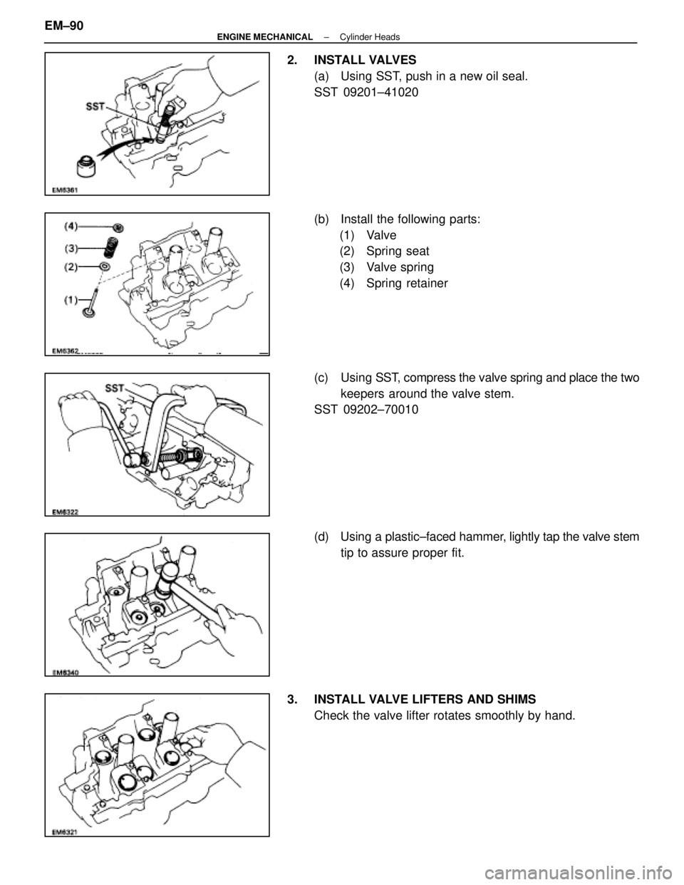
2. INSTALL VALVES(a) Using SST, push in a new oil seal.
SST 09201±41020
(b) Install the following parts:(1) Valve
(2) Spring seat
(3) Valve spring
(4) Spring retainer
(c) Using SST, compress the valve spring and place the two
keepers around the valve stem.
SST 09202±70010
(d) Using a plastic±faced hammer, lightly tap the valve stem
tip to assure proper fit.
3. INSTALL VALVE LIFTERS AND SHIMS Check the valve lifter rotates smoothly by hand.
EM±90
±
ENGINE MECHANICAL Cylinder Heads
WhereEverybodyKnowsYourName
Page 1792 of 4087
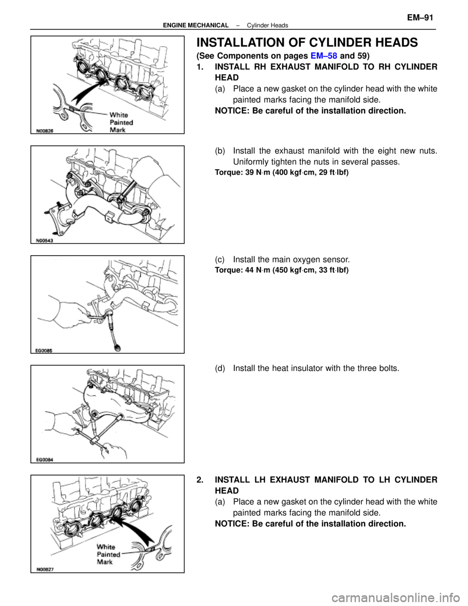
INSTALLATION OF CYLINDER HEADS
(See Components on pages EM±58 and 59)
1. INSTALL RH EXHAUST MANIFOLD TO RH CYLINDER HEAD
(a) Place a new gasket on the cylinder head with the white
painted marks facing the manifold side.
NOTICE: Be careful of the installation direction.
(b) Install the exhaust manifold with the eight new nuts. Uniformly tighten the nuts in several passes.
Torque: 39 N Vm (400 kgf Vcm, 29 ft Vlbf)
(c) Install the main oxygen sensor.
Torque: 44 N Vm (450 kgf Vcm, 33 ft Vlbf)
(d) Install the heat insulator with the three bolts.
2. INSTALL LH EXHAUST MANIFOLD TO LH CYLINDER HEAD
(a) Place a new gasket on the cylinder head with the whitepainted marks facing the manifold side.
NOTICE: Be careful of the installation direction.
±
ENGINE MECHANICAL Cylinder HeadsEM±91
WhereEverybodyKnowsYourName
Page 1793 of 4087
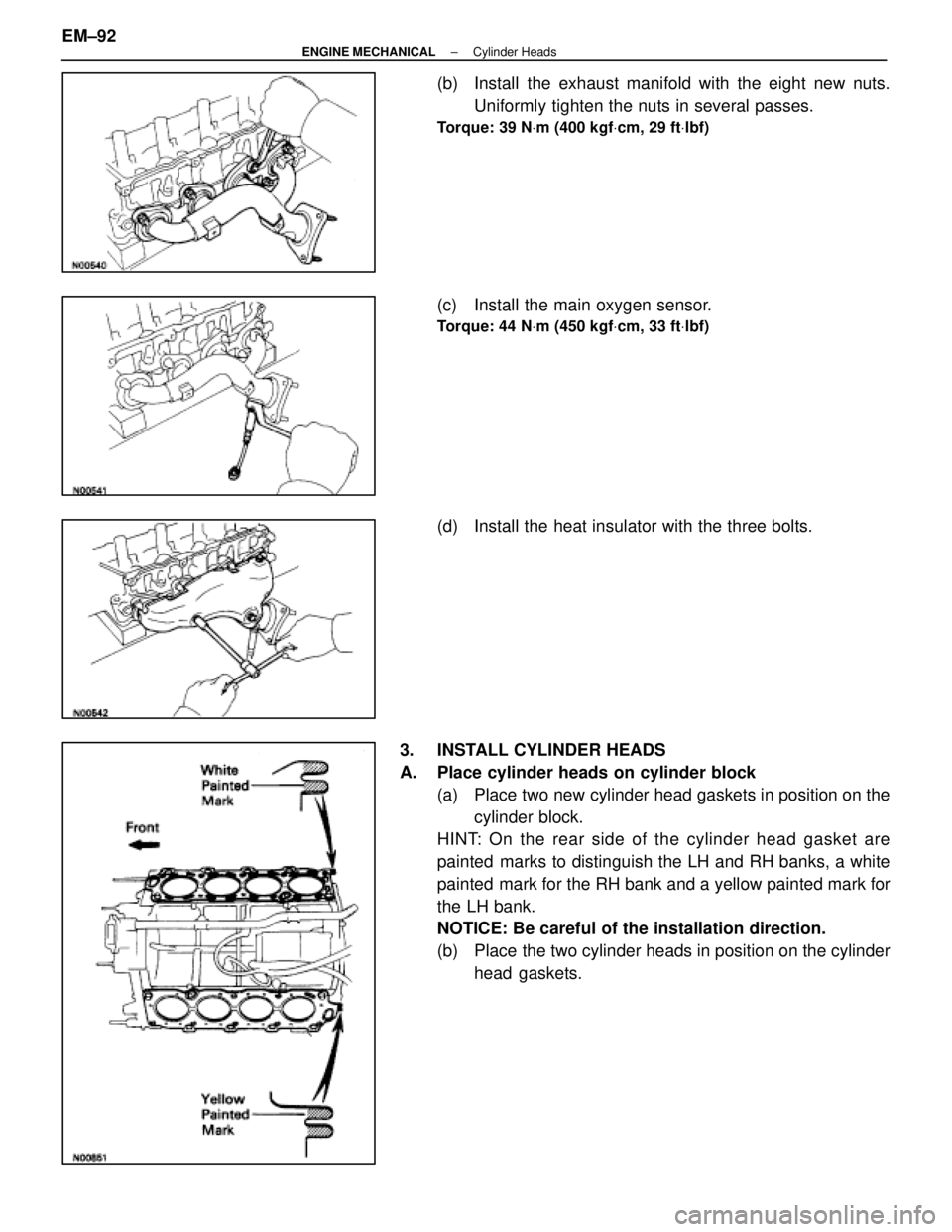
(b) Install the exhaust manifold with the eight new nuts.Uniformly tighten the nuts in several passes.
Torque: 39 N Vm (400 kgf Vcm, 29 ft Vlbf)
(c) Install the main oxygen sensor.
Torque: 44 N Vm (450 kgf Vcm, 33 ft Vlbf)
(d) Install the heat insulator with the three bolts.
3. INSTALL CYLINDER HEADS
A. Place cylinder heads on cylinder block (a) Place two new cylinder head gaskets in position on thecylinder block.
HINT: On the rear side of the cylinder head gasket are
painted marks to distinguish the LH and RH banks, a white
painted mark for the RH bank and a yellow painted mark for
the LH bank.
NOTICE: Be careful of the installation direction.
(b) Place the two cylinder heads in position on the cylinder
head gaskets.
EM±92
±
ENGINE MECHANICAL Cylinder Heads
WhereEverybodyKnowsYourName
Page 1794 of 4087
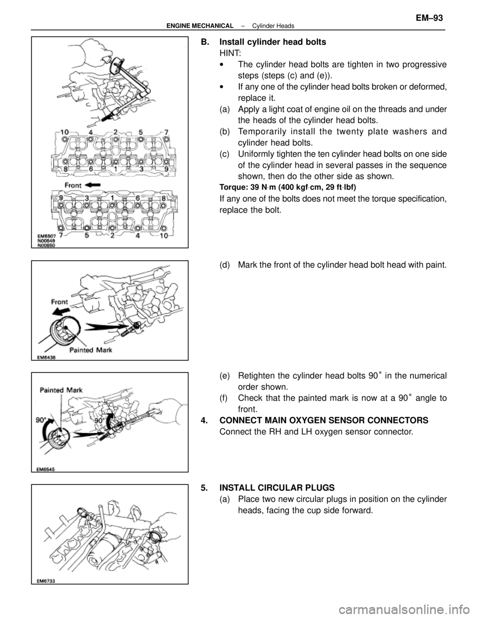
B. Install cylinder head boltsHINT:
wThe cylinder head bolts are tighten in two progressive
steps (steps (c) and (e)).
w If any one of the cylinder head bolts broken or deformed,
replace it.
(a) Apply a light coat of engine oil on the threads and under
the heads of the cylinder head bolts.
(b) Te mp o ra rily in sta ll th e twe n ty pla te wa sh e rs an d cylinder head bolts.
(c) Uniformly tighten the ten cylinder head bolts on one side
of the cylinder head in several passes in the sequence
shown, then do the other side as shown.
Torque: 39 N Vm (400 kgf Vcm, 29 ft Vlbf)
If any one of the bolts does not meet the torque specification,
replace the bolt.
(d) Mark the front of the cylinder head bolt head with paint.
(e) Retighten the cylinder head bolts 90 ° in the numerical
order shown.
(f) Check that the painted mark is now at a 90 ° angle to
front.
4. CONNECT MAIN OXYGEN SENSOR CONNECTORS Connect the RH and LH oxygen sensor connector.
5. INSTALL CIRCULAR PLUGS (a) Place two new circular plugs in position on the cylinderheads, facing the cup side forward.
±
ENGINE MECHANICAL Cylinder HeadsEM±93
WhereEverybodyKnowsYourName
Page 1795 of 4087
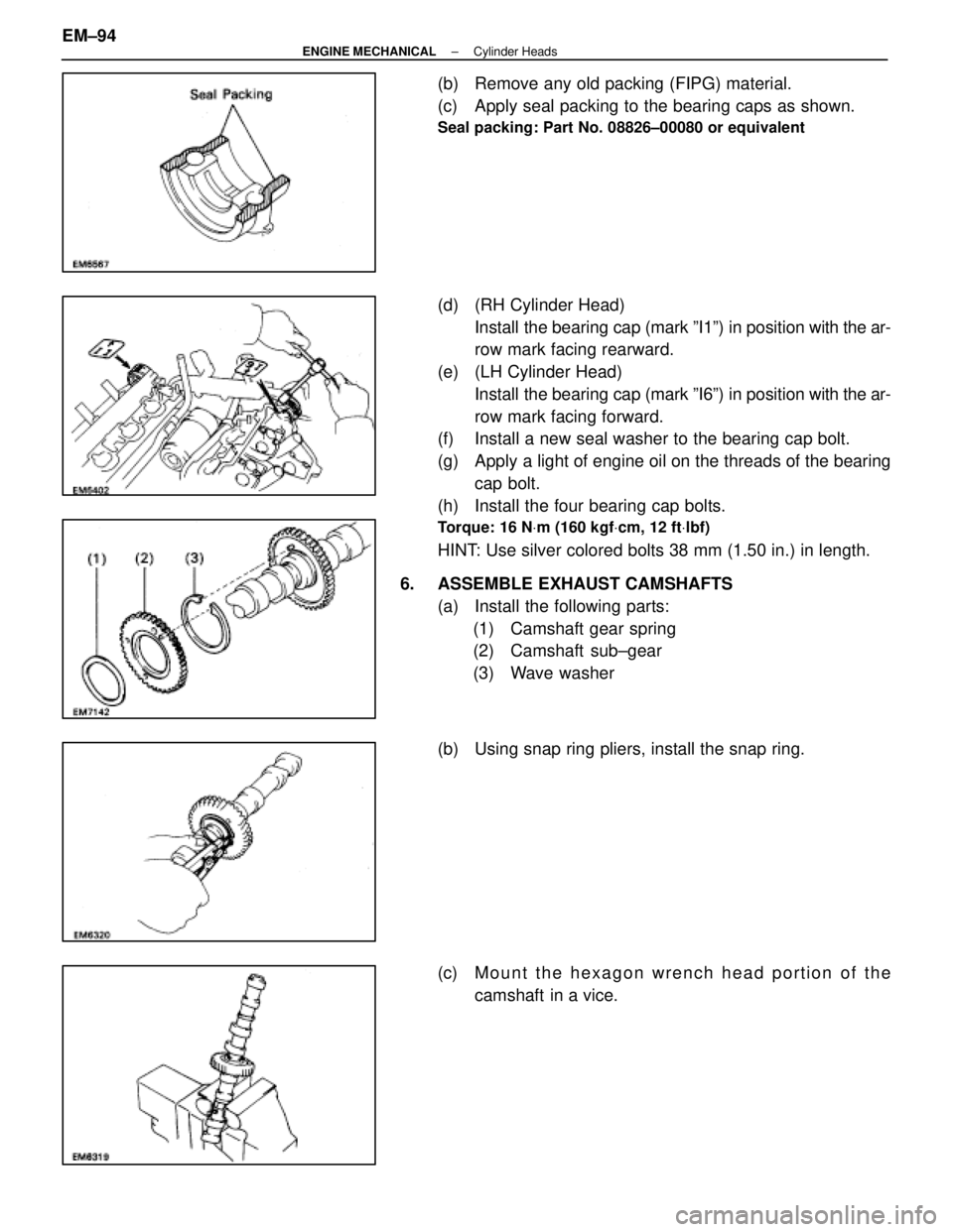
(b) Remove any old packing (FIPG) material.
(c) Apply seal packing to the bearing caps as shown.
Seal packing: Part No. 08826±00080 or equivalent
(d) (RH Cylinder Head)Install the bearing cap (mark ºI1º) in position with the ar-
row mark facing rearward.
(e) (LH Cylinder Head) Install the bearing cap (mark ºI6º) in position with the ar-
row mark facing forward.
(f) Install a new seal washer to the bearing cap bolt.
(g) Apply a light of engine oil on the threads of the bearing
cap bolt.
(h) Install the four bearing cap bolts.
Torque: 16 N Vm (160 kgf Vcm, 12 ft Vlbf)
HINT: Use silver colored bolts 38 mm (1.50 in.) in length.
6. ASSEMBLE EXHAUST CAMSHAFTS (a) Install the following parts:(1) Camshaft gear spring
(2) Camshaft sub±gear
(3) Wave washer
(b) Using snap ring pliers, install the snap ring.
(c) M ount the hexagon wrench head portion of the
camshaft in a vice.
EM±94
±
ENGINE MECHANICAL Cylinder Heads
WhereEverybodyKnowsYourName
Page 1796 of 4087
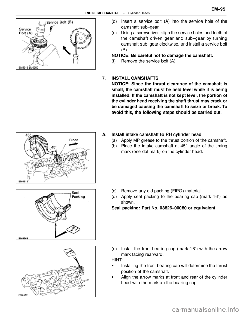
(d) Insert a service bolt (A) into the service hole of thecamshaft sub±gear.
(e) Using a screwdriver, align the service holes and teeth of the camshaft driven gear and sub±gear by turning
camshaft sub±gear clockwise, and install a service bolt
(B).
NOTICE: Be careful not to damage the camshaft.
(f) Remove the service bolt (A).
7. INSTALL CAMSHAFTS NOTICE: Since the thrust clearance of the camshaft is
small, the camshaft must be held level while it is being
installed. If the camshaft is not kept level, the portion of
the cylinder head receiving the shaft thrust may crack or
be damaged causing the camshaft to seize or break. To
avoid this, the following steps should be carried out.
A. Install intake camshaft to RH cylinder head (a) Apply MP grease to the thrust portion of the camshaft.
(b) Place the intake camshaft at 45 ° angle of the timing
mark (one dot mark) on the cylinder head.
(c) Remove any old packing (FIPG) material.
(d) Apply seal packing to the bearing cap (mark ºI6º) as shown.
Seal packing: Part No. 08826±00080 or equivalent
(e) Install the front bearing cap (mark ºI6º) with the arrow mark facing rearward.
HINT:
w Installing the front bearing cap will determine the thrust
position of the camshaft.
w Align the arrow marks at front and rear of the cylinder
head with the mark on the bearing cap.
±
ENGINE MECHANICAL Cylinder HeadsEM±95
WhereEverybodyKnowsYourName
Page 1797 of 4087
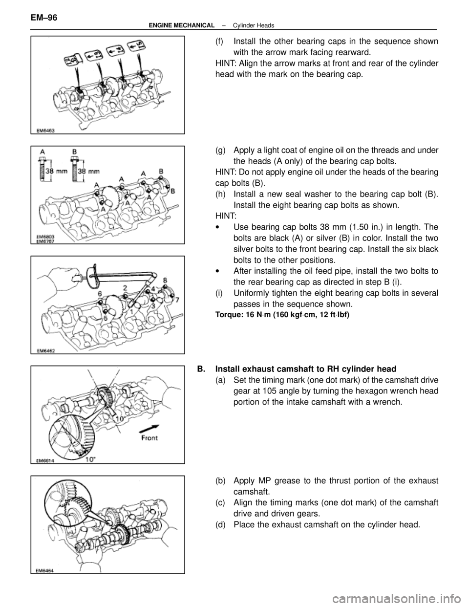
(f) Install the other bearing caps in the sequence shownwith the arrow mark facing rearward.
HINT: Align the arrow marks at front and rear of the cylinder
head with the mark on the bearing cap.
(g) Apply a light coat of engine oil on the threads and under
the heads (A only) of the bearing cap bolts.
HINT: Do not apply engine oil under the heads of the bearing
cap bolts (B).
(h) Install a new seal washer to the bearing cap bolt (B).
Install the eight bearing cap bolts as shown.
HINT:
w Use bearing cap bolts 38 mm (1.50 in.) in length. The
bolts are black (A) or silver (B) in color. Install the two
silver bolts to the front bearing cap. Install the six black
bolts to the other positions.
w After installing the oil feed pipe, install the two bolts to
the rear bearing cap as directed in step B (i).
(i) Uniformly tighten the eight bearing cap bolts in several passes in the sequence shown.
Torque: 16 N Vm (160 kgf Vcm, 12 ft Vlbf)
B. Install exhaust camshaft to RH cylinder head
(a) Set the timing mark ( one dot mark) of the camshaft drive
gear at 105 angle by turning the hexagon wrench head
portion of the intake camshaft with a wrench.
(b) Apply MP grease to the thrust portion of the exhaust camshaft.
(c) Align the timing marks (one dot mark) of the camshaft
drive and driven gears.
(d) Place the exhaust camshaft on the cylinder head.
EM±96
±
ENGINE MECHANICAL Cylinder Heads
WhereEverybodyKnowsYourName
Page 1798 of 4087
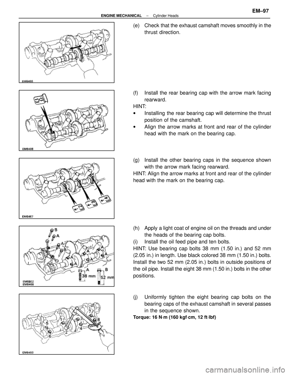
(e) Check that the exhaust camshaft moves smoothly in the
thrust direction.
(f) Install the rear bearing cap with the arrow mark facing rearward.
HINT:
w Installing the rear bearing cap will determine the thrust
position of the camshaft.
w Align the arrow marks at front and rear of the cylinder
head with the mark on the bearing cap.
(g) Install the other bearing caps in the sequence shown with the arrow mark facing rearward.
HINT: Align the arrow marks at front and rear of the cylinder
head with the mark on the bearing cap.
(h) Apply a light coat of engine oil on the threads and under
the heads of the bearing cap bolts.
(i) Install the oil feed pipe and ten bolts.
HINT: Use bearing cap bolts 38 mm (1.50 in.) and 52 mm
(2.05 in.) in length. Use black colored 38 mm (1.50 in.) bolts.
Install the two 52 mm (2.05 in.) bolts in outside positions of
the oil pipe. Install the eight 38 mm (1.50 in.) bolts in the other
positions.
(j) Uniformly tighten the eight bearing cap bolts on the bearing caps of the exhaust camshaft in several passes
in the sequence shown.
Torque: 16 N Vm (160 kgf Vcm, 12 ft Vlbf)
±
ENGINE MECHANICAL Cylinder HeadsEM±97
WhereEverybodyKnowsYourName
Page 1799 of 4087
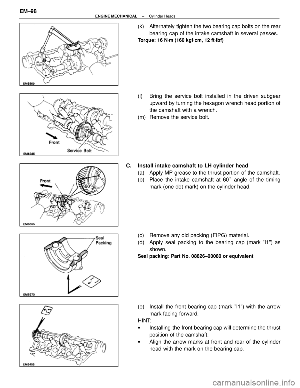
(k) Alternately tighten the two bearing cap bolts on the rearbearing cap of the intake camshaft in several passes.
Torque: 16 N Vm (160 kgf Vcm, 12 ft Vlbf)
(l) Bring the service bolt installed in the driven subgear
upward by turning the hexagon wrench head portion of
the camshaft with a wrench.
(m) Remove the service bolt.
C. Install intake camshaft to LH cylinder head (a) Apply MP grease to the thrust portion of the camshaft.
(b) Place the intake camshaft at 60 ° angle of the timing
mark (one dot mark) on the cylinder head.
(c) Remove any old packing (FIPG) material.
(d) Apply seal packing to the bearing cap (mark ºI1º) as shown.
Seal packing: Part No. 08826±00080 or equivalent
(e) Install the front bearing cap (mark ºI1º) with the arrow
mark facing forward.
HINT:
w Installing the front bearing cap will determine the thrust
position of the camshaft.
w Align the arrow marks at front and rear of the cylinder
head with the mark on the bearing cap.
EM±98
±
ENGINE MECHANICAL Cylinder Heads
WhereEverybodyKnowsYourName
Page 1800 of 4087
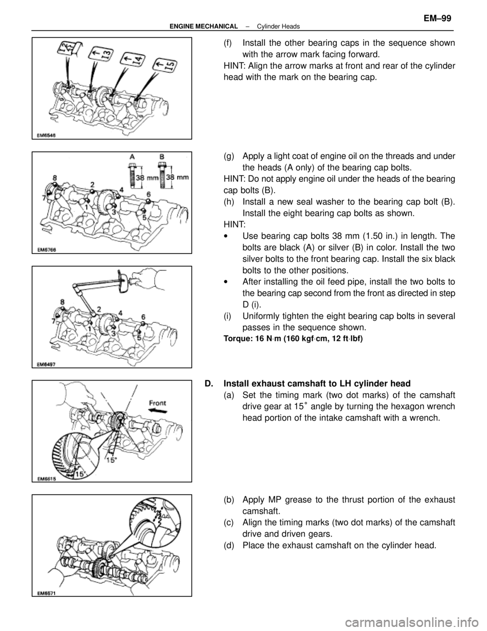
(f) Install the other bearing caps in the sequence shownwith the arrow mark facing forward.
HINT: Align the arrow marks at front and rear of the cylinder
head with the mark on the bearing cap.
(g) Apply a light coat of engine oil on the threads and under
the heads (A only) of the bearing cap bolts.
HINT: Do not apply engine oil under the heads of the bearing
cap bolts (B).
(h) Install a new seal washer to the bearing cap bolt (B).
Install the eight bearing cap bolts as shown.
HINT:
w Use bearing cap bolts 38 mm (1.50 in.) in length. The
bolts are black (A) or silver (B) in color. Install the two
silver bolts to the front bearing cap. Install the six black
bolts to the other positions.
w After installing the oil feed pipe, install the two bolts to
the bearing cap second from the front as directed in step
D (i).
(i) Uniformly tighten the eight bearing cap bolts in several passes in the sequence shown.
Torque: 16 N Vm (160 kgf Vcm, 12 ft Vlbf)
D. Install exhaust camshaft to LH cylinder head
(a) Set the timing mark (two dot marks) of the camshaftdrive gear at 15 ° angle by turning the hexagon wrench
head portion of the intake camshaft with a wrench.
(b) Apply MP grease to the thrust portion of the exhaust camshaft.
(c) Align the timing marks (two dot marks) of the camshaft
drive and driven gears.
(d) Place the exhaust camshaft on the cylinder head.
±
ENGINE MECHANICAL Cylinder HeadsEM±99
WhereEverybodyKnowsYourName