LEXUS SC400 1991 Service Repair Manual
Manufacturer: LEXUS, Model Year: 1991,
Model line: SC400,
Model: LEXUS SC400 1991
Pages: 4087, PDF Size: 75.75 MB
LEXUS SC400 1991 Service Repair Manual
SC400 1991
LEXUS
LEXUS
https://www.carmanualsonline.info/img/36/57051/w960_57051-0.png
LEXUS SC400 1991 Service Repair Manual
Trending: change time, wiring, trailer, width, oil filter, engine coolant, wire pin out
Page 1821 of 4087
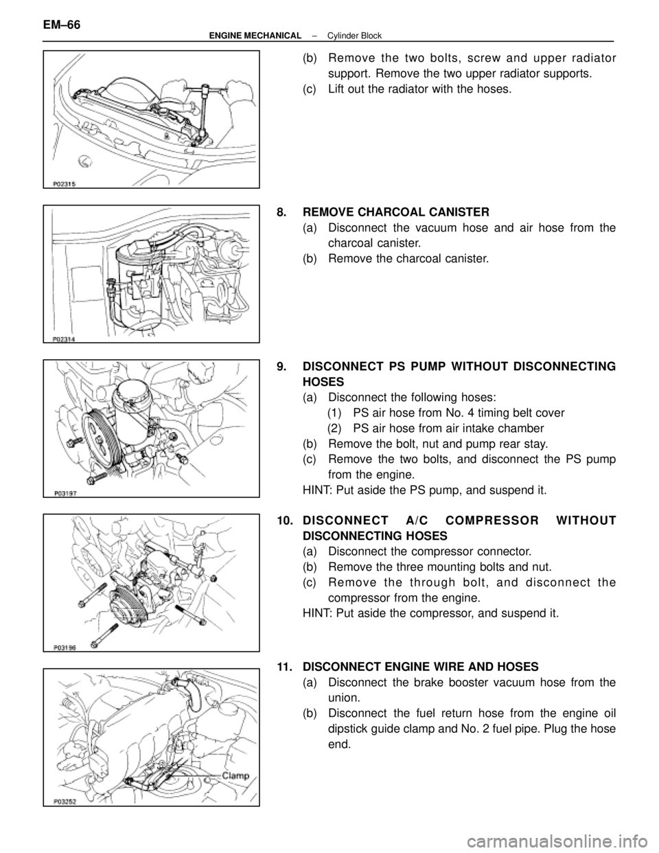
(b) Remove the two bolts, screw and upper radiatorsupport. Remove the two upper radiator supports.
(c) Lift out the radiator with the hoses.
8. REMOVE CHARCOAL CANISTER (a) Disconnect the vacuum hose and air hose from thecharcoal canister.
(b) Remove the charcoal canister.
9. DISCONNECT PS PUMP WITHOUT DISCONNECTING HOSES
(a) Disconnect the following hoses:(1) PS air hose from No. 4 timing belt cover
(2) PS air hose from air intake chamber
(b) Remove the bolt, nut and pump rear stay.
(c) Remove the two bolts, and disconnect the PS pump from the engine.
HINT: Put aside the PS pump, and suspend it.
10. D I S C O N N E C T A / C C O M P R ESSOR WITHOUT
DISCONNECTING HOSES
(a) Disconnect the compressor connector.
(b) Remove the three mounting bolts and nut.
(c) R e m o v e t h e t h r ough bolt, and disconnect the
compressor from the engine.
HINT: Put aside the compressor, and suspend it.
11. DISCONNECT ENGINE WIRE AND HOSES (a) Disconnect the brake booster vacuum hose from theunion.
(b) Disconnect the fuel return hose from the engine oil dipstick guide clamp and No. 2 fuel pipe. Plug the hose
end.
EM±66
±
ENGINE MECHANICAL Cylinder Block
WhereEverybodyKnowsYourName
Page 1822 of 4087
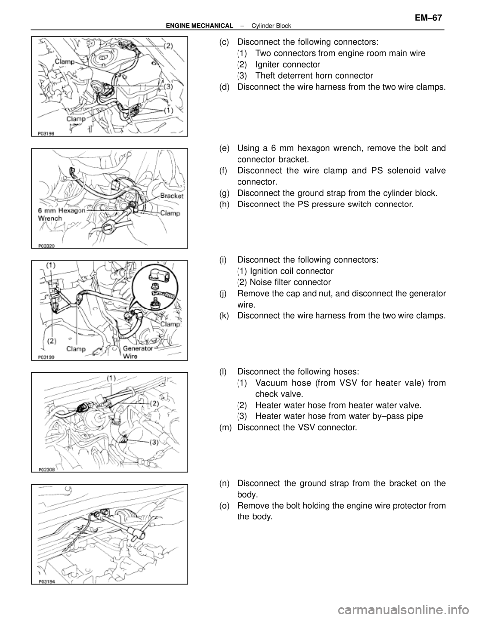
(c) Disconnect the following connectors:(1) Two connectors from engine room main wire
(2) Igniter connector
(3) Theft deterrent horn connector
(d) Disconnect the wire harness from the two wire clamps.
(e) Using a 6 mm hexagon wrench, remove the bolt and connector bracket.
(f) Disc onnect the wire clamp and PS solenoid valve
connector.
(g) Disconnect the ground strap from the cylinder block.
(h) Disconnect the PS pressure switch connector.
(i) Disconnect the following connectors: (1) Ignition coil connector
(2) Noise filter connector
(j) Remove the cap and nut, and disconnect the generator wire.
(k) Disconnect the wire harness from the two wire clamps.
(l) Disconnect the following hoses: (1) Vacuum hose (from VSV for heater vale) from check valve.
(2) Heater water hose from heater water valve.
(3) Heater water hose from water by±pass pipe
(m) Disconnect the VSV connector.
(n) Disconnect the ground strap from the bracket on the body.
(o) Remove the bolt holding the engine wire protector from
the body.
±
ENGINE MECHANICAL Cylinder BlockEM±67
WhereEverybodyKnowsYourName
Page 1823 of 4087
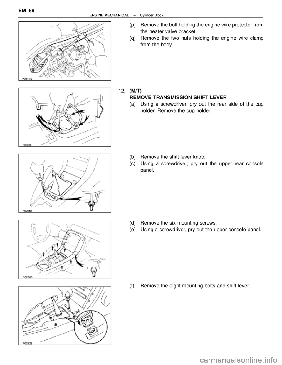
(p) Remove the bolt holding the engine wire protector fromthe heater valve bracket.
(q) Remove the two nuts holding the engine wire clamp from the body.
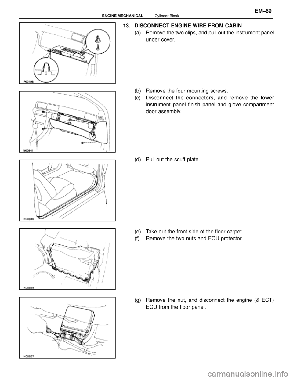
12. (M/T) REMOVE TRANSMISSION SHIFT LEVER
(a) Using a screwdriver, pry out the rear side of the cupholder. Remove the cup holder.
(b) Remove the shift lever knob.
(c) Using a screwdriver, pry out the upper rear console panel.
(d) Remove the six mounting screws.
(e) Using a screwdriver, pry out the upper console panel.
(f) Remove the eight mounting bolts and shift lever.
EM±68
±
ENGINE MECHANICAL Cylinder Block
WhereEverybodyKnowsYourName
Page 1824 of 4087
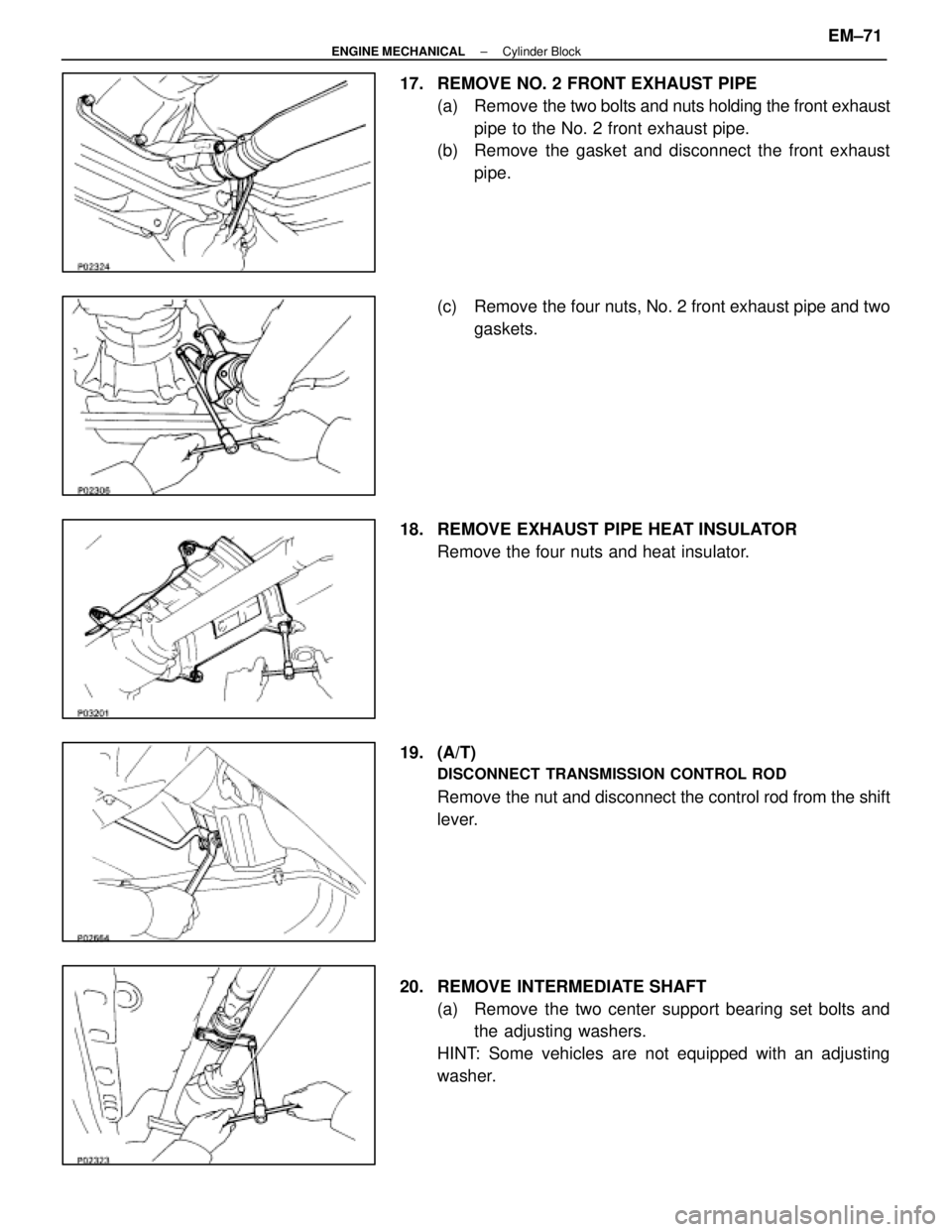
13. DISCONNECT ENGINE WIRE FROM CABIN(a) Remove the two clips, and pull out the instrument panelunder cover.
(b) Remove the four mounting screws.
(c) Disc onnect the connectors, and remove the lower
instrument panel finish panel and glove compartment
door assembly.
(d) Pull out the scuff plate.
(e) Take out the front side of the floor carpet.
(f) Remove the two nuts and ECU protector.
(g) Remove the nut, and disconnect the engine (& ECT) ECU from the floor panel.
±
ENGINE MECHANICAL Cylinder BlockEM±69
WhereEverybodyKnowsYourName
Page 1825 of 4087
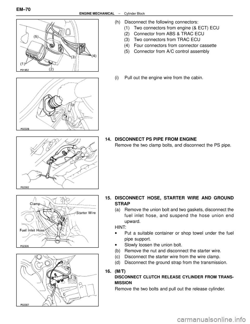
(h) Disconnect the following connectors:(1) Two connectors from engine (& ECT) ECU
(2) Connector from ABS & TRAC ECU
(3) Two connectors from TRAC ECU
(4) Four connectors from connector cassette
(5) Connector from A/C control assembly
(i) Pull out the engine wire from the cabin.
14. DISCONNECT PS PIPE FROM ENGINE Remove the two clamp bolts, and disconnect the PS pipe.
15. DISCONNECT HOSE, STARTER WIRE AND GROUND STRAP
(a) Remove the union bolt and two gaskets, disconnect thefuel inlet hose, and suspend the hose union end
upward.
HINT:
w Put a suitable container or shop towel under the fuel
pipe support.
w Slowly loosen the union bolt.
(b) Remove the nut and disconnect the starter wire.
(c) Disconnect the starter wire from the wire clamp.
(d) Disconnect the ground strap from the transmission.
16. (M/T)
DISCONNECT CLUTCH RELEASE CYLINDER FROM TRANS-
MISSION
Remove the two bolts and pull out the release cylinder.
EM±70
±
ENGINE MECHANICAL Cylinder Block
WhereEverybodyKnowsYourName
Page 1826 of 4087
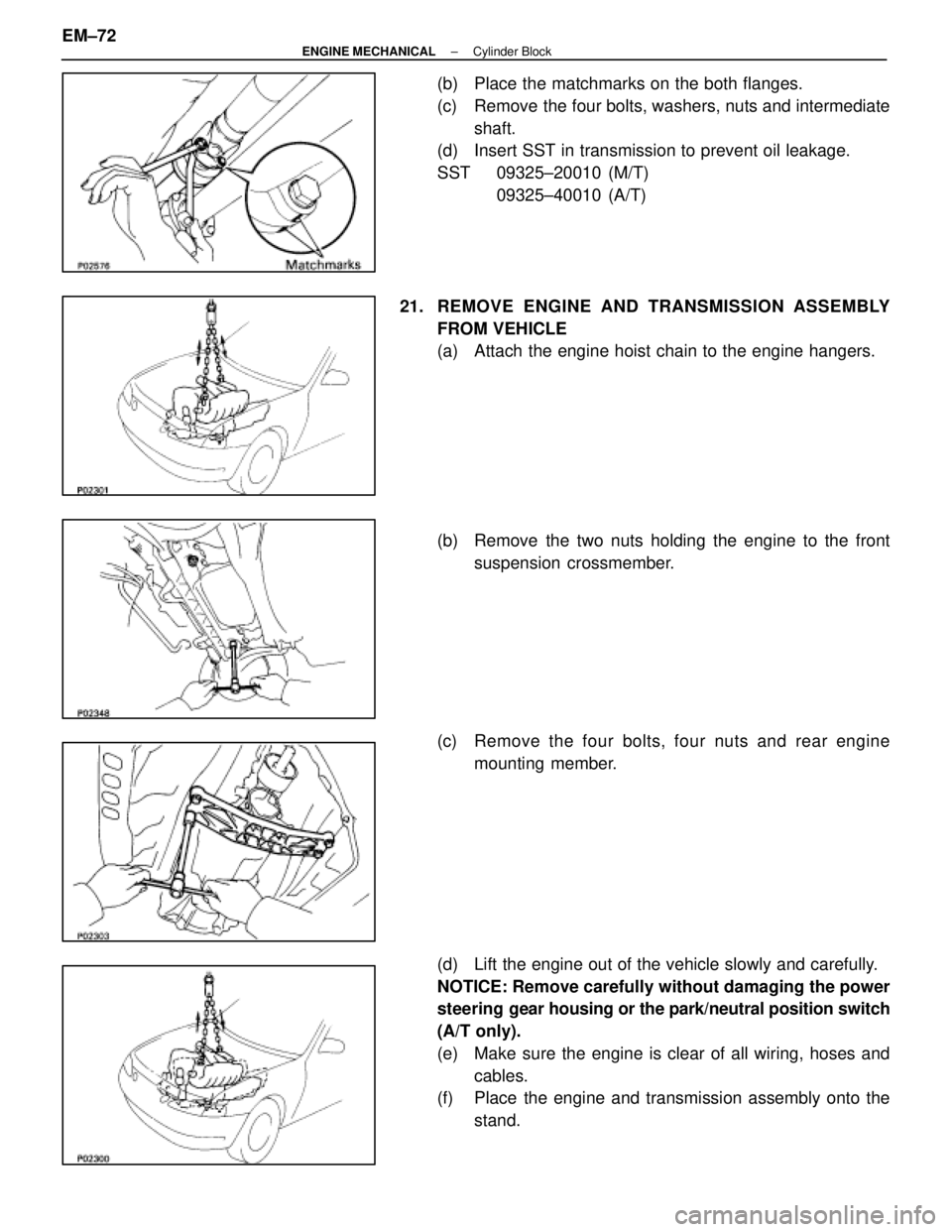
17. REMOVE NO. 2 FRONT EXHAUST PIPE(a) Remove the two bolts and nuts holding the front exhaust
pipe to the No. 2 front exhaust pipe.
(b) Remove the gasket and disconnect the front exhaust
pipe.
(c) Remove the four nuts, No. 2 front exhaust pipe and two gaskets.
18. REMOVE EXHAUST PIPE HEAT INSULATOR Remove the four nuts and heat insulator.
19. (A/T)
DISCONNECT TRANSMISSION CONTROL ROD
Remove the nut and disconnect the control rod from the shift
lever.
20. REMOVE INTERMEDIATE SHAFT (a) Remove the two center support bearing set bolts andthe adjusting washers.
HINT: Some vehicles are not equipped with an adjusting
washer.
±
ENGINE MECHANICAL Cylinder BlockEM±71
WhereEverybodyKnowsYourName
Page 1827 of 4087
(b) Place the matchmarks on the both flanges.
(c) Remove the four bolts, washers, nuts and intermediateshaft.
(d) Insert SST in transmission to prevent oil leakage.
SST 09325±20010 (M/T)
09325±40010 (A/T)
21. REMOVE ENGINE AND T RANSMISSION ASSEMBLY
FROM VEHICLE
(a) Attach the engine hoist chain to the engine hangers.
(b) Remove the two nuts holding the engine to the front suspension crossmember.
(c) Remove the four bolts, four nuts and rear engine mounting member.
(d) Lift the engine out of the vehicle slowly and carefully.
NOTICE: Remove carefully without damaging the power
steering gear housing or the park/neutral position switch
(A/T only).
(e) Make sure the engine is clear of all wiring, hoses and cables.
(f) Place the engine and transmission assembly onto the
stand.
EM±72
±
ENGINE MECHANICAL Cylinder Block
WhereEverybodyKnowsYourName
Page 1828 of 4087
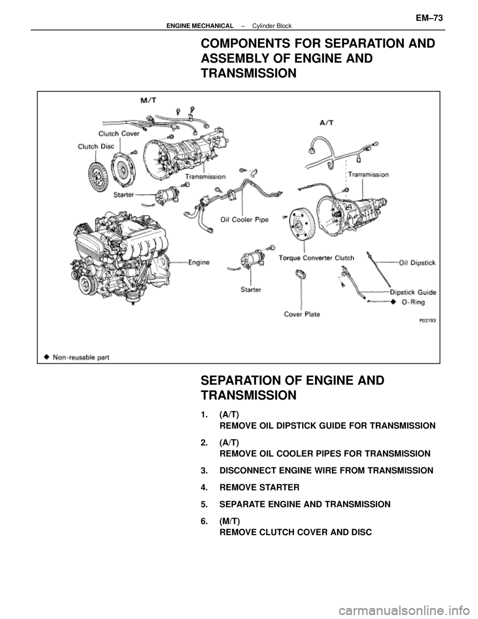
COMPONENTS FOR SEPARATION AND
ASSEMBLY OF ENGINE AND
TRANSMISSION
SEPARATION OF ENGINE AND
TRANSMISSION
1. (A/T)REMOVE OIL DIPSTICK GUIDE FOR TRANSMISSION
2. (A/T) REMOVE OIL COOLER PIPES FOR TRANSMISSION
3. DISCONNECT ENGINE WIRE FROM TRANSMISSION
4. REMOVE STARTER
5. SEPARATE ENGINE AND TRANSMISSION
6. (M/T) REMOVE CLUTCH COVER AND DISC
±
ENGINE MECHANICAL Cylinder BlockEM±73
WhereEverybodyKnowsYourName
Page 1829 of 4087
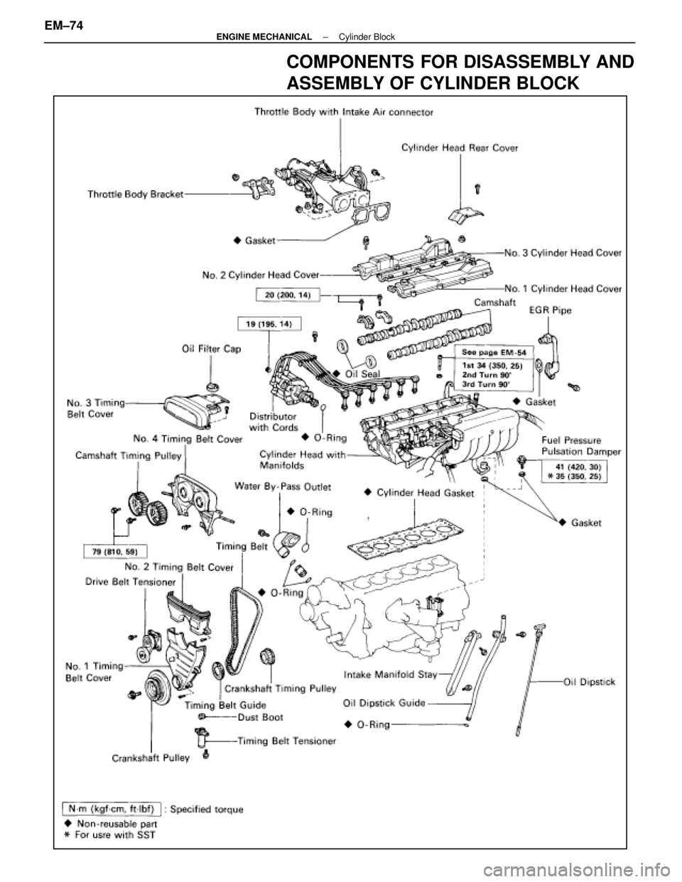
COMPONENTS FOR DISASSEMBLY AND
ASSEMBLY OF CYLINDER BLOCK
EM±74±
ENGINE MECHANICAL Cylinder Block
WhereEverybodyKnowsYourName
Page 1830 of 4087
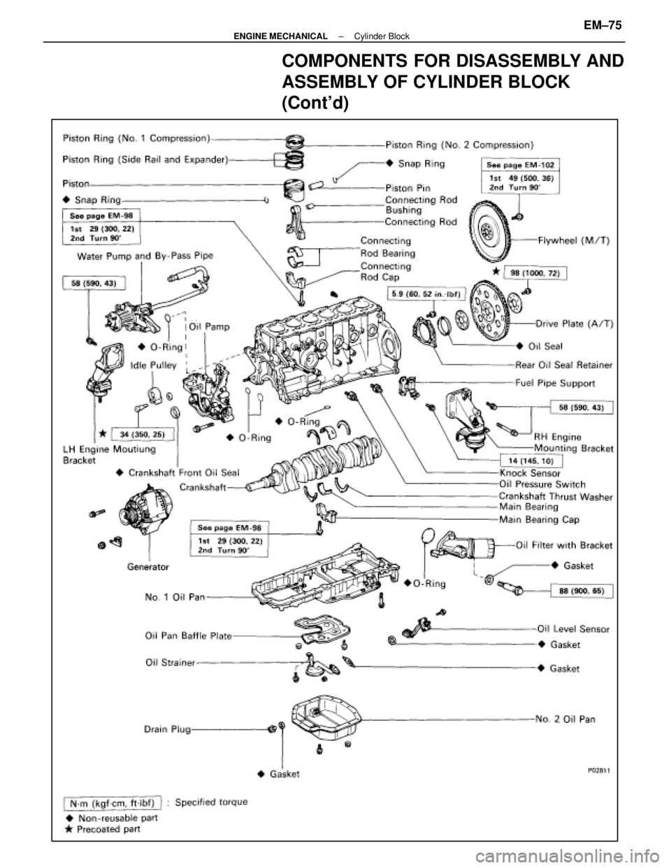
COMPONENTS FOR DISASSEMBLY AND
ASSEMBLY OF CYLINDER BLOCK
(Cont'd)
±
ENGINE MECHANICAL Cylinder BlockEM±75
WhereEverybodyKnowsYourName
Trending: CD changer, washer fluid, inflation pressure, wiring diagram, ignition, heating, check engine light


